EP1227559A1 - Anordnung einer elektrischen Anschlussvorrichtung für eine Einbauleuchte - Google Patents
Anordnung einer elektrischen Anschlussvorrichtung für eine Einbauleuchte Download PDFInfo
- Publication number
- EP1227559A1 EP1227559A1 EP02075145A EP02075145A EP1227559A1 EP 1227559 A1 EP1227559 A1 EP 1227559A1 EP 02075145 A EP02075145 A EP 02075145A EP 02075145 A EP02075145 A EP 02075145A EP 1227559 A1 EP1227559 A1 EP 1227559A1
- Authority
- EP
- European Patent Office
- Prior art keywords
- cover
- main wall
- arrangement
- support tab
- box
- Prior art date
- Legal status (The legal status is an assumption and is not a legal conclusion. Google has not performed a legal analysis and makes no representation as to the accuracy of the status listed.)
- Granted
Links
- 239000002184 metal Substances 0.000 claims description 9
- 230000000295 complement effect Effects 0.000 claims description 2
- 238000009434 installation Methods 0.000 description 6
- 239000000463 material Substances 0.000 description 4
- 239000011521 glass Substances 0.000 description 3
- 238000003754 machining Methods 0.000 description 2
- 230000001681 protective effect Effects 0.000 description 2
- 238000002788 crimping Methods 0.000 description 1
- 238000009792 diffusion process Methods 0.000 description 1
- 238000000465 moulding Methods 0.000 description 1
- 238000004080 punching Methods 0.000 description 1
- 230000000717 retained effect Effects 0.000 description 1
Images






Classifications
-
- H—ELECTRICITY
- H02—GENERATION; CONVERSION OR DISTRIBUTION OF ELECTRIC POWER
- H02G—INSTALLATION OF ELECTRIC CABLES OR LINES, OR OF COMBINED OPTICAL AND ELECTRIC CABLES OR LINES
- H02G3/00—Installations of electric cables or lines or protective tubing therefor in or on buildings, equivalent structures or vehicles
- H02G3/02—Details
- H02G3/08—Distribution boxes; Connection or junction boxes
- H02G3/18—Distribution boxes; Connection or junction boxes providing line outlets
- H02G3/20—Ceiling roses or other lighting sets
Definitions
- the present invention relates to the arrangement of a electrical connection device for a luminaire.
- the present invention relates more particularly the arrangement of an electrical connection device of a luminaire, of the type in which the luminaire comprises a box recessed, especially in a ceiling, which has a wall main plane substantially, an electrical connector being fixed on the internal face of the main wall, in order to allow the electrical connection of the luminaire to the supply network.
- fluorescent type lighting tubes are mounted inside the box, then they are covered with a grille, or glass, protection and diffusion.
- An electric power cable is passed through a light from the main wall of the box, then it is connected electrically to the electrical connector, or internal terminal block.
- the luminaire When installing the luminaire in a ceiling, as the electrical connector is fixed on the inside of the wall main box, it is necessary to open the luminaire, i.e. to dismantle the grid, or the glass, and the tubes, so the installer can access the connector and there connect the power cable.
- a box containing a connector electric is fixed on the internal face of the main wall of the box, facing a window made in this wall.
- the housing has a cover that extends outside of the box, through the window, and which has two lights for the passage of two electric cables.
- the installer When the installer wishes to connect the luminaire to the electrical network, it connects the power cable to the electrical connector from outside the box, then it close the cover.
- This arrangement does not allow to choose between a internal connection and an external connection.
- Some luminaires require replacing the connector of the three-pin type by a connector of the five-pin type, in to allow its connection to two electric wires additional. This is particularly the case when the luminaire has a double ignition function, i.e. it has several groups of light tubes which can operate independently, or when it includes a device to vary the intensity of the lighting (“dimming"), or when it includes an emergency lighting function, i.e. that it is equipped with a battery that allows it to operate in the event of a power failure.
- a double ignition function i.e. it has several groups of light tubes which can operate independently, or when it includes a device to vary the intensity of the lighting (“dimming"), or when it includes an emergency lighting function, i.e. that it is equipped with a battery that allows it to operate in the event of a power failure.
- the mounting of the connector inside a housing is also penalizing for the installer, because he has only a few space to make the electrical connection of the cable the connector.
- this arrangement requires an electric wire additional, which connects the connector to the luminaire housing, in order to make the electrical connection of the connector to earth.
- the invention aims to remedy these drawbacks by proposing an arrangement of an electrical connection device which is easier to install and which allows both internal connection and an external connection, as well as one more great modularity in the choice of connector.
- the arrangement according to the invention allows the installation of the luminaire and its connection to the electrical network by a single no one, without having to open the luminaire.
- the invention therefore makes it possible to deliver luminaires in which the protection tubes and the grid, or the glass, are already mounted, which saves installation time not negligible.
- the arrangement according to the invention makes it possible to mount a connector of the type with three pins or of the type with five studs, without the need to change the size of the cover or the size of the support leg.
- the connector is easily accessible, from the inside and outside of the box, since it is not mounted inside a housing, which facilitates connection electric and makes the installation of the luminaire safer.
- FIG. 1 shows a light box 10 and the various elements of the arrangement 12 of the electrical connection according to the invention.
- the box 10 is advantageously made of sheet metal and it has overall a parallelepiped shape, its side walls 14 being substantially vertical.
- the casing 10 is open at its lower part and is closed at its upper part by an upper main wall horizontal 16 forming the bottom of the box 10.
- the wall main 16 has a cutout 18 which delimits a opening, or window 20, and a tab 22 substantially rectangular support for an electrical connector 24.
- the support tab 22 is therefore here made of a single part by cutting with the main wall 16.
- An attached plate constitutes a cover 26 which is designed to fit into window 20.
- the window 20 is here substantially rectangular and it is preferably made along an upper edge 28 of the box 10.
- the window 20 and the support tab 22 may belong to an insert 30 which is fixed on the main wall 16 of the box 10, above an opening 31 practiced in the main wall 16.
- the insert 30 can be made of sheet metal like the box 10, or in another material such as a material plastic.
- the front-to-back orientation broadly corresponds to orientation from left to right, considering Figure 1.
- the support tab 22 is made of a single piece with main wall 16.
- the support tab 22 is shown here in the position of rest, that is to say, it is substantially contained in the plane of the main wall 16.
- the support tab 22 In its rest position, the support tab 22 extends backwards from the front edge 32 of the cutout 18.
- the underside 34 of the support tab 22 is provided to carry the electrical connector 24.
- it comprises here holes 36 allowing for example the fixing of the connector 24 by screwing, or by hot crimping of pins belonging to the plastic insulating body of the connector 24.
- the support tab 22 is capable of pivot, towards the outside of the box 10, here upwards, around an axis of articulation B-B which is orthogonal to the longitudinal axis A-A and which is contained globally in the plane of the wall main 16.
- the axis of articulation B-B is here substantially coincides with the front edge 32 of the cutout 18.
- connection area 38 of the tab support 22 with the main wall 16 is deformable, so to form a hinge.
- the support tab 22 includes a slot 40, extending along the axis of articulation B-B, which reduces the rigidity of the connection area 38, in order to facilitate its deformation around the axis of articulation B-B.
- the holes 36 and the slot 40 of the support tab 22 are made for example by machining, or during the operation of cutting and punching of the sheet metal constituting the box.
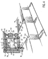
- the ghost lines in Figure 3 represent the leg of support 22 in a raised position substantially vertically, which it occupies when an operator causes it to pivot towards outside, around its axis of articulation B-B.
- the cover 26 is mounted on the tab support 22 by a sliding slide assembly.
- the cover 26 has on its internal face 42 guide legs 44 in L which are aligned along each longitudinal edge 46, 48 of the support tab 22 and which are bent towards the internal face 34 of the support tab 22.
- the cover 26 has two guide tabs 44 on each longitudinal edge 46, 48 of the support tab 22.
- the cover 26 is capable of sliding axially, with respect to the support tab 22, along an axis of sliding C-C which is globally contained in the plane of the cover 26 and which is substantially orthogonal to the axis of joint B-B.
- the cover 26 can slide between a unlocked rear position and locked front position of cover 26, as will be explained later.
- the cover 26 also has a rear edge 50 which is substantially orthogonal to the general plane of the cover 26 and which extends downwards, considering figure 3.
- the mounting of the cover 26 on the support tab 22 is carried out by sliding the cover 26, along the axis of sliding C-C, towards the axis of articulation B-B, the legs of guide 44 being engaged on the longitudinal edges 46, 48 of the support tab 22.
- cover 26 can be mounted on the tab support 22 when the latter occupies its rest position, as in Figure 3, or when it occupies a raised position outward, as in Figure 4.
- the assembly 52 is tilted, that is to say the cover 26 mounted on the support tab 22, towards inside and towards the rear, around the axis of articulation B-B, until the support tab 22 again occupies its rest position, the cover 26 thus acting as a flap hinged closing window 20.
- the underside 42 of the cover 26 carries two lateral locking lugs 54, 55 which are arranged each side of the support tab 22 and which are provided for cooperate with notches 59, 61, made in the part front of the longitudinal edges 56, 57 of the cutout 18, of so as to allow a bayonet type locking of the cover 26 in window 20.
- locking lugs 54, 55 When the cover 26 occupies its locked position and closed in window 20, locking lugs 54, 55 then extend under the longitudinal edges 56, 57 associated with the cutout 18, and they are adjacent to the internal face 58 of the main wall 16. The pins 54, 55 thus prevent the pivoting of the assembly 52 around the axis of articulation B-B, outwards.
- FIG. 7 illustrates the position of one of the lugs 54 of locking when the cover 26 occupies its position locked.
- the cover 26 has here, near its edge before 60, two pins 62, 64.
- the two pins 62, 64 extend longitudinally under the edge front 32 of cutout 18 and they are adjacent to the inner face 58 of the main wall 16, so that they retain the face internal 42 of the cover 26 against the main wall 16.
- the rear edge 50 of the cover 26 is in axial support A-A forwards against the side wall 14 of the box 10.
- the rear edge 50 therefore forms an axial stop, since it prevents the cover 26 from sliding further forward, along the sliding axis A-A.
- the cover 26 here comprises two lights 66, 68, of a side of the support tab 22, which are open in an edge longitudinal 70 of cover 26.
- the lights 66, 68 each allow the passage of a electric cable or wire through the cover 26 in its position locked.
- the two lights 66, 68 are used for example when we carry out a "transplanting", that is to say that we connect electrically another electrical appliance (not shown) at supply network via connector 24 of the box 10.
- each light 66, 68 comprises a substantially circular portion 72, generally of the diameter of the electric cable, and a trapezoidal portion 74 which narrows towards the circular portion 72 and which widens towards the edge longitudinal 70 associated with the cover 26.
- the cover 26 is produced by molding in plastic material.
- the cover can be made by machining and / or in another material.
- the cover 26 has holes oblong 37, oriented in a direction parallel to the axis of sliding C-C, which are made above the holes of fixing 36 of the support tab 22, so as to allow access to the fixing screws (not shown) of the connector 24 on the support tab 22, whatever the axial position (C-C) of the cover 26 relative to the support tab 22.
- the luminaire box 10 is delivered with its lighting tubes and its protective grid (not shown) mounted inside.
- the electrical connector 24 is already connected electrically to the lighting tubes and it is fixed on the face lower 34, or internal, of the support tab 22.
- the cover 26 is mounted on the support tab 22 and it occupies its closed and locked position, so as to avoid risk of damage to the assembly 52 during transport of the box 10 previously equipped.
- the installer therefore arranges box 10 of the luminaire in the ceiling for installation.
- the installer does then slide the cover 26 backwards, along the axis longitudinal A-A, until the lateral pins of lock 54, 55 come out of window 20.
- the cover 26 then occupies its unlocked position which is shown in section in Figure 9.
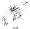
- the installer can then rotate the assembly 52 around the articulation axis B-B outwards, until it occupies a raised position, represented in particular on the Figures 10 and 11, which allows the installer easy access to connector 24 from the outside.
- the installer then connects the wires 76 of the electric cable supply 78 in the pads 80 of the connector 24, in keeping the end of the cable 78 substantially opposite the studs 80.
- the pads 80 are oriented here in a direction generally parallel to the axis of articulation B-B, on the side where the cover 26 has its lights 66, 68, in order to facilitate the electrical connection.
- the connector 24 can also be arranged to classic way, that is to say offset by 90 °, around the axis of sliding C-C, relative to the position which is represented in the present figures, so that the studs 80 are oriented in a direction generally orthogonal to the plane general of the support tab 22, towards the inside of the box 10 when the support tab 22 occupies its rest position.
- the installer holds so the end section of the cable 78 in a direction substantially parallel to the axis of articulation B-B, so that the end of the cable 78 opens out substantially vis-à-vis the studs 80.
- connection 24 is easily accessible since it is not contained in a case and is held in position by the support tab 22 which retains its vertical orientation during the connection maneuver.
- the installer switches the cable 78 forwards, so as to pass its section end in a lumen 68 of the cover 26, such as shown in figure 13.
- connection of the luminaire is then finished and it is ready to operate.
- the arrangement 12 according to the invention makes it possible to make the electrical connection without the need to bend or bend the end section of the electrical cable 78.
- the end section of the cable 78 is only bent in view closing the cover 26, passing the cable 78 through a light 68 of the cover 26.
- the connector 24 is fixed directly on the support leg 22 made of sheet metal, which forms a mass, no additional electrical wire required to electrically connect the connector to ground.
- the plastic cover 26 protects the electric cable 78 from sharp edges sheet metal of the cutout 18.
- the cable 78 is retained in the circular portion 72 of light 68 because light 68 opens towards the associated edge 70 of the cover 26 by a narrowed portion 74, of longitudinal dimension substantially less than cable diameter 78.
- the installer operates from classic way, as with a luminaire with a arrangement made according to the state of the art.
- the installer dismantles the protective grid and the lighting tubes of the housing 10. It then passes the section end of the power supply cable 78 in a light 68 of the cover 26, which remains in its locked position.
Landscapes
- Engineering & Computer Science (AREA)
- Architecture (AREA)
- Civil Engineering (AREA)
- Structural Engineering (AREA)
- Arrangement Of Elements, Cooling, Sealing, Or The Like Of Lighting Devices (AREA)
- Connector Housings Or Holding Contact Members (AREA)
- Fastening Of Light Sources Or Lamp Holders (AREA)
- Non-Portable Lighting Devices Or Systems Thereof (AREA)
Applications Claiming Priority (2)
| Application Number | Priority Date | Filing Date | Title |
|---|---|---|---|
| FR0100888 | 2001-01-23 | ||
| FR0100888A FR2819949A1 (fr) | 2001-01-23 | 2001-01-23 | Agencement d'un dispositif de connexion electrique d'un luminaire encastrable |
Publications (2)
| Publication Number | Publication Date |
|---|---|
| EP1227559A1 true EP1227559A1 (de) | 2002-07-31 |
| EP1227559B1 EP1227559B1 (de) | 2011-07-27 |
Family
ID=8859142
Family Applications (1)
| Application Number | Title | Priority Date | Filing Date |
|---|---|---|---|
| EP02075145A Expired - Lifetime EP1227559B1 (de) | 2001-01-23 | 2002-01-14 | Anordnung einer elektrischen Anschlussvorrichtung für eine Einbauleuchte |
Country Status (4)
| Country | Link |
|---|---|
| EP (1) | EP1227559B1 (de) |
| CN (2) | CN1251378C (de) |
| AT (1) | ATE518287T1 (de) |
| FR (1) | FR2819949A1 (de) |
Cited By (2)
| Publication number | Priority date | Publication date | Assignee | Title |
|---|---|---|---|---|
| EP1564484A3 (de) * | 2004-01-21 | 2010-12-29 | Zumtobel Staff GmbH | Leuchtengehäuse oder Leuchte mit einem Leuchtengehäuse |
| EP3771860A1 (de) * | 2019-08-01 | 2021-02-03 | Ningbo Ganpe Optoelectronics Co., Ltd. | Downlight |
Families Citing this family (1)
| Publication number | Priority date | Publication date | Assignee | Title |
|---|---|---|---|---|
| CN101552440B (zh) * | 2008-03-03 | 2013-04-03 | 威尔摩得公司 | 地板内盒子的上盖组件 |
Citations (3)
| Publication number | Priority date | Publication date | Assignee | Title |
|---|---|---|---|---|
| US4688491A (en) * | 1986-09-08 | 1987-08-25 | Allsteel Inc. | Grommet arrangement for office furniture desk tops |
| US5167047A (en) * | 1991-10-01 | 1992-12-01 | Plumley Roger K | Wire management grommet |
| EP0597765A1 (de) * | 1992-11-10 | 1994-05-18 | Legrand | Einbaudose zur Leuchteaufhängung an einer Decke |
-
2001
- 2001-01-23 FR FR0100888A patent/FR2819949A1/fr not_active Withdrawn
-
2002
- 2002-01-14 AT AT02075145T patent/ATE518287T1/de not_active IP Right Cessation
- 2002-01-14 EP EP02075145A patent/EP1227559B1/de not_active Expired - Lifetime
- 2002-01-19 CN CN02106469.5A patent/CN1251378C/zh not_active Expired - Lifetime
- 2002-01-19 CN CN200510054524.XA patent/CN1661276A/zh active Pending
Patent Citations (3)
| Publication number | Priority date | Publication date | Assignee | Title |
|---|---|---|---|---|
| US4688491A (en) * | 1986-09-08 | 1987-08-25 | Allsteel Inc. | Grommet arrangement for office furniture desk tops |
| US5167047A (en) * | 1991-10-01 | 1992-12-01 | Plumley Roger K | Wire management grommet |
| EP0597765A1 (de) * | 1992-11-10 | 1994-05-18 | Legrand | Einbaudose zur Leuchteaufhängung an einer Decke |
Cited By (2)
| Publication number | Priority date | Publication date | Assignee | Title |
|---|---|---|---|---|
| EP1564484A3 (de) * | 2004-01-21 | 2010-12-29 | Zumtobel Staff GmbH | Leuchtengehäuse oder Leuchte mit einem Leuchtengehäuse |
| EP3771860A1 (de) * | 2019-08-01 | 2021-02-03 | Ningbo Ganpe Optoelectronics Co., Ltd. | Downlight |
Also Published As
| Publication number | Publication date |
|---|---|
| ATE518287T1 (de) | 2011-08-15 |
| CN1370950A (zh) | 2002-09-25 |
| CN1661276A (zh) | 2005-08-31 |
| FR2819949A1 (fr) | 2002-07-26 |
| CN1251378C (zh) | 2006-04-12 |
| EP1227559B1 (de) | 2011-07-27 |
Similar Documents
| Publication | Publication Date | Title |
|---|---|---|
| EP1038731A1 (de) | Dachauskleidung für Kraftfahrzeuge | |
| FR2543744A1 (fr) | Antenne pour auto-radio | |
| EP1227559B1 (de) | Anordnung einer elektrischen Anschlussvorrichtung für eine Einbauleuchte | |
| EP3815972B1 (de) | Träger- und vrebindungsvorrichtung einer elektronischen karte für die steuerung eines licht- oder signalisierungsmoduls eines kraftfahrzeugs | |
| FR2738676A1 (fr) | Appareil electrique a bornes de raccordement protegees par un diaphragme | |
| EP3840151B1 (de) | Schaltkasten und zugehörige elektrische ausrüstung | |
| EP0915537A1 (de) | Elektrische Unterputzvorrichtung mit Befestigungsklemmbacken | |
| EP0677892B1 (de) | Kontakttragender Modul und diesen umfassender Verbinder | |
| EP0547929B1 (de) | Elektrische Anschlussbuchse, insbesondere für Kraftfahrzeuge | |
| EP0911932B1 (de) | Montageadapter für nichtquadratisch geformtes elektrisches Apparat | |
| EP3840152B1 (de) | Gerätehalterung für die montage in eine wand geringer dicke, und gerätemodul, das eine solche hatlerung umfasst | |
| FR2677937A1 (fr) | Structure de fixation d'une piece d'attache pour appareil d'essuyage modulaire. | |
| FR2810467A1 (fr) | Dispositif de montage d'un appareil electrique sur un conduit de cablage | |
| EP0911575B1 (de) | Beleuchtungs- oder Signalvorrichtung mit einem Stecker zum Anschluss an ein Fahrzeug | |
| EP3311065B1 (de) | Sicherheitsbeleuchtungsvorrichtung | |
| FR2751481A1 (fr) | Installation d'alimentation de dispositifs electriques sur des pavillons de vehicules | |
| EP1343236B1 (de) | Vorrichtung zum Montieren von elektrischen Apparaten mit einem Scharnier | |
| EP1251601A1 (de) | Elektromagnetische Abschirmungsvorrichtung für elektrische Verbinder | |
| EP0871252B1 (de) | Verbindungsvorrichtung für die Verbindung von zumindest zwei elektrischen Kabeln | |
| FR2726235A3 (fr) | Feu d'eclairage de vehicule | |
| WO2021122051A1 (fr) | Appareillage electrique | |
| FR3119567A1 (fr) | Dispositif de fixation de la platine de support des connecteurs de batterie de vehicules automobiles | |
| FR2754217A1 (fr) | Bras de support coude en deux parties pour pare-soleil | |
| FR2842032A1 (fr) | Entretoise et boitier comportant cette entretoise | |
| FR3105614A1 (fr) | Boîte électrique et appareillage électrique associé |
Legal Events
| Date | Code | Title | Description |
|---|---|---|---|
| PUAI | Public reference made under article 153(3) epc to a published international application that has entered the european phase |
Free format text: ORIGINAL CODE: 0009012 |
|
| AK | Designated contracting states |
Kind code of ref document: A1 Designated state(s): AT BE CH CY DE DK ES FI FR GB GR IE IT LI LU MC NL PT SE TR |
|
| AX | Request for extension of the european patent |
Free format text: AL;LT;LV;MK;RO;SI |
|
| 17P | Request for examination filed |
Effective date: 20030131 |
|
| AKX | Designation fees paid |
Designated state(s): AT BE CH CY DE DK ES FI FR GB GR IE IT LI LU MC NL PT SE TR |
|
| GRAP | Despatch of communication of intention to grant a patent |
Free format text: ORIGINAL CODE: EPIDOSNIGR1 |
|
| GRAS | Grant fee paid |
Free format text: ORIGINAL CODE: EPIDOSNIGR3 |
|
| GRAA | (expected) grant |
Free format text: ORIGINAL CODE: 0009210 |
|
| AK | Designated contracting states |
Kind code of ref document: B1 Designated state(s): AT BE CH CY DE DK ES FI FR GB GR IE IT LI LU MC NL PT SE TR |
|
| REG | Reference to a national code |
Ref country code: GB Ref legal event code: FG4D Free format text: NOT ENGLISH |
|
| REG | Reference to a national code |
Ref country code: CH Ref legal event code: EP |
|
| REG | Reference to a national code |
Ref country code: DE Ref legal event code: R096 Ref document number: 60240594 Country of ref document: DE Effective date: 20110915 |
|
| REG | Reference to a national code |
Ref country code: NL Ref legal event code: VDEP Effective date: 20110727 |
|
| REG | Reference to a national code |
Ref country code: AT Ref legal event code: MK05 Ref document number: 518287 Country of ref document: AT Kind code of ref document: T Effective date: 20110727 |
|
| PG25 | Lapsed in a contracting state [announced via postgrant information from national office to epo] |
Ref country code: SE Free format text: LAPSE BECAUSE OF FAILURE TO SUBMIT A TRANSLATION OF THE DESCRIPTION OR TO PAY THE FEE WITHIN THE PRESCRIBED TIME-LIMIT Effective date: 20110727 Ref country code: FI Free format text: LAPSE BECAUSE OF FAILURE TO SUBMIT A TRANSLATION OF THE DESCRIPTION OR TO PAY THE FEE WITHIN THE PRESCRIBED TIME-LIMIT Effective date: 20110727 Ref country code: NL Free format text: LAPSE BECAUSE OF FAILURE TO SUBMIT A TRANSLATION OF THE DESCRIPTION OR TO PAY THE FEE WITHIN THE PRESCRIBED TIME-LIMIT Effective date: 20110727 Ref country code: PT Free format text: LAPSE BECAUSE OF FAILURE TO SUBMIT A TRANSLATION OF THE DESCRIPTION OR TO PAY THE FEE WITHIN THE PRESCRIBED TIME-LIMIT Effective date: 20111128 |
|
| PG25 | Lapsed in a contracting state [announced via postgrant information from national office to epo] |
Ref country code: CY Free format text: LAPSE BECAUSE OF FAILURE TO SUBMIT A TRANSLATION OF THE DESCRIPTION OR TO PAY THE FEE WITHIN THE PRESCRIBED TIME-LIMIT Effective date: 20110727 Ref country code: AT Free format text: LAPSE BECAUSE OF FAILURE TO SUBMIT A TRANSLATION OF THE DESCRIPTION OR TO PAY THE FEE WITHIN THE PRESCRIBED TIME-LIMIT Effective date: 20110727 Ref country code: GR Free format text: LAPSE BECAUSE OF FAILURE TO SUBMIT A TRANSLATION OF THE DESCRIPTION OR TO PAY THE FEE WITHIN THE PRESCRIBED TIME-LIMIT Effective date: 20111028 |
|
| REG | Reference to a national code |
Ref country code: IE Ref legal event code: FD4D |
|
| PG25 | Lapsed in a contracting state [announced via postgrant information from national office to epo] |
Ref country code: IE Free format text: LAPSE BECAUSE OF FAILURE TO SUBMIT A TRANSLATION OF THE DESCRIPTION OR TO PAY THE FEE WITHIN THE PRESCRIBED TIME-LIMIT Effective date: 20110727 |
|
| PLBE | No opposition filed within time limit |
Free format text: ORIGINAL CODE: 0009261 |
|
| STAA | Information on the status of an ep patent application or granted ep patent |
Free format text: STATUS: NO OPPOSITION FILED WITHIN TIME LIMIT |
|
| PG25 | Lapsed in a contracting state [announced via postgrant information from national office to epo] |
Ref country code: DK Free format text: LAPSE BECAUSE OF FAILURE TO SUBMIT A TRANSLATION OF THE DESCRIPTION OR TO PAY THE FEE WITHIN THE PRESCRIBED TIME-LIMIT Effective date: 20110727 |
|
| 26N | No opposition filed |
Effective date: 20120502 |
|
| BERE | Be: lapsed |
Owner name: KONINKLIJKE PHILIPS ELECTRONICS N.V. Effective date: 20120131 |
|
| REG | Reference to a national code |
Ref country code: DE Ref legal event code: R097 Ref document number: 60240594 Country of ref document: DE Effective date: 20120502 |
|
| PG25 | Lapsed in a contracting state [announced via postgrant information from national office to epo] |
Ref country code: MC Free format text: LAPSE BECAUSE OF NON-PAYMENT OF DUE FEES Effective date: 20120131 |
|
| REG | Reference to a national code |
Ref country code: CH Ref legal event code: PL |
|
| PG25 | Lapsed in a contracting state [announced via postgrant information from national office to epo] |
Ref country code: LI Free format text: LAPSE BECAUSE OF NON-PAYMENT OF DUE FEES Effective date: 20120131 Ref country code: CH Free format text: LAPSE BECAUSE OF NON-PAYMENT OF DUE FEES Effective date: 20120131 |
|
| PG25 | Lapsed in a contracting state [announced via postgrant information from national office to epo] |
Ref country code: BE Free format text: LAPSE BECAUSE OF NON-PAYMENT OF DUE FEES Effective date: 20120131 |
|
| PG25 | Lapsed in a contracting state [announced via postgrant information from national office to epo] |
Ref country code: ES Free format text: LAPSE BECAUSE OF FAILURE TO SUBMIT A TRANSLATION OF THE DESCRIPTION OR TO PAY THE FEE WITHIN THE PRESCRIBED TIME-LIMIT Effective date: 20111107 |
|
| REG | Reference to a national code |
Ref country code: DE Ref legal event code: R082 Ref document number: 60240594 Country of ref document: DE Representative=s name: VOLMER, GEORG, DIPL.-ING., DE |
|
| PG25 | Lapsed in a contracting state [announced via postgrant information from national office to epo] |
Ref country code: TR Free format text: LAPSE BECAUSE OF FAILURE TO SUBMIT A TRANSLATION OF THE DESCRIPTION OR TO PAY THE FEE WITHIN THE PRESCRIBED TIME-LIMIT Effective date: 20110727 |
|
| REG | Reference to a national code |
Ref country code: DE Ref legal event code: R082 Ref document number: 60240594 Country of ref document: DE Representative=s name: VOLMER, GEORG, DIPL.-ING., DE Effective date: 20140328 Ref country code: DE Ref legal event code: R081 Ref document number: 60240594 Country of ref document: DE Owner name: KONINKLIJKE PHILIPS N.V., NL Free format text: FORMER OWNER: KONINKLIJKE PHILIPS ELECTRONICS N.V., EINDHOVEN, NL Effective date: 20110725 Ref country code: DE Ref legal event code: R081 Ref document number: 60240594 Country of ref document: DE Owner name: KONINKLIJKE PHILIPS N.V., NL Free format text: FORMER OWNER: KONINKLIJKE PHILIPS ELECTRONICS N.V., EINDHOVEN, NL Effective date: 20140328 Ref country code: DE Ref legal event code: R082 Ref document number: 60240594 Country of ref document: DE Representative=s name: MEISSNER, BOLTE & PARTNER GBR, DE Effective date: 20140328 Ref country code: DE Ref legal event code: R082 Ref document number: 60240594 Country of ref document: DE Representative=s name: MEISSNER BOLTE PATENTANWAELTE RECHTSANWAELTE P, DE Effective date: 20140328 Ref country code: DE Ref legal event code: R081 Ref document number: 60240594 Country of ref document: DE Owner name: PHILIPS LIGHTING HOLDING B.V., NL Free format text: FORMER OWNER: KONINKLIJKE PHILIPS ELECTRONICS N.V., EINDHOVEN, NL Effective date: 20140328 Ref country code: DE Ref legal event code: R081 Ref document number: 60240594 Country of ref document: DE Owner name: PHILIPS LIGHTING HOLDING B.V., NL Free format text: FORMER OWNER: KONINKLIJKE PHILIPS ELECTRONICS N.V., EINDHOVEN, NL Effective date: 20110725 |
|
| PG25 | Lapsed in a contracting state [announced via postgrant information from national office to epo] |
Ref country code: LU Free format text: LAPSE BECAUSE OF NON-PAYMENT OF DUE FEES Effective date: 20120114 |
|
| REG | Reference to a national code |
Ref country code: FR Ref legal event code: CA Effective date: 20141126 Ref country code: FR Ref legal event code: CD Owner name: KONINKLIJKE PHILIPS ELECTRONICS N.V., NL Effective date: 20141126 |
|
| REG | Reference to a national code |
Ref country code: FR Ref legal event code: PLFP Year of fee payment: 15 |
|
| REG | Reference to a national code |
Ref country code: DE Ref legal event code: R082 Ref document number: 60240594 Country of ref document: DE Representative=s name: MEISSNER, BOLTE & PARTNER GBR, DE Ref country code: DE Ref legal event code: R082 Ref document number: 60240594 Country of ref document: DE Representative=s name: MEISSNER BOLTE PATENTANWAELTE RECHTSANWAELTE P, DE |
|
| REG | Reference to a national code |
Ref country code: GB Ref legal event code: 732E Free format text: REGISTERED BETWEEN 20161006 AND 20161012 |
|
| REG | Reference to a national code |
Ref country code: FR Ref legal event code: PLFP Year of fee payment: 16 |
|
| REG | Reference to a national code |
Ref country code: DE Ref legal event code: R081 Ref document number: 60240594 Country of ref document: DE Owner name: SIGNIFY HOLDING B.V., NL Free format text: FORMER OWNER: KONINKLIJKE PHILIPS N.V., EINDHOVEN, NL Ref country code: DE Ref legal event code: R082 Ref document number: 60240594 Country of ref document: DE Representative=s name: MEISSNER BOLTE PATENTANWAELTE RECHTSANWAELTE P, DE Ref country code: DE Ref legal event code: R081 Ref document number: 60240594 Country of ref document: DE Owner name: PHILIPS LIGHTING HOLDING B.V., NL Free format text: FORMER OWNER: KONINKLIJKE PHILIPS N.V., EINDHOVEN, NL |
|
| REG | Reference to a national code |
Ref country code: FR Ref legal event code: PLFP Year of fee payment: 17 |
|
| REG | Reference to a national code |
Ref country code: DE Ref legal event code: R082 Ref document number: 60240594 Country of ref document: DE Representative=s name: MEISSNER BOLTE PATENTANWAELTE RECHTSANWAELTE P, DE Ref country code: DE Ref legal event code: R081 Ref document number: 60240594 Country of ref document: DE Owner name: SIGNIFY HOLDING B.V., NL Free format text: FORMER OWNER: PHILIPS LIGHTING HOLDING B.V., EINDHOVEN, NL |
|
| PGFP | Annual fee paid to national office [announced via postgrant information from national office to epo] |
Ref country code: FR Payment date: 20210127 Year of fee payment: 20 |
|
| PGFP | Annual fee paid to national office [announced via postgrant information from national office to epo] |
Ref country code: GB Payment date: 20210128 Year of fee payment: 20 Ref country code: DE Payment date: 20210129 Year of fee payment: 20 |
|
| PGFP | Annual fee paid to national office [announced via postgrant information from national office to epo] |
Ref country code: IT Payment date: 20210121 Year of fee payment: 20 |
|
| REG | Reference to a national code |
Ref country code: DE Ref legal event code: R071 Ref document number: 60240594 Country of ref document: DE |
|
| REG | Reference to a national code |
Ref country code: GB Ref legal event code: PE20 Expiry date: 20220113 |
|
| PG25 | Lapsed in a contracting state [announced via postgrant information from national office to epo] |
Ref country code: GB Free format text: LAPSE BECAUSE OF EXPIRATION OF PROTECTION Effective date: 20220113 |