EP1227573A2 - Optimierte Regelung für den Klappensteller einer Fahrzeugklimaanlage - Google Patents
Optimierte Regelung für den Klappensteller einer Fahrzeugklimaanlage Download PDFInfo
- Publication number
- EP1227573A2 EP1227573A2 EP02001321A EP02001321A EP1227573A2 EP 1227573 A2 EP1227573 A2 EP 1227573A2 EP 02001321 A EP02001321 A EP 02001321A EP 02001321 A EP02001321 A EP 02001321A EP 1227573 A2 EP1227573 A2 EP 1227573A2
- Authority
- EP
- European Patent Office
- Prior art keywords
- frequency
- motor
- torque
- shutter
- response
- Prior art date
- Legal status (The legal status is an assumption and is not a legal conclusion. Google has not performed a legal analysis and makes no representation as to the accuracy of the status listed.)
- Granted
Links
Images

Classifications
-
- H—ELECTRICITY
- H02—GENERATION; CONVERSION OR DISTRIBUTION OF ELECTRIC POWER
- H02P—CONTROL OR REGULATION OF ELECTRIC MOTORS, ELECTRIC GENERATORS OR DYNAMO-ELECTRIC CONVERTERS; CONTROLLING TRANSFORMERS, REACTORS OR CHOKE COILS
- H02P8/00—Arrangements for controlling dynamo-electric motors rotating step by step
- H02P8/14—Arrangements for controlling speed or speed and torque
Definitions
- the invention relates to distribution flap actuators or air mixing or recirculation (air intake) in the installations motor vehicle air conditioning.
- the shutters are moved by geared motors in response to actuation orders produced by a central control unit according to the needs to be satisfied such as ventilation start or stop, room temperature adjustment, demisting, defrosting, ...
- the motors of the geared motors generally stepper motors are chosen to deliver the power needed to drive the flaps at maximum speed in all circumstances, i.e. whatever the fluctuations in the supply voltage and the couple needs. Couples needs are variable not only depending on the technology of the shutters and the nature of their drive kinematics, but also depending on conditions instantaneous such as ventilation power, exerted back pressure on the shutter and opposing the desired movement, temperature, ...
- the gearmotors used in the installations of known air conditioning systems are then oversized in power to satisfy the couple's needs.
- the invention aims to allow the use of lower power gearmotors than those used usual today, in order to lower the costs of the installation of air conditioning, but while satisfying the couple's needs and without significantly penalize the speed of execution of orders actuating.
- the adaptation of the control frequency can be carried out by continuously collecting information representing the need for torque delivered by the motor to move the flap, decreasing, if necessary the frequency of piloting in response to an increase torque requirement detected, and when the control frequency is lower than a predetermined maximum frequency, by increasing, the if applicable, the frequency of piloting in response to a decrease detected the need for a couple.
- the variation of the control frequency can be carried out from almost continuously according to the fluctuations in the torque requirement detected, or in stages, the passage from one level to another being controlled in response to the crossing of a threshold by the torque requirement detected.
- the process according to the invention optimizes the use of the available power.
- An oversizing of the power as it would be necessary for satisfying peaks in torque requirements during transitional periods during the shutter displacement phase, becomes unnecessary. These periods possible transients rarely represent more than 20% of the time total actuation of the flaps, so that the engine slows down during these possible transitional periods does not significantly affect the total duration of the actuation.
- the actuation time remaining reduced it is possible without risk of overheating from operating the stepper motor overpowered, by applying a supply voltage corresponding to an overpowered operating mode. As safety, we can then order the engine to stop if a temperature heating limit is exceeded.
- the detection of the torque requirement delivered by the engine can be carried out by measuring a quantity directly or indirectly representative of the torque such as voltage measurement on a phase of the motor, measuring current in a motor winding or measuring instantaneous engine rotation speed, deceleration below of a certain limit reflecting in the latter case the crossing of a torque value threshold for the control frequency used.
- the invention also aims to provide an actuator allowing the implementation of the process defined above.
- the invention also relates to an air conditioning installation vehicle comprising at least one actuator.
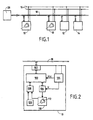
- a automotive air conditioning system includes conventionally a plurality of actuators 10 (of which only two are shown in the figure) to control the movement of air distribution and mixing in order to achieve desired functions of ventilation, cabin temperature adjustment, demisting, defrosting, ... controlled from a control panel 12.
- the actuators 10 as well as the control panel 12 and temperature probes 14 are connected to an energy bus 16 carrying the vehicle battery voltage or a voltage derived from this, and an information link 18.
- the link 18 is advantageously constituted by an information bus.
- Bus 18 is connected to a central control unit 20. This receives status information from control panel 12, probes 14 and actuators 10, such as flap position information and transmits order information, including orders actuating flaps by addressing the actuators 10, these having each a specific address.
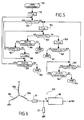
- each actuator 10 comprises a microprocessor-based control unit 100 connected to the information bus 18 by a bus interface 102.
- An electrical supply circuit 104 connected to the energy bus 16 comprises filtering, protection and voltage regulation circuits for supplying a logic supply voltage V cc to the control unit 100 and a motor supply voltage V to an analog interface circuit 106.
- a gearmotor 110 coupled to a air distribution or mixing shutter (not shown) comprises a stepping motor 112 which receives from the circuit 106 the voltage V in the form of pulse trains applied to the phases of the motor at a determined pilot frequency, under the control of the unit 100 to which the interface 106 is connected.
- a data interface 108 is connected to the gearmotor 110 and to the control unit 100 in order to transmit to the latter state data, in particular shutter position data, for example indicating the arrival of the shutter at the end of its travel. .
- the actuator 10 further comprises a circuit 120 providing information representative of the need for torque delivered by the stepping motor 112, for moving the shutter, and the control unit 100 is programmed so as to modify possibly the driving frequency of the motor 112, and therefore the speed of it, according to the information provided by the circuit 120 and received by the control unit for example through the data interface 108.
- circuit 120 Detailed embodiments of a circuit 120 will be described later with reference to Figures 4 and 6.
- the control frequency is adapted during the duration actuation of the shutter to adjust the torque as required.
- AT a given control frequency corresponds to a blocking torque.
- locking torque here we mean the maximum torque that may be required of the motor to move the shutter. If the need for a couple becomes more important, the reduction in the frequency of piloting by the unit 100 allows increase the locking torque. If then the need for a couple decreases, the control frequency can be increased by the unit 100, with corresponding reduction in the locking torque.
- Management of the 112 motor control frequency by the control unit 100 is produced for example as follows (FIG. 3).
- the starting of the motor 112 is controlled at a pilot frequency f equal to the nominal frequency f max , which is the maximum pilot frequency of the engine (phase 132).
- the frequency f max is chosen to initially drive the motor in rotation at a maximum speed preferably corresponding to an overpower regime.
- overpower regime is meant here a mode of operation at a power higher than the nominal power of the engine, which is made possible by the reduced duration of operation during a shutter activation phase and makes it possible to optimize the use of available power.
- test 133 When it is detected, on the basis of the information received from the circuit 120 that the torque requirement delivered by the motor 112 increases beyond a predetermined threshold s 1 (test 133), it is examined whether the shutter has reached in the final position (test 134). If so, the engine is stopped (step 135); otherwise, the driving frequency is decreased by an increment ⁇ f to go to the value f- ⁇ f (step 136).
- test 137 When, after switching to the value f- ⁇ f, a decrease in the torque requirement is detected below a predetermined threshold s 2 (test 137), the control frequency is increased by the value ⁇ f (step 138); otherwise, we return to test 133.
- step 138 When after switching to the value f + ⁇ f (step 138), the value f max is reached (test 139), we return to test 133; otherwise, we return to test 137.
- test 133 does not indicate crossing of the threshold s 1 , we remain at the frequency f max and we loop back to the test 133, if the shutter has not arrived in the final position (test 140), causing the stop of the engine (step 141).
- the arrival of the flap in the final position can be recognized by the control unit 100 in response to receiving information status (for example arriving at the stop) corresponding to this position final.
- the process in FIG. 3 makes it possible to adapt the driving frequency to the torque requirement almost continuously, by choosing for the increment ⁇ f a relatively small value.
- ⁇ f a relatively small value.
- a safety device can be provided to stop the engine (step 143) if an increase in the torque requirement is detected by test 133 while the piloting frequency is at a minimum value f min (test 142).
- FIG. 4 schematically illustrates an embodiment a torque requirement detection circuit 120, of a type known per se, can be used for the implementation of the process of Figure 3.
- the voltage v b at the terminals of a coil 30 of the motor 112 is compared by a comparator 31 to a reference voltage v ref fixed by a diode 32.
- the reference voltage is fixed at a value greater than the voltage normally present at the terminals of the coil 30 when the motor delivers the nominal torque corresponding to the frequency at which it is controlled.
- the comparator 31 When the voltage v b exceeds v ref , reflecting an increase in the torque requirement, the comparator 31 triggers a time counting by a counter 33.
- the value counted by the counter 33 constitutes the information transmitted to the control unit 100 via interface 108.
- the threshold s 1 is fixed at a time value reflecting the persistence of the increase in the torque requirement.
- the counter 33 can be reset to zero by the control unit 100 via the interface 106.
- the threshold s 2 is fixed at a time value less than s 1 .
- FIG. 5 illustrates another embodiment of the motor control frequency management, the management being carried out not continuously but in stages, the control frequency being able for example to take three values: maximum f max , intermediate f int and minimum f min .
- maximum f max 1,200 Hz
- f int 900 Hz
- f min 600 Hz.
- the information transmitted by the circuit 120 is here representative of the value of the instantaneous torque.
- phase 151 In response to an actuation command received (phase 151), the engine is started at frequency f max (phase 152).
- test 153 If the instantaneous torque exceeds a first threshold cp 1 (test 153), the control frequency f is reduced to pass to the intermediate value f int (step 154); otherwise, it is detected if the engine has reached the final position (test 155) to, if so, stop the engine (step 156) or, if not, return to test 153.
- test 162 If the threshold cp 3 is not exceeded, it is detected if the instantaneous torque becomes less than a threshold cp ' 2 (test 162). If so, the control frequency is increased to go to the intermediate value f int (phase 154); otherwise, it is investigated whether the shutter is in the final position (test 164) in order, if so, to stop the motor (step 165) and, if not, to return to test 162.
- test 157 indicates that the threshold cp 2 is not exceeded, it is sought whether the shutter is in the final position (test 166) for, if so, stopping the engine (step 169) and, if not, detecting whether the torque becomes less than a threshold cp ' 1 (test 167). If this is the case, the control frequency is increased to go to the frequency f max (phase 168); otherwise, we return to test 157.
- FIG. 6 schematically illustrates an embodiment a torque requirement detection circuit 120, of a type known per se, can be used for the implementation of the process of Figure 3.
- a voltage v f representative of the current flowing through a coil 30 a , 30 b or 30 c of the motor 112 is taken at the midpoint of a voltage divider formed by two resistors 36, 37 in series with a coil, in this case the coil 30 a .
- the voltage v f is digitized by an A / D converter circuit 38 and transmitted to the control unit 100 via the interface 108.
- the voltage v f represents the electromotive force produced during the rotation of the motor.
- the voltage v f decreases. It is therefore inversely proportional to the torque delivered by the engine.
- the values cp 1 , cp 2 , cp 3 are chosen as a function of the locking torques for the frequencies f max , f int , f min , more precisely a little less than these locking torques .
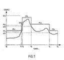
- Figure 7 shows a curve which represents the variation of torque delivered by a stepping motor when a shutter is actuated air inlet. There is a momentary increase in the need for couple.
- the torque thresholds cp 1 , cp 2 , cp 3 are shown as well as the blocking couples cb 1 , cb 2 , cb 3 corresponding to the frequencies f max , f int and f min .
- the torque thresholds cp ' 1 and cp' 2 are also shown. To avoid instability, values for cp ' 1 and cp' 2 will be slightly lower than those of cp 1 and cp 2 , respectively.
- the shutter is driven at maximum speed corresponding to f max between times t 0 (start-up) and t 1 (crossing of cp 1 ) and times t 4 (crossing of cp ' 1 ) and t 5 (arrival of the shutter in final position ).
- t 0 start-up
- t 1 crossing of cp 1
- times t 4 crossing of cp ' 1
- t 5 arrival of the shutter in final position
- the flap is driven at intermediate speed corresponding to f int .
- the flap is driven at minimum speed corresponding to f min .
Landscapes
- Engineering & Computer Science (AREA)
- Power Engineering (AREA)
- Control Of Stepping Motors (AREA)
- Air-Conditioning For Vehicles (AREA)
- Electrically Driven Valve-Operating Means (AREA)
- Cooling, Air Intake And Gas Exhaust, And Fuel Tank Arrangements In Propulsion Units (AREA)
- Control Of Vehicle Engines Or Engines For Specific Uses (AREA)
Applications Claiming Priority (2)
| Application Number | Priority Date | Filing Date | Title |
|---|---|---|---|
| FR0100988A FR2819952B1 (fr) | 2001-01-25 | 2001-01-25 | Commande optimisee d'actionneur de volet d'une installation de climatisation de vehicule automobile |
| FR0100988 | 2001-01-25 |
Publications (3)
| Publication Number | Publication Date |
|---|---|
| EP1227573A2 true EP1227573A2 (de) | 2002-07-31 |
| EP1227573A3 EP1227573A3 (de) | 2002-08-28 |
| EP1227573B1 EP1227573B1 (de) | 2011-04-20 |
Family
ID=8859222
Family Applications (1)
| Application Number | Title | Priority Date | Filing Date |
|---|---|---|---|
| EP02001321A Expired - Lifetime EP1227573B1 (de) | 2001-01-25 | 2002-01-18 | Optimierte Regelung für den Klappensteller einer Fahrzeugklimaanlage |
Country Status (7)
| Country | Link |
|---|---|
| US (1) | US6710570B2 (de) |
| EP (1) | EP1227573B1 (de) |
| JP (1) | JP2002234333A (de) |
| AT (1) | ATE506740T1 (de) |
| DE (1) | DE60239772D1 (de) |
| ES (1) | ES2362995T3 (de) |
| FR (1) | FR2819952B1 (de) |
Cited By (1)
| Publication number | Priority date | Publication date | Assignee | Title |
|---|---|---|---|---|
| FR3066055A1 (fr) * | 2017-05-04 | 2018-11-09 | Valeo Systemes Thermiques | Dispositif de commande d'un moteur pas-a-pas destine a actionner un organe mobile aeraulique dans un vehicule. |
Families Citing this family (5)
| Publication number | Priority date | Publication date | Assignee | Title |
|---|---|---|---|---|
| US7525266B2 (en) * | 2006-01-30 | 2009-04-28 | Honeywell International Inc. | Inverter loop latch with integrated AC detection reset |
| JP2011069336A (ja) * | 2009-09-28 | 2011-04-07 | Keihin Corp | 内燃機関の制御装置 |
| JP2012121516A (ja) * | 2010-12-10 | 2012-06-28 | Aisin Seiki Co Ltd | グリルシャッター開閉制御装置 |
| DE102012103464A1 (de) * | 2012-04-19 | 2013-10-24 | Brose Fahrzeugteile Gmbh & Co. Kommanditgesellschaft, Hallstadt | Stellantrieb einer Luftdurchlassvorrichtung und Verfahren zur Steuerung eines Stellantriebs |
| DE102017205790A1 (de) * | 2017-04-05 | 2018-10-11 | Röchling Automotive SE & Co. KG | Luftklappenvorrichtung mit sanfter Endstellungseinfahrt |
Family Cites Families (13)
| Publication number | Priority date | Publication date | Assignee | Title |
|---|---|---|---|---|
| JPS55103097A (en) * | 1979-01-29 | 1980-08-06 | Hitachi Ltd | System for driving motor for moving stage |
| JPS5928896A (ja) * | 1982-08-05 | 1984-02-15 | Canon Inc | ステツピング・モ−タ制御方式 |
| US4684866A (en) * | 1986-04-16 | 1987-08-04 | General Motors Corporation | Adaptive controller for a motor vehicle engine throttle operator |
| CH670343A5 (de) * | 1986-08-20 | 1989-05-31 | Saia Ag | |
| US5107194A (en) * | 1989-08-14 | 1992-04-21 | Xerox Corporation | Stepper motor control to vary output torque |
| JPH07174041A (ja) * | 1992-07-27 | 1995-07-11 | Honda Motor Co Ltd | 内燃機関の燃料供給制御装置 |
| EP0654892A1 (de) * | 1993-11-19 | 1995-05-24 | Saia Ag | Verfahren zur Schrittmotorsteuerung |
| JP3251782B2 (ja) * | 1994-08-09 | 2002-01-28 | 三菱電機株式会社 | 内燃機関の制御装置 |
| US6016044A (en) * | 1995-09-11 | 2000-01-18 | Alaris Medical Systems, Inc. | Open-loop step motor control system |
| DE19539753B4 (de) * | 1995-10-26 | 2005-12-22 | Kiekert Ag | Kraftfahrzeugtürverschluß mit Zentralverriegelungseinrichtung |
| JPH10248295A (ja) * | 1997-03-03 | 1998-09-14 | Zexel Corp | アクチュエータ制御装置 |
| JP2001136790A (ja) * | 1999-11-08 | 2001-05-18 | Canon Inc | ステッピングモータの駆動制御方法及び装置 |
| US6414455B1 (en) * | 2000-04-03 | 2002-07-02 | Alvin J. Watson | System and method for variable drive pump control |
-
2001
- 2001-01-25 FR FR0100988A patent/FR2819952B1/fr not_active Expired - Lifetime
-
2002
- 2002-01-18 ES ES02001321T patent/ES2362995T3/es not_active Expired - Lifetime
- 2002-01-18 AT AT02001321T patent/ATE506740T1/de not_active IP Right Cessation
- 2002-01-18 EP EP02001321A patent/EP1227573B1/de not_active Expired - Lifetime
- 2002-01-18 DE DE60239772T patent/DE60239772D1/de not_active Expired - Lifetime
- 2002-01-23 US US10/052,517 patent/US6710570B2/en not_active Expired - Lifetime
- 2002-01-25 JP JP2002016667A patent/JP2002234333A/ja active Pending
Cited By (1)
| Publication number | Priority date | Publication date | Assignee | Title |
|---|---|---|---|---|
| FR3066055A1 (fr) * | 2017-05-04 | 2018-11-09 | Valeo Systemes Thermiques | Dispositif de commande d'un moteur pas-a-pas destine a actionner un organe mobile aeraulique dans un vehicule. |
Also Published As
| Publication number | Publication date |
|---|---|
| EP1227573B1 (de) | 2011-04-20 |
| EP1227573A3 (de) | 2002-08-28 |
| FR2819952A1 (fr) | 2002-07-26 |
| US20020097017A1 (en) | 2002-07-25 |
| ES2362995T3 (es) | 2011-07-18 |
| JP2002234333A (ja) | 2002-08-20 |
| FR2819952B1 (fr) | 2003-04-25 |
| ATE506740T1 (de) | 2011-05-15 |
| DE60239772D1 (de) | 2011-06-01 |
| US6710570B2 (en) | 2004-03-23 |
Similar Documents
| Publication | Publication Date | Title |
|---|---|---|
| EP3246194B1 (de) | Klimatisierungssystem für ein elektrisches transportfahrzeug | |
| US4631467A (en) | Escalator passenger flow control | |
| EP1240417B1 (de) | Verfahren und vorrichtung zur leistungsregelung einer hubschrauber-rotor-antriebseinheit | |
| EP3696084B1 (de) | Optimierungsverfahren des von einem drehflügelflugzeug am boden erzeugten lärms | |
| FR2986573A1 (fr) | Procede automatique de regulation d'un groupe de motorisation d'aeronef, dispositif et aeronef | |
| EP2293429A2 (de) | Gesicherte Vorrichtung zur Überwachung und Steuerung für ein Flugzeugsteuerung-stellglied | |
| EP2906440B1 (de) | Method of electric energy recuperation with voltage smoothing of an on-board supply system | |
| EP1227573B1 (de) | Optimierte Regelung für den Klappensteller einer Fahrzeugklimaanlage | |
| FR2769043A1 (fr) | Dispositif de demarrage a courant alternatif d'un groupe turbo-moteur d'helicoptere | |
| EP3718841B1 (de) | Bremssystem eines luftfahrzeugrads, das gemäss normal-modus oder rto-modus eingestellt werden kann | |
| FR3012399A1 (fr) | Systeme de charge de vehicule | |
| EP0658972B1 (de) | System zur Steuerung der Versorgung eines Asynchronmotors | |
| FR2965128A1 (fr) | Procede et dispositif de gestion d'un generateur d'un systeme de recuperation d'energie d'un vehicule automobile | |
| EP0982825B1 (de) | Drehzahlregelvorrichtung für einen elektrischen Motor und Vorrichtung zum Schleudern mit einer solchen Vorrichtung | |
| EP0402220B1 (de) | Verfahren und Vorrichtung zur Regelung eines Schrittmotors | |
| EP1772953B1 (de) | Verfahren zur Aufrechterhaltung der Gleichstromspannung am Eingang eines Gleichtrom-Wechselstrom Konverters, Speichermedium für das Verfahren und elektrisches Fahrzeug | |
| FR3066055B1 (fr) | Dispositif de commande d'un moteur pas-a-pas destine a actionner un organe mobile aeraulique dans un vehicule. | |
| FR2503482A1 (fr) | Procede et systeme de circuit d'alimentation d'une machine electrique asynchrone utilisee comme moteur de commande d'entrainement | |
| EP1109688B1 (de) | Vorrichtung für die heizung, lüftung und/oder klimatisierung mit wenigstens einem beweglichem organ, das von einem unipolarmotor kontrollirt wird | |
| FR3062973B1 (fr) | Alterno-demarreur, vehicule automobile et procede de commande associes | |
| EP4183993B1 (de) | Verfahren zur verwaltung von leistungsmengen, die auf leistungseinheiten der antriebsanordnungen eines flugzeugs entnommen wurden | |
| EP4559807A1 (de) | Überwachungssystem zur überwachung einer hybriden antriebsanlage eines drehflüglers, entsprechendes drehflügelflugzeug und verfahren | |
| WO2024246102A1 (fr) | Procédé de commande d'un alternateur de véhicule automobile. | |
| FR2836300A1 (fr) | Ligne de controle de mise en veille pour un bus de climatisation de vehicule automobile | |
| FR2668662A1 (fr) | Procede de protection d'un moteur electrique contre les surcharges. |
Legal Events
| Date | Code | Title | Description |
|---|---|---|---|
| PUAI | Public reference made under article 153(3) epc to a published international application that has entered the european phase |
Free format text: ORIGINAL CODE: 0009012 |
|
| PUAL | Search report despatched |
Free format text: ORIGINAL CODE: 0009013 |
|
| AK | Designated contracting states |
Kind code of ref document: A2 Designated state(s): AT BE CH CY DE DK ES FI FR GB GR IE IT LI LU MC NL PT SE TR |
|
| AX | Request for extension of the european patent |
Free format text: AL;LT;LV;MK;RO;SI |
|
| AK | Designated contracting states |
Kind code of ref document: A3 Designated state(s): AT BE CH CY DE DK ES FI FR GB GR IE IT LI LU MC NL PT SE TR |
|
| AX | Request for extension of the european patent |
Free format text: AL;LT;LV;MK;RO;SI |
|
| 17P | Request for examination filed |
Effective date: 20030210 |
|
| AKX | Designation fees paid |
Designated state(s): AT BE CH CY DE DK ES FI FR GB GR IE IT LI LU MC NL PT SE TR |
|
| 17Q | First examination report despatched |
Effective date: 20100218 |
|
| GRAP | Despatch of communication of intention to grant a patent |
Free format text: ORIGINAL CODE: EPIDOSNIGR1 |
|
| GRAS | Grant fee paid |
Free format text: ORIGINAL CODE: EPIDOSNIGR3 |
|
| GRAA | (expected) grant |
Free format text: ORIGINAL CODE: 0009210 |
|
| RAP1 | Party data changed (applicant data changed or rights of an application transferred) |
Owner name: VALEO SYSTEMES THERMIQUES |
|
| AK | Designated contracting states |
Kind code of ref document: B1 Designated state(s): AT BE CH CY DE DK ES FI FR GB GR IE IT LI LU MC NL PT SE TR |
|
| REG | Reference to a national code |
Ref country code: GB Ref legal event code: FG4D Free format text: NOT ENGLISH |
|
| REG | Reference to a national code |
Ref country code: CH Ref legal event code: EP |
|
| REG | Reference to a national code |
Ref country code: CH Ref legal event code: NV Representative=s name: CRONIN INTELLECTUAL PROPERTY |
|
| REG | Reference to a national code |
Ref country code: IE Ref legal event code: FG4D Free format text: LANGUAGE OF EP DOCUMENT: FRENCH |
|
| REF | Corresponds to: |
Ref document number: 60239772 Country of ref document: DE Date of ref document: 20110601 Kind code of ref document: P |
|
| REG | Reference to a national code |
Ref country code: DE Ref legal event code: R096 Ref document number: 60239772 Country of ref document: DE Effective date: 20110601 |
|
| REG | Reference to a national code |
Ref country code: SE Ref legal event code: TRGR |
|
| REG | Reference to a national code |
Ref country code: ES Ref legal event code: FG2A Ref document number: 2362995 Country of ref document: ES Kind code of ref document: T3 Effective date: 20110718 |
|
| REG | Reference to a national code |
Ref country code: NL Ref legal event code: VDEP Effective date: 20110420 |
|
| PG25 | Lapsed in a contracting state [announced via postgrant information from national office to epo] |
Ref country code: PT Free format text: LAPSE BECAUSE OF FAILURE TO SUBMIT A TRANSLATION OF THE DESCRIPTION OR TO PAY THE FEE WITHIN THE PRESCRIBED TIME-LIMIT Effective date: 20110822 |
|
| REG | Reference to a national code |
Ref country code: IE Ref legal event code: FD4D |
|
| PG25 | Lapsed in a contracting state [announced via postgrant information from national office to epo] |
Ref country code: FI Free format text: LAPSE BECAUSE OF FAILURE TO SUBMIT A TRANSLATION OF THE DESCRIPTION OR TO PAY THE FEE WITHIN THE PRESCRIBED TIME-LIMIT Effective date: 20110420 Ref country code: CY Free format text: LAPSE BECAUSE OF FAILURE TO SUBMIT A TRANSLATION OF THE DESCRIPTION OR TO PAY THE FEE WITHIN THE PRESCRIBED TIME-LIMIT Effective date: 20110420 Ref country code: AT Free format text: LAPSE BECAUSE OF FAILURE TO SUBMIT A TRANSLATION OF THE DESCRIPTION OR TO PAY THE FEE WITHIN THE PRESCRIBED TIME-LIMIT Effective date: 20110420 Ref country code: GR Free format text: LAPSE BECAUSE OF FAILURE TO SUBMIT A TRANSLATION OF THE DESCRIPTION OR TO PAY THE FEE WITHIN THE PRESCRIBED TIME-LIMIT Effective date: 20110721 |
|
| PG25 | Lapsed in a contracting state [announced via postgrant information from national office to epo] |
Ref country code: NL Free format text: LAPSE BECAUSE OF FAILURE TO SUBMIT A TRANSLATION OF THE DESCRIPTION OR TO PAY THE FEE WITHIN THE PRESCRIBED TIME-LIMIT Effective date: 20110420 |
|
| PG25 | Lapsed in a contracting state [announced via postgrant information from national office to epo] |
Ref country code: IE Free format text: LAPSE BECAUSE OF FAILURE TO SUBMIT A TRANSLATION OF THE DESCRIPTION OR TO PAY THE FEE WITHIN THE PRESCRIBED TIME-LIMIT Effective date: 20110420 |
|
| PLBE | No opposition filed within time limit |
Free format text: ORIGINAL CODE: 0009261 |
|
| STAA | Information on the status of an ep patent application or granted ep patent |
Free format text: STATUS: NO OPPOSITION FILED WITHIN TIME LIMIT |
|
| PG25 | Lapsed in a contracting state [announced via postgrant information from national office to epo] |
Ref country code: DK Free format text: LAPSE BECAUSE OF FAILURE TO SUBMIT A TRANSLATION OF THE DESCRIPTION OR TO PAY THE FEE WITHIN THE PRESCRIBED TIME-LIMIT Effective date: 20110420 |
|
| 26N | No opposition filed |
Effective date: 20120123 |
|
| REG | Reference to a national code |
Ref country code: DE Ref legal event code: R097 Ref document number: 60239772 Country of ref document: DE Effective date: 20120123 |
|
| BERE | Be: lapsed |
Owner name: VALEO SYSTEMES THERMIQUES Effective date: 20120131 |
|
| PG25 | Lapsed in a contracting state [announced via postgrant information from national office to epo] |
Ref country code: MC Free format text: LAPSE BECAUSE OF NON-PAYMENT OF DUE FEES Effective date: 20120131 |
|
| PG25 | Lapsed in a contracting state [announced via postgrant information from national office to epo] |
Ref country code: BE Free format text: LAPSE BECAUSE OF NON-PAYMENT OF DUE FEES Effective date: 20120131 |
|
| PG25 | Lapsed in a contracting state [announced via postgrant information from national office to epo] |
Ref country code: TR Free format text: LAPSE BECAUSE OF FAILURE TO SUBMIT A TRANSLATION OF THE DESCRIPTION OR TO PAY THE FEE WITHIN THE PRESCRIBED TIME-LIMIT Effective date: 20110420 |
|
| PG25 | Lapsed in a contracting state [announced via postgrant information from national office to epo] |
Ref country code: LU Free format text: LAPSE BECAUSE OF NON-PAYMENT OF DUE FEES Effective date: 20120118 |
|
| REG | Reference to a national code |
Ref country code: FR Ref legal event code: PLFP Year of fee payment: 15 |
|
| REG | Reference to a national code |
Ref country code: FR Ref legal event code: PLFP Year of fee payment: 16 |
|
| REG | Reference to a national code |
Ref country code: FR Ref legal event code: PLFP Year of fee payment: 17 |
|
| REG | Reference to a national code |
Ref country code: CH Ref legal event code: PCAR Free format text: NEW ADDRESS: CHEMIN DE LA VUARPILLIERE 29, 1260 NYON (CH) |
|
| PGFP | Annual fee paid to national office [announced via postgrant information from national office to epo] |
Ref country code: FR Payment date: 20210128 Year of fee payment: 20 Ref country code: CH Payment date: 20210122 Year of fee payment: 20 |
|
| PGFP | Annual fee paid to national office [announced via postgrant information from national office to epo] |
Ref country code: DE Payment date: 20210112 Year of fee payment: 20 Ref country code: SE Payment date: 20210120 Year of fee payment: 20 Ref country code: ES Payment date: 20210208 Year of fee payment: 20 Ref country code: GB Payment date: 20210118 Year of fee payment: 20 |
|
| PGFP | Annual fee paid to national office [announced via postgrant information from national office to epo] |
Ref country code: IT Payment date: 20210118 Year of fee payment: 20 |
|
| REG | Reference to a national code |
Ref country code: DE Ref legal event code: R071 Ref document number: 60239772 Country of ref document: DE |
|
| REG | Reference to a national code |
Ref country code: CH Ref legal event code: PL |
|
| REG | Reference to a national code |
Ref country code: GB Ref legal event code: PE20 Expiry date: 20220117 |
|
| REG | Reference to a national code |
Ref country code: ES Ref legal event code: FD2A Effective date: 20220426 |
|
| PG25 | Lapsed in a contracting state [announced via postgrant information from national office to epo] |
Ref country code: GB Free format text: LAPSE BECAUSE OF EXPIRATION OF PROTECTION Effective date: 20220117 |
|
| PG25 | Lapsed in a contracting state [announced via postgrant information from national office to epo] |
Ref country code: ES Free format text: LAPSE BECAUSE OF EXPIRATION OF PROTECTION Effective date: 20220119 |
|
| P01 | Opt-out of the competence of the unified patent court (upc) registered |
Effective date: 20230528 |