EP1228526B1 - Vorrichtung zum bestücken von teileträgern für mikrosysteme - Google Patents
Vorrichtung zum bestücken von teileträgern für mikrosysteme Download PDFInfo
- Publication number
- EP1228526B1 EP1228526B1 EP00977520A EP00977520A EP1228526B1 EP 1228526 B1 EP1228526 B1 EP 1228526B1 EP 00977520 A EP00977520 A EP 00977520A EP 00977520 A EP00977520 A EP 00977520A EP 1228526 B1 EP1228526 B1 EP 1228526B1
- Authority
- EP
- European Patent Office
- Prior art keywords
- gripper
- rotation
- axis
- unit
- working
- Prior art date
- Legal status (The legal status is an assumption and is not a legal conclusion. Google has not performed a legal analysis and makes no representation as to the accuracy of the status listed.)
- Expired - Lifetime
Links
Images


Classifications
-
- H—ELECTRICITY
- H10—SEMICONDUCTOR DEVICES; ELECTRIC SOLID-STATE DEVICES NOT OTHERWISE PROVIDED FOR
- H10P—GENERIC PROCESSES OR APPARATUS FOR THE MANUFACTURE OR TREATMENT OF DEVICES COVERED BY CLASS H10
- H10P72/00—Handling or holding of wafers, substrates or devices during manufacture or treatment thereof
- H10P72/04—Apparatus for manufacture or treatment
- H10P72/0446—Apparatus for mounting on conductive members, e.g. leadframes or conductors on insulating substrates
-
- H—ELECTRICITY
- H10—SEMICONDUCTOR DEVICES; ELECTRIC SOLID-STATE DEVICES NOT OTHERWISE PROVIDED FOR
- H10P—GENERIC PROCESSES OR APPARATUS FOR THE MANUFACTURE OR TREATMENT OF DEVICES COVERED BY CLASS H10
- H10P72/00—Handling or holding of wafers, substrates or devices during manufacture or treatment thereof
- H10P72/04—Apparatus for manufacture or treatment
- H10P72/0442—Apparatus for placing on an insulating substrate, e.g. tape
Definitions
- DE 196 54 231 A1 describes a handling unit for components known, the one in an atmospheric chamber Has workstation in the components on a ring zone of a Turntable are arranged, which feeds from a loading station becomes.
- the chamber also contains a measuring station as well a rotating arm unit, the arms of which rotate a sector of the Paint over the ring zone of the turntable covered with components and include height-adjustable suction pads over which the components picked up by the turntable, transferred to the measuring station and from the measuring station into the overlap area to an outside the rotating arm unit lying in the working chamber which forms a withdrawal stage and from which the Components are transferred to an unloading station.
- the measuring station is offset in height from an intermediate store forming turntable and to the turntable forming the removal stage and a curve is provided through which the Suction cup on its way from the turntable to the measuring station and led from the measuring station to the removal stage in the height direction become.
- This guide device is as both upward as also limited downward constrained guidance designed to one unwanted height offset of the suction cups on their path and to exclude damage caused by this.
- the handling unit is designed as Carousel with various protruding radially to the carousel axis Support arms that carry substrate grippers, which during the circulation of the Carousels transport the substrates between each Stations, which in turn are partly independent of the carousel and rotary tables designed eccentrically to the carousel axis or carousels are trained.
- the carousel arms are positioned opposite each other also at least one carousel arm, which in turn is relative to the other carousel arms in relation to the common carousel axis is pivotable to increase work flexibility.
- the loading of the work islands the planetary table is carried out via a rotatable gripper unit, which is laterally offset from the planetary table and radial has claw areas projecting to its axis of rotation, which in the from the work islands with rotation of the planet table intervene overlapped ring zone.
- the invention has for its object one for assembly and / or Sorting to create suitable device with which is simple, space-saving, high adjustment speeds enabling access to the work islands over their entire area when aligned to varying Component contours can be achieved, especially as a process module for built in cluster construction and / or in clean room technology operated work centers is to be used.
- a device of the type mentioned is used for this purpose Designed according to the characterizing part of claim 1, being the rotation of the planet carrier in conjunction with the rotation of the planets as working islands in relation to the planet carrier allows within the rotation of the planet carrier ring area described by the working islands mutual rotation of planet carrier and work islands against each other through each point on a circular line to place the axes of rotation of the work islands, their center coincides with the axis of rotation of the planet carrier, so that when the planet carrier and the gripper unit by rotating the gripper unit around its device-fixed axis of rotation additionally an alignment on the Contour of components to be detected is possible, at only rotating mobility of planet carriers, Work islands and gripping unit.
- the revolver adjustable in height namely adjustable in height in particular in the direction of the axis of rotation of the gripper unit.
- the height adjustment of the axially displaceable relative to the outer part is advantageously carried out via a Adjusting eccentric, which is in a radially open annular groove of the inner part intervenes when its drive is supported against the housing the gripper unit.
- This also carries the drive motors for the revolving turret or the rotation of the carrying unit by Rotary axis of the gripper unit, so that there are simple drive connections result.
- the axis of rotation 7 of the planet carrier 6 is fixed in space and the order Rotation axes 8 with respect to the planet carrier 6 rotatable, planet of the planet carrier 6 forming work islands 5 when the planet carrier 6 rotates an annular zone to which one Gripper unit 9 lies in overlap, the housing 10 of which is fixed to the frame is arranged and which has an axis of rotation 11, which parallel to the axes of rotation 8 of the planets 5 and on the same Cylinder jacket like this.
Landscapes
- Specific Conveyance Elements (AREA)
- Sampling And Sample Adjustment (AREA)
- Manipulator (AREA)
- Ventilation (AREA)
Description
- Fig. 1
- eine perspektivische Gesamtansicht einer erfindungsgemäßen Vorrichtung zum Bestücken von Teileträgern für Mikrosysteme, die insbesondere als Prozessmodul für ein in Clusterbauweise aufgebautes und gegebenenfalls auch in Reinraumtechnik arbeitendes Arbeitszentrum einsetzbar ist,
- Fig. 2
- eine Draufsicht auf die Vorrichtung gemäß Fig. 1, in weiterer Schematisierung,
- Fig. 3
- eine stark schematisierte Schnittdarstellung durch die Vorrichtung gemäß Fig. 1 bei einer Schnittführung gemäß III-III,
- Fig. 4
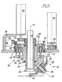
- einen Schnitt durch die Greifereinheit der Vorrichtung in schematisierter, vereinfachter Darstellung, und
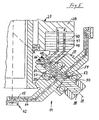
- Fig. 5
- eine vergrößerte Darstellung des den Drehrevolver umfassenden Bereiches der Greifereinheit gemäß Fig. 4, ebenfalls schematisiert und vereinfacht.
Claims (11)
- Vorrichtung zum Bestücken von Teileträgern für Mikrosysteme, insbesondere ein Prozessmodul für in Clusterbauweise aufgebaute Arbeitszentren, umfassend einen um eine zentrale Achse (7) drehbaren Planetenträger (6) mit Planeten als Arbeitsinseln (5), dem eine drehbare Greifereinheit (9) zugeordnet ist, die einen im Überdeckungsbereich zur von den Arbeitsinseln (5) bei Drehung des Planetenträgers (6) bestrichenen Ringfläche liegenden Arbeitspunkt aufweist, der auf einer Kreislinie durch die Drehachsen (8) der Arbeitsinseln (5) liegt, wobei der Mittel-punkt der kreislinie mit der Drehachse (7) des Planetenträgers (6) zusammenfällt,
dadurch gekennzeichnet, dass die Drehachsen (8) der Arbeitsinseln (5) zusammen mit der vorrichtungsfesten Drehachse (11) der Greifereinheit (9) auf einem zur Drehachse (7) des Planetenträgers (6) konzentrischen Zylindermantel liegen. - Vorrichtung nach Anspruch 1,
dadurch gekennzeichnet, dass die Arbeitsinseln (5) voneinander unabhängig höhenverstellbar sind. - Vorrichtung nach Anspruch 1 oder 2,
dadurch gekennzeichnet, dass die Greifereinheit (9) einen Greiferkopf (14) umfasst, der als Drehrevolver mit über seinen Umfang zueinander beabstandeten Greiferfingern (15) ausgebildet ist und dessen Greiferfinger (15) im Durchlauf durch die Drehachse (11) der Greifereinheit (9) diese senkrecht schneiden. - Vorrichtung nach Anspruch 3,
dadurch gekennzeichnet, dass die Drehachse (39) des Greiferkopfes (14) unter einem Winkel von 45° zur Drehachse (11) der Greifereinheit (9) geneigt ist und diese schneidet. - Vorrichtung nach einem der vorhergehenden Ansprüche 3 oder 4,
dadurch gekennzeichnet, dass der Greifereinheit (9) eine auf den Arbeitspunkt des Greiferkopfes (14) ausgerichtete, in der Drehachse (11) der Greifereinheit (9) liegende Beobachtungsoptik (41) zugeordnet ist. - Vorrichtung nach Anspruch 5,
dadurch gekennzeichnet, dass der Greiferkopf (14) von einer zur vorrichtungsfesten Drehachse (11) der Greifereinheit (9) konzentrischen Hohlwelle (24) angetrieben ist, die die Beobachtungsoptik (41) umschließt. - Vorrichtung nach Anspruch 6,
dadurch gekennzeichnet, dass die Hohlwelle (24) in Richtung der Drehachse (11) der Greifereinheit (9) axial verschieblich ist und dass der Greiferkopf (14) über eine zur Hohlwelle (24) konzentrische Trageinheit (16) gehalten ist, die ihrerseits vorrichtungsfest drehbar gelagert ist. - Vorrichtung nach Anspruch 7,
dadurch gekennzeichnet, dass die Trageinheit (16) einen vorrichtungsfesten, drehbar abgestützten äußeren Teil (22) und einen gegenüber diesem axial verstellbaren Innenteil (23) aufweist, der den Greiferkopf (14) und die Lagerung für die Hohlwelle (24) trägt. - Vorrichtung nach Anspruch 7,
dadurch gekennzeichnet, dass die Hohlwelle (24) einen Zahnkranz (36) trägt, dem an dem den Greiferkopf (14) bildenden Drehrevolver ein Gegenkranz (37) zugeordnet ist. - Vorrichtung nach einem der Ansprüche 7 bis 9,
dadurch gekennzeichnet, dass die Hohlwelle (24) mit einem sie tragenden Innenteil (23) in Achsrichtung unverschieblich verbunden ist und dass der Innenteil (23) durch einen vorrichtungsfest abgestützten Exzenter (30) in Achsrichtung verstellbar ist. - Vorrichtung nach einem der Ansprüche 8 bis 10,
dadurch gekennzeichnet, dass der Greiferkopf (14) auf einem gegenüber dem Innenteil (23) feststehenden Achsbolzen (38) gelagert und an seinen Greiferfingern (15) im Bereich des Arbeitspunktes mit Saugstempeln (42) versenen ist, denen durch den Achsbolzen (38) des Greiferkopfes (14) verlaufende Versorgungsleitungen zugeordnet sind.
Applications Claiming Priority (3)
| Application Number | Priority Date | Filing Date | Title |
|---|---|---|---|
| DE19953949A DE19953949A1 (de) | 1999-11-09 | 1999-11-09 | Vorrichtung zum Bestücken von Teileträgern für Mikrosysteme |
| DE19953949 | 1999-11-09 | ||
| PCT/EP2000/011067 WO2001035449A1 (de) | 1999-11-09 | 2000-11-09 | Vorrichtung zum bestücken von teileträgern für mikrosysteme |
Publications (2)
| Publication Number | Publication Date |
|---|---|
| EP1228526A1 EP1228526A1 (de) | 2002-08-07 |
| EP1228526B1 true EP1228526B1 (de) | 2004-02-11 |
Family
ID=7928475
Family Applications (1)
| Application Number | Title | Priority Date | Filing Date |
|---|---|---|---|
| EP00977520A Expired - Lifetime EP1228526B1 (de) | 1999-11-09 | 2000-11-09 | Vorrichtung zum bestücken von teileträgern für mikrosysteme |
Country Status (4)
| Country | Link |
|---|---|
| EP (1) | EP1228526B1 (de) |
| AT (1) | ATE259543T1 (de) |
| DE (2) | DE19953949A1 (de) |
| WO (1) | WO2001035449A1 (de) |
Families Citing this family (2)
| Publication number | Priority date | Publication date | Assignee | Title |
|---|---|---|---|---|
| DE10145819C2 (de) * | 2001-09-17 | 2003-08-14 | Asys Gmbh | Werkzeugbestückung für eine Arbeitseinheit von Mikrosystemen |
| DE10240115B4 (de) * | 2002-08-30 | 2004-10-28 | Advanced Micro Devices, Inc., Sunnyvale | Verfahren und System zum Handhaben von Substraten in einer Produktionslinie mit einer Cluster-Anlage und einer Messanlage |
Family Cites Families (10)
| Publication number | Priority date | Publication date | Assignee | Title |
|---|---|---|---|---|
| US3957185A (en) * | 1975-08-25 | 1976-05-18 | Western Electric Company, Inc. | Methods of and apparatus for thermocompression bonding with a compensating system |
| JPS58158940A (ja) * | 1982-03-16 | 1983-09-21 | Toshiba Corp | Ledペレツト測定装置 |
| US5313401A (en) * | 1989-07-17 | 1994-05-17 | Canon Kabushiki Kaisha | Mounting system including a plurality of hand mechanisms for picking up, moving and mounting works on an object board |
| DE4117969C2 (de) * | 1991-05-31 | 2000-11-09 | Balzers Ag Liechtenstein | Vakuumkammer |
| JPH05267363A (ja) * | 1992-03-24 | 1993-10-15 | Toshiba Corp | ダイボンディング装置 |
| US5330043A (en) * | 1993-05-25 | 1994-07-19 | Delta Design, Inc. | Transfer apparatus and method for testing facility |
| JPH07147300A (ja) * | 1993-11-24 | 1995-06-06 | Hitachi Ltd | インナーリードボンディング装置 |
| TW371347B (en) * | 1995-12-27 | 1999-10-01 | Advantest Corp | Structure of rotary arm and device chuck part of a device handler |
| DE19606764C1 (de) * | 1996-02-23 | 1997-04-03 | Singulus Technologies Gmbh | Vorrichtung zum Greifen, Halten und/oder Transportieren von Substraten |
| JP3601179B2 (ja) * | 1996-04-16 | 2004-12-15 | 松下電器産業株式会社 | 電子部品の組立装置 |
-
1999
- 1999-11-09 DE DE19953949A patent/DE19953949A1/de not_active Withdrawn
-
2000
- 2000-11-09 EP EP00977520A patent/EP1228526B1/de not_active Expired - Lifetime
- 2000-11-09 AT AT00977520T patent/ATE259543T1/de not_active IP Right Cessation
- 2000-11-09 DE DE50005275T patent/DE50005275D1/de not_active Expired - Lifetime
- 2000-11-09 WO PCT/EP2000/011067 patent/WO2001035449A1/de not_active Ceased
Also Published As
| Publication number | Publication date |
|---|---|
| WO2001035449A1 (de) | 2001-05-17 |
| ATE259543T1 (de) | 2004-02-15 |
| DE19953949A1 (de) | 2001-05-17 |
| DE50005275D1 (de) | 2004-03-18 |
| EP1228526A1 (de) | 2002-08-07 |
Similar Documents
| Publication | Publication Date | Title |
|---|---|---|
| EP0312694B1 (de) | Vorrichtung nach dem Karussell-Prinzip zum Beschichten von Substraten | |
| EP0737968B1 (de) | Transportvorrichtung | |
| EP0672595B1 (de) | Vorrichtung für den Transport von Substraten | |
| DE69302586T2 (de) | Halbleiterwafer transport-modul mit drehbarem und horizontal ausziehbarem halter | |
| DE19601433C2 (de) | Mehrstationen-Werkzeugmaschine | |
| DE3935992C2 (de) | Vorrichtung zum Verbinden zweier Glastafeln zu einer am Rand verklebten Isolierglasscheibe | |
| EP0354294A2 (de) | Vorrichtung nach dem Karussell-Prinzip zum Beschichten von Substraten | |
| EP0727345B1 (de) | Anlage zum Zusammenbau von Kraftfahrzeugkarosserien | |
| EP2015981B1 (de) | Vorrichtung zum bearbeiten von bauteilen einer kraftfahrzeugkarosserie | |
| EP1136179A2 (de) | Adaptives Werkstück-Spann- und Handlingssystem | |
| EP2753454B1 (de) | Werkzeugmaschine | |
| DE19744157A1 (de) | Werkzeugmaschinengruppe mit zwei einander gegenüberstehenden Bearbeitungseinheiten | |
| EP0885686A1 (de) | Bearbeitungszelle | |
| EP2753453B1 (de) | Werkzeugmaschine und verfahren zum werkzeugwechsel | |
| EP1228526B1 (de) | Vorrichtung zum bestücken von teileträgern für mikrosysteme | |
| EP1072181B1 (de) | Bestückvorrichtung zum bestücken von bauelementeträgern | |
| DE10222620A1 (de) | Verfahren zum Verarbeiten von elektrischen Bauteilen, insbesondere zum Verarbeiten von Halbleiterchips sowie elektrischen Bauelementen, sowie Vorrichtung zum Durchführen des Verfahrens | |
| EP1214733B1 (de) | Vorrichtung zum be- und entladen von substraten | |
| CH663190A5 (de) | Belade- und entladeeinrichtung fuer werkstuecktraeger. | |
| EP1125869B1 (de) | Montagevorrichtung | |
| WO2021160214A1 (de) | Handhabungsvorrichtung | |
| EP0094338A2 (de) | Roboteranlage | |
| EP1072542B1 (de) | Stapelanlage für Pressen zur Blechformung | |
| EP3932156B1 (de) | Fixiereinrichtung für mobile spulenträger zum aufnehmen von gurtspulen | |
| EP0140837B1 (de) | Bestückungs- und Montageautomat |
Legal Events
| Date | Code | Title | Description |
|---|---|---|---|
| PUAI | Public reference made under article 153(3) epc to a published international application that has entered the european phase |
Free format text: ORIGINAL CODE: 0009012 |
|
| 17P | Request for examination filed |
Effective date: 20020510 |
|
| AK | Designated contracting states |
Kind code of ref document: A1 Designated state(s): AT BE CH CY DE DK ES FI FR GB GR IE IT LI LU MC NL PT SE TR |
|
| 17Q | First examination report despatched |
Effective date: 20030117 |
|
| GRAP | Despatch of communication of intention to grant a patent |
Free format text: ORIGINAL CODE: EPIDOSNIGR1 |
|
| GRAS | Grant fee paid |
Free format text: ORIGINAL CODE: EPIDOSNIGR3 |
|
| GRAA | (expected) grant |
Free format text: ORIGINAL CODE: 0009210 |
|
| AK | Designated contracting states |
Kind code of ref document: B1 Designated state(s): AT BE CH CY DE DK ES FI FR GB GR IE IT LI LU MC NL PT SE TR |
|
| PG25 | Lapsed in a contracting state [announced via postgrant information from national office to epo] |
Ref country code: IT Free format text: LAPSE BECAUSE OF FAILURE TO SUBMIT A TRANSLATION OF THE DESCRIPTION OR TO PAY THE FEE WITHIN THE PRE;WARNING: LAPSES OF ITALIAN PATENTS WITH EFFECTIVE DATE BEFORE 2007 MAY HAVE OCCURRED AT ANY TIME BEFORE 2007. THE CORRECT EFFECTIVE DATE MAY BE DIFFERENT FROM THE ONE RECORDED.SCRIBED TIME-LIMIT Effective date: 20040211 Ref country code: IE Free format text: LAPSE BECAUSE OF FAILURE TO SUBMIT A TRANSLATION OF THE DESCRIPTION OR TO PAY THE FEE WITHIN THE PRESCRIBED TIME-LIMIT Effective date: 20040211 Ref country code: FI Free format text: LAPSE BECAUSE OF FAILURE TO SUBMIT A TRANSLATION OF THE DESCRIPTION OR TO PAY THE FEE WITHIN THE PRESCRIBED TIME-LIMIT Effective date: 20040211 Ref country code: NL Free format text: LAPSE BECAUSE OF FAILURE TO SUBMIT A TRANSLATION OF THE DESCRIPTION OR TO PAY THE FEE WITHIN THE PRESCRIBED TIME-LIMIT Effective date: 20040211 Ref country code: TR Free format text: LAPSE BECAUSE OF FAILURE TO SUBMIT A TRANSLATION OF THE DESCRIPTION OR TO PAY THE FEE WITHIN THE PRESCRIBED TIME-LIMIT Effective date: 20040211 Ref country code: CY Free format text: LAPSE BECAUSE OF FAILURE TO SUBMIT A TRANSLATION OF THE DESCRIPTION OR TO PAY THE FEE WITHIN THE PRESCRIBED TIME-LIMIT Effective date: 20040211 |
|
| REG | Reference to a national code |
Ref country code: GB Ref legal event code: FG4D Free format text: NOT ENGLISH |
|
| REG | Reference to a national code |
Ref country code: CH Ref legal event code: EP |
|
| REG | Reference to a national code |
Ref country code: IE Ref legal event code: FG4D Free format text: GERMAN |
|
| REF | Corresponds to: |
Ref document number: 50005275 Country of ref document: DE Date of ref document: 20040318 Kind code of ref document: P |
|
| GBT | Gb: translation of ep patent filed (gb section 77(6)(a)/1977) |
Effective date: 20040414 |
|
| PG25 | Lapsed in a contracting state [announced via postgrant information from national office to epo] |
Ref country code: GR Free format text: LAPSE BECAUSE OF FAILURE TO SUBMIT A TRANSLATION OF THE DESCRIPTION OR TO PAY THE FEE WITHIN THE PRESCRIBED TIME-LIMIT Effective date: 20040511 Ref country code: SE Free format text: LAPSE BECAUSE OF FAILURE TO SUBMIT A TRANSLATION OF THE DESCRIPTION OR TO PAY THE FEE WITHIN THE PRESCRIBED TIME-LIMIT Effective date: 20040511 Ref country code: DK Free format text: LAPSE BECAUSE OF FAILURE TO SUBMIT A TRANSLATION OF THE DESCRIPTION OR TO PAY THE FEE WITHIN THE PRESCRIBED TIME-LIMIT Effective date: 20040511 |
|
| PG25 | Lapsed in a contracting state [announced via postgrant information from national office to epo] |
Ref country code: ES Free format text: LAPSE BECAUSE OF FAILURE TO SUBMIT A TRANSLATION OF THE DESCRIPTION OR TO PAY THE FEE WITHIN THE PRESCRIBED TIME-LIMIT Effective date: 20040522 |
|
| NLV1 | Nl: lapsed or annulled due to failure to fulfill the requirements of art. 29p and 29m of the patents act | ||
| REG | Reference to a national code |
Ref country code: IE Ref legal event code: FD4D |
|
| ET | Fr: translation filed | ||
| PG25 | Lapsed in a contracting state [announced via postgrant information from national office to epo] |
Ref country code: AT Free format text: LAPSE BECAUSE OF NON-PAYMENT OF DUE FEES Effective date: 20041109 Ref country code: LU Free format text: LAPSE BECAUSE OF NON-PAYMENT OF DUE FEES Effective date: 20041109 |
|
| PG25 | Lapsed in a contracting state [announced via postgrant information from national office to epo] |
Ref country code: CH Free format text: LAPSE BECAUSE OF NON-PAYMENT OF DUE FEES Effective date: 20041130 Ref country code: MC Free format text: LAPSE BECAUSE OF NON-PAYMENT OF DUE FEES Effective date: 20041130 Ref country code: LI Free format text: LAPSE BECAUSE OF NON-PAYMENT OF DUE FEES Effective date: 20041130 Ref country code: BE Free format text: LAPSE BECAUSE OF NON-PAYMENT OF DUE FEES Effective date: 20041130 |
|
| PLBE | No opposition filed within time limit |
Free format text: ORIGINAL CODE: 0009261 |
|
| STAA | Information on the status of an ep patent application or granted ep patent |
Free format text: STATUS: NO OPPOSITION FILED WITHIN TIME LIMIT |
|
| 26N | No opposition filed |
Effective date: 20041112 |
|
| BERE | Be: lapsed |
Owner name: *ASYS G.M.B.H. + CO. K.G. Effective date: 20041130 |
|
| REG | Reference to a national code |
Ref country code: CH Ref legal event code: PL |
|
| BERE | Be: lapsed |
Owner name: *ASYS G.M.B.H. + CO. K.G. Effective date: 20041130 |
|
| PG25 | Lapsed in a contracting state [announced via postgrant information from national office to epo] |
Ref country code: PT Free format text: LAPSE BECAUSE OF NON-PAYMENT OF DUE FEES Effective date: 20040711 |
|
| REG | Reference to a national code |
Ref country code: FR Ref legal event code: PLFP Year of fee payment: 16 |
|
| REG | Reference to a national code |
Ref country code: FR Ref legal event code: PLFP Year of fee payment: 17 |
|
| REG | Reference to a national code |
Ref country code: DE Ref legal event code: R084 Ref document number: 50005275 Country of ref document: DE |
|
| REG | Reference to a national code |
Ref country code: FR Ref legal event code: PLFP Year of fee payment: 18 |
|
| PGFP | Annual fee paid to national office [announced via postgrant information from national office to epo] |
Ref country code: DE Payment date: 20191128 Year of fee payment: 20 |
|
| PGFP | Annual fee paid to national office [announced via postgrant information from national office to epo] |
Ref country code: FR Payment date: 20191124 Year of fee payment: 20 |
|
| PGFP | Annual fee paid to national office [announced via postgrant information from national office to epo] |
Ref country code: GB Payment date: 20191122 Year of fee payment: 20 |
|
| REG | Reference to a national code |
Ref country code: DE Ref legal event code: R071 Ref document number: 50005275 Country of ref document: DE |
|
| REG | Reference to a national code |
Ref country code: GB Ref legal event code: PE20 Expiry date: 20201108 |
|
| PG25 | Lapsed in a contracting state [announced via postgrant information from national office to epo] |
Ref country code: GB Free format text: LAPSE BECAUSE OF EXPIRATION OF PROTECTION Effective date: 20201108 |