EP1228541B1 - Procede de fabrication d'un transducteur piezo-electrique - Google Patents
Procede de fabrication d'un transducteur piezo-electrique Download PDFInfo
- Publication number
- EP1228541B1 EP1228541B1 EP00982998A EP00982998A EP1228541B1 EP 1228541 B1 EP1228541 B1 EP 1228541B1 EP 00982998 A EP00982998 A EP 00982998A EP 00982998 A EP00982998 A EP 00982998A EP 1228541 B1 EP1228541 B1 EP 1228541B1
- Authority
- EP
- European Patent Office
- Prior art keywords
- fibers
- fibres
- piezoelectric
- polymer substance
- fibre segments
- Prior art date
- Legal status (The legal status is an assumption and is not a legal conclusion. Google has not performed a legal analysis and makes no representation as to the accuracy of the status listed.)
- Expired - Lifetime
Links
Images
Classifications
-
- H—ELECTRICITY
- H10—SEMICONDUCTOR DEVICES; ELECTRIC SOLID-STATE DEVICES NOT OTHERWISE PROVIDED FOR
- H10N—ELECTRIC SOLID-STATE DEVICES NOT OTHERWISE PROVIDED FOR
- H10N30/00—Piezoelectric or electrostrictive devices
- H10N30/01—Manufacture or treatment
- H10N30/09—Forming piezoelectric or electrostrictive materials
- H10N30/092—Forming composite materials
-
- Y—GENERAL TAGGING OF NEW TECHNOLOGICAL DEVELOPMENTS; GENERAL TAGGING OF CROSS-SECTIONAL TECHNOLOGIES SPANNING OVER SEVERAL SECTIONS OF THE IPC; TECHNICAL SUBJECTS COVERED BY FORMER USPC CROSS-REFERENCE ART COLLECTIONS [XRACs] AND DIGESTS
- Y10—TECHNICAL SUBJECTS COVERED BY FORMER USPC
- Y10T—TECHNICAL SUBJECTS COVERED BY FORMER US CLASSIFICATION
- Y10T29/00—Metal working
- Y10T29/42—Piezoelectric device making
Definitions
- the invention relates to a method for Production of a piezoelectric transducer, the piezoelectric fibers in a polymer matrix exists on the electrodes for controlling the fibers are applied.
- Piezoelectric materials are important for many technical applications. These are substances that generate electrical charges under the action of mechanical stress or deform under the action of an electric field. The former is known by the term direct piezoelectric effect, the latter being called the indirect piezoelectric effect.
- a certain group of piezoelectric materials represent the piezoceramics. For the production of piezoceramics, the piezoelectric effect must be brought about in a targeted manner by poling the ceramic after sintering in a strong electric field. Here, certain areas of the ceramic, the domains, are aligned along the electric field lines, so that the ceramic is polarized in this direction. After switching off the electric field, a part of this polarization remains as a remanent polarization in the ceramic.
- the currently most commonly used piezoelectric material is lead titanate zirconate (PZT).
- PZT lead titanate zirconate
- This ceramic has been used in the art for a long time in many ways as a resonator, actuator or sensor material. Fine-scale components such as films, rods or fibers are advantageous for many applications. In these, however, there is a problem of low mechanical strength of the piezoelectric ceramics to be provided in this form. This applies both to their handling in the manufacture of complex structures from these ceramics as well as the limited possibility of power transmission through the piezoelectric effect in a component.
- composites consisting of an organic Polymer matrix with incorporated PZT ceramic used.
- the polymer matrix has on the one hand the Task, the thin-walled ceramic elements a to give sufficiently great mechanical stability, and on the other hand, those produced by the piezoceramic Deformations, for example, in the damping of Vibrations to transfer into the structure.
- fiber composites consists in bringing in the long ones piezoelectric fibers in parallel arrangement in the intended form.
- Danger that many fibers break.
- parallel alignment with a significant Associated production costs.
- fibers are often in the production bend slightly and then no longer align parallel to let. This is especially true for very thin fibers with diameters ⁇ 50 microns of the case.
- Fiber composites Another process for the production of Fiber composites is known from DE 198 29 216 A.
- the fibers are over their circumference of the Electrodes contacted directly and at least partially enclosed. This is achieved by placing the fibers in fixed conductive adhesive and then to be shed.
- the adhesive may cure before curing
- This will be the electrical breakdown strength greatly reduced and the likelihood of electrical breakdowns in the polarity of the fibers or at aktorischen applications is very high.
- the object of the present invention is therein, a method of manufacturing a piezoelectric Transducer to specify the above Disadvantages does not have, is easy to carry out and the use of fibers or fiber bundles of any quality allows.
- the procedure should continue also the Production of large non-planar components with allow directly integrated piezoelectric fibers and ensure transducers with high dielectric strength.
- the piezoelectric fibers are wrapped after their preparation either as individual fibers, as a bed of short fiber pieces, as a fiber bundle, ie any grouping of at least two fibers, or in a corresponding combination with a polymer composition.
- This can be done by incorporating the fibers or fiber pieces into a liquid polymer mass or by applying a liquid polymer to the fibers or fiber pieces.
- the piezoelectric fibers or fiber pieces are arranged such that a distribution of the longitudinal axes of the fibers or fiber pieces or - in non-linearly extending fibers - a distribution of the longitudinal axes of sections of the fibers or fiber pieces results in a preferred direction. This is possible without complex precise alignment of the individual components.
- the sheathing of the fibers or fiber pieces is preferably carried out in a designated form, which dictates the outer geometry of the composite.
- the fibers or pieces of fiber are compacted in the polymer, ie brought closer to each other spatially, and the polymer is cured.
- the resulting composite is processed such that along the preferred direction, ie in a plane parallel to the preferred direction, areas of the fibers or pieces of fiber are exposed.
- the electrical contact is applied directly to at least a portion of the exposed areas.
- the individual exposed areas should in this case be so large that at least two opposing electrodes find space in one area.
- a fiber arrangement can be used in which the longitudinal axes of the fibers are randomly distributed around a preferred direction. In the case of the majority of fibers, a maximum deviation of their longitudinal axis from 30 ° from this preferred direction preferably results. In an embodiment in which essentially straight fibers are used, a proportion of at least 50% of the fibers in the polymer matrix deviates from the preferred direction over their length by at least one fiber diameter. It is also possible to use curved fibers which deviate from a rectilinear shape by at least one fiber diameter and therefore can not be aligned in parallel.
- the polymer enveloping the fiber is removed in certain areas in a plane parallel to the preferred direction, then due to the distribution of the longitudinal axes, a certain proportion of the total fibers present can always be contacted.
- the portion which can be contacted in this way comprises both the numerical proportion of the fibers as a whole and the length of the contacted portions of a fiber in the longitudinal direction.
- a fiber does not have to be contacted to its total length, but it is also possible to contact many fibers on short sections of their total length.
- the contacting is preferably carried out by means of an interdigital electrode, which is applied as an electrical contact to the present after processing surface of the composite.
- the electrical contacting can be carried out, for example, by applying an electrically conductive layer on both sides, or by applying an interdigital structure to one or both surfaces.
- the processing of the composite to expose Areas of the fibers can be different Techniques are done. Examples are loops, Laser processing, sawing, sandblasting, wet-chemical Etching or ion beam techniques.
- a particularly advantageous embodiment of the method is to produce a composite with the piezoelectric fibers or fiber pieces according to the inventive method, which has the multiple thickness of the subsequent transducer.
- the preferred direction of the fibers or fiber pieces is perpendicular to the thickness direction of the composite.
- the processing of the composite takes place in this preferred embodiment by separation in planes along the fiber preferred direction. This separation can be done for example by sawing the composite. The separation takes place here in individual plates or discs, which have the thickness of the piezoelectric transducer to be generated. As a result of this sawing, areas of the fibers are exposed on the surface of each of the disks produced thereby and can be contacted by applying electrical contacts.
- the process can be carried out very cost-effectively and simply because several transducers are produced in just a few steps.
- a mold having a dimension of 6 cm x 3 cm is provided.
- This mold is filled with a polymer to be used as a matrix.
- a polymer for example, an epoxy resin can be used.
- 2.5 g of a bundle of piezoelectric fibers having a length of about 5 cm are placed in the liquid polymer in the mold and compacted to form a layer about 0.5 mm thick.
- the individual fibers in this case have a mean fiber diameter of 20 to 30 microns.
- the polymer is cured with the fibers.
- the mold is removed to obtain a flat plate of 6 x 3 x 0.05 cm 3 . This plate is then sanded on the two opposite sides.
- an interdigital electrode of 50 finger pairs with a finger gap of 1 mm is applied from conductive adhesive and subsequently sealed with a thin layer of epoxy resin.
- the second side can be provided in the same way with an interdigital electrode, which is applied congruently with the opposite electrode.
- the resulting piezoelectric transducer in the form of a composite can be used both as a bending reactor, as a strain transducer as well as for sensory purposes. It can also be built into a structure and used for example for the purpose of vibration damping.
- 61 grams of piezoelectric fibers are placed in a liquid epoxy mold and compacted into a 2 x 2 x 5 cm 3 block. After curing, this block is sawed in the fiber longitudinal direction to individual plates of 2 x 5 cm and a thickness of 0.2 mm. Thereafter, an interdigital electrode of 50 finger pairs with a finger spacing of 1 mm is mirror-inverted on each of the plates on both sides and subsequently sealed with a thin layer of epoxy resin.
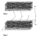
- FIG. 1 shows, by way of example, a block 1 made of resin or polymer-infiltrated fibers 2, produced by compaction and curing, whose longitudinal axes are distributed around a preferred direction 3.
- the non-linear shape of the fibers 2 can be seen very well, which promotes the subsequent contact still.
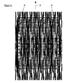
- FIG. 2 indicates a section 4 along which the block 1 is sawn in order to expose regions of the fibers 2 along the preferred direction 3. The surface resulting from the cut along the cut surface 4 is shown in FIG. In this figure, the areas 5 of the fibers 2 exposed by the section along the preferential direction 3 are clearly visible.
- an interdigital electrode 6 is applied for contacting the fibers, the fingers of which extend perpendicular to the preferred direction 3 (see FIG. As a result, a piezoelectric transducer is realized in a simple and cost-effective manner.
Landscapes
- Engineering & Computer Science (AREA)
- Chemical & Material Sciences (AREA)
- Composite Materials (AREA)
- Materials Engineering (AREA)
- Manufacturing & Machinery (AREA)
- Compositions Of Macromolecular Compounds (AREA)
- Transducers For Ultrasonic Waves (AREA)
- Investigating Or Analyzing Materials By The Use Of Ultrasonic Waves (AREA)
- Dc-Dc Converters (AREA)
- Piezo-Electric Transducers For Audible Bands (AREA)
Claims (8)
- Procédé à fabriquer un convertisseur piézoélectrique, comprenant les étapes suivantes :caractérisé en ce que l'enveloppage desdites fibres piézoélectriques (2) ou desdits tronçons de fibres d'une substance polymérique liquide se fait d'une telle manière, que dans la substance polymérique, une orientation en parallèle ne soit pas atteinte, mais une distribution des axes longitudinaux au moins des tronçons de fibres (2) ou segments de fibres autour de ladite direction préférentielle (3), à une agglomération desdites fibres (2) ou tronçons de fibres, l'un relativement à l'autre, avant le durcissement et à un traitement du composite se faisant par séparation dans des plans le long de ladite direction préférentielle (3).envelopper des fibres piézoélectriques (2) ou des tronçons de fibres piézoélectriques d'une substance polymérique liquide ;durcir la substance polymérique, ensemble avec lesdites fibres (2) ou tronçons de fibres, afin de former un composite ;traiter ledit composite d'une telle manière, que des zones (5) desdits fibres (2) ou desdits tronçons de fibres soient exposés le long d'une direction préférentielle (3) ; etdéposer des contacts électriques (6) pour la commande du convertisseur sur au moins une partie desdites zones exposées (5),
- Procédé selon la revendication 1,
caractérisé en ce que ladite séparation se fait par sciage du composite en morceaux en parallèle à ladite direction préférentielle (3). - Procédé selon une quelconque des revendications 1 ou 2,
caractérisé en ce que la séparation se fait moyennant un faisceau laser. - Procédé selon une quelconque des revendications 1 à 3,
caractérisé en ce que lesdits contact électriques (6) sont déposés sous forme d'une ou plusieurs électrodes interdigitales. - Procédé selon une quelconque des revendications 1 à 4,
caractérisé en ce que l'enveloppage se fait par la pose desdites fibres (2) ou desdits tronçons de fibres sous forme d'un faisceau ou en vrac dans une moule et par versement de ladite substance polymérique liquide. - Procédé selon une quelconque des revendications 1 à 5,
caractérisé en ce que ledit composite est fabrique en plaques. - Procédé selon une quelconque des revendications 1 à 6,
dans lequel des fibres (2) ou tronçons de fibres essentiellement droits sont enveloppés par ladite substance polymérique liquide d'une telle façon, qu'au moins 50% des fibres (2) ou tronçons de fibres dans ladite substance polymérique varient de ladite direction préférentielle (3) par au moins un diamètre de fibre sur toute leur longueur. - Procédé selon une quelconque des revendications 1 à 6,
caractérisé en ce que des fibres (2) ou tronçons de fibres sont utilisés, dont au moins la moitié présente une allure courbée qui varie d'une forme rectiligne par au moins un diamètre de fibre.
Applications Claiming Priority (3)
| Application Number | Priority Date | Filing Date | Title |
|---|---|---|---|
| DE19954020 | 1999-11-10 | ||
| DE19954020A DE19954020C2 (de) | 1999-11-10 | 1999-11-10 | Verfahren zur Herstellung eines piezoelektrischen Wandlers |
| PCT/DE2000/003609 WO2001035468A2 (fr) | 1999-11-10 | 2000-10-12 | Procede de fabrication d'un transducteur piezo-electrique |
Publications (2)
| Publication Number | Publication Date |
|---|---|
| EP1228541A2 EP1228541A2 (fr) | 2002-08-07 |
| EP1228541B1 true EP1228541B1 (fr) | 2005-08-17 |
Family
ID=7928524
Family Applications (1)
| Application Number | Title | Priority Date | Filing Date |
|---|---|---|---|
| EP00982998A Expired - Lifetime EP1228541B1 (fr) | 1999-11-10 | 2000-10-12 | Procede de fabrication d'un transducteur piezo-electrique |
Country Status (6)
| Country | Link |
|---|---|
| US (1) | US7228606B1 (fr) |
| EP (1) | EP1228541B1 (fr) |
| JP (1) | JP4896331B2 (fr) |
| AT (1) | ATE302472T1 (fr) |
| DE (2) | DE19954020C2 (fr) |
| WO (1) | WO2001035468A2 (fr) |
Cited By (1)
| Publication number | Priority date | Publication date | Assignee | Title |
|---|---|---|---|---|
| DE102013219550A1 (de) | 2013-09-27 | 2015-04-02 | SCHWEIßTECHNISCHE LEHR- UND VERSUCHSANSTALT HALLE GMBH | Piezokeramische Fasern und diese enthaltender Verbundwerkstoff sowie Ultraschallwandler auf Basis dieses Verbundwerkstoffs |
Families Citing this family (20)
| Publication number | Priority date | Publication date | Assignee | Title |
|---|---|---|---|---|
| DE10135962C1 (de) * | 2001-07-24 | 2003-06-26 | Fraunhofer Ges Forschung | Verfahren zur Herstellung eines kontrolliert deformierbaren Funktionselementes sowie Funktionselement |
| DE10214984B4 (de) | 2002-04-04 | 2006-01-19 | Eads Deutschland Gmbh | Aktorik- und Sensoriksystem für Verbundstrukturen |
| DE10218936B4 (de) * | 2002-04-27 | 2004-03-04 | Neue Materialien Würzburg GmbH | Verfahren zur Herstellung elektromechanischer Wandler |
| RU2320030C2 (ru) | 2002-06-24 | 2008-03-20 | Эл Джи Электроникс Инк. | Носитель записи со структурой данных для управления воспроизведением записанных на нем видеоданных нескольких каналов воспроизведения и способы и устройства записи и воспроизведения |
| DE10329430B4 (de) | 2003-07-01 | 2005-05-04 | Koenig & Bauer Ag | Walze mit integriertem Drucksensor |
| DE102004030205A1 (de) * | 2004-06-22 | 2006-01-19 | Jäger, Frank-Michael | Verfahren und Vorrichtung zur Fehlerkompensation und Überwachung magnetisch-induktiver Durchflussmesser |
| DE202005002216U1 (de) * | 2005-02-11 | 2006-06-22 | Argillon Gmbh | Piezoelektrisches Element |
| DE102005011376A1 (de) * | 2005-03-11 | 2006-09-14 | Siemens Ag | Vorrichtung zur Füllstandsmessung |
| WO2007131227A2 (fr) * | 2006-05-05 | 2007-11-15 | Advanced Cerametrics, Inc. | Dispositif électronique portable autoalimenté |
| DE102008018110B4 (de) | 2007-04-12 | 2022-10-06 | Volkswagen Ag | Nicht sichtbarer Ultraschallsensor |
| DE102009019005A1 (de) * | 2009-04-15 | 2010-11-04 | Taheripur, Mohammad Ali | Vorrichtung zur Umwandlung der Brownschen Bewegungsenergie eines Fluids in elektrische Energie |
| DE102010019666A1 (de) * | 2010-04-28 | 2011-11-03 | Technische Universität Dresden | Aktorisches, sensorisches und/oder generatorisches Faserverbundbauteil und Verfahren zu seiner Herstellung |
| CN102051710B (zh) * | 2010-11-26 | 2012-11-07 | 江苏大学 | 一种微细平直pzt压电纤维阵列的制备方法 |
| DE102011014017B4 (de) * | 2011-03-15 | 2013-06-27 | Lufthansa Technik Ag | Verfahren zur Vorbehandlung eines Faserverbundwerkstoffs |
| DE102011001359A1 (de) | 2011-03-17 | 2012-09-20 | Gottfried Wilhelm Leibniz Universität Hannover | Verfahren und Vorrichtung zur Herstellung einer Piezoaktorenkomponente |
| DE202012104156U1 (de) * | 2012-10-30 | 2013-11-05 | Karlsruher Institut für Technologie Innovationsmanagement | Piezofederelement |
| JP2015109431A (ja) * | 2013-10-23 | 2015-06-11 | 株式会社Kri | 圧電ポリマー膜、アクチュエータ、感圧センサ及びそれを用いたデバイス |
| CN104009670B (zh) * | 2014-06-19 | 2016-06-15 | 厦门大学 | 一种柔性无铅压电钛酸铋钠钾纳米发电装置及其制造方法 |
| CN104638103A (zh) * | 2015-02-04 | 2015-05-20 | 兰州大学 | 一种可发电的透明薄膜及制备方法 |
| CN105047813B (zh) * | 2015-06-17 | 2018-06-29 | 扬州大学 | 一种液体芯压电聚合物器件及其制备方法和应用 |
Family Cites Families (23)
| Publication number | Priority date | Publication date | Assignee | Title |
|---|---|---|---|---|
| US4412148A (en) * | 1981-04-24 | 1983-10-25 | The United States Of America As Represented By The Secretary Of The Navy | PZT Composite and a fabrication method thereof |
| FR2557732B1 (fr) * | 1983-12-28 | 1986-04-11 | Lefevre Rene | Procede de realisation de dispositifs piezoelectriques miniatures utilisant un usinage par laser et dispositifs obtenus par ce procede |
| US4933230A (en) * | 1986-09-17 | 1990-06-12 | American Cyanamid | Piezoelectric composites |
| US4726099A (en) * | 1986-09-17 | 1988-02-23 | American Cyanamid Company | Method of making piezoelectric composites |
| JPS6446991A (en) * | 1987-08-14 | 1989-02-21 | Hitachi Metals Ltd | Manufacture of composite piezoelectric body |
| JPH01166699A (ja) * | 1987-12-22 | 1989-06-30 | Nippon Dempa Kogyo Co Ltd | 複合圧電板の製造方法 |
| US4869768A (en) * | 1988-07-15 | 1989-09-26 | North American Philips Corp. | Ultrasonic transducer arrays made from composite piezoelectric materials |
| US5072035A (en) * | 1989-04-18 | 1991-12-10 | The Regents Of The University Of California | Method for making piezoelectric ceramic fibers |
| DE3932959C1 (fr) * | 1989-10-03 | 1991-04-11 | Richard Wolf Gmbh, 7134 Knittlingen, De | |
| JPH05291862A (ja) * | 1992-04-13 | 1993-11-05 | Murata Mfg Co Ltd | 圧電素子の製造方法 |
| JP3360371B2 (ja) * | 1993-08-31 | 2002-12-24 | 東レ株式会社 | 横波振動素子、表面波圧電素子および超音波トランスデューサ |
| US5869189A (en) * | 1994-04-19 | 1999-02-09 | Massachusetts Institute Of Technology | Composites for structural control |
| US5615466A (en) * | 1994-06-22 | 1997-04-01 | Rutgers University | Mehtod for making piezoelectric composites |
| US5660877A (en) * | 1995-10-02 | 1997-08-26 | General Electric Company | Method for fabricating lamellar piezoelectric preform and composite |
| JP2802424B2 (ja) * | 1996-03-22 | 1998-09-24 | 大塚化学株式会社 | 誘電性もしくは圧電性を有する組成物 |
| DE19624204C1 (de) * | 1996-06-18 | 1997-10-23 | Stettner Gmbh & Co | Piezokeramischer Biegewandler |
| US5771567A (en) * | 1996-08-29 | 1998-06-30 | Raytheon Company | Methods of fabricating continuous transverse stub radiating structures and antennas |
| US5844349A (en) * | 1997-02-11 | 1998-12-01 | Tetrad Corporation | Composite autoclavable ultrasonic transducers and methods of making |
| US6191523B1 (en) * | 1997-07-30 | 2001-02-20 | The United States Of America As Represented By The Secretary Of The Navy | Tranducing composite of sintered piezoelectric ceramic granules in a polymer matrix |
| DE19743859C2 (de) * | 1997-10-04 | 2000-11-16 | Stn Atlas Elektronik Gmbh | Verfahren zur Herstellung eines Verbund-Ultraschallwandlers |
| JP4528383B2 (ja) * | 1999-06-29 | 2010-08-18 | 上田日本無線株式会社 | 複合圧電体の製造方法 |
| US6629341B2 (en) * | 1999-10-29 | 2003-10-07 | The United States Of America As Represented By The Administrator Of The National Aeronautics And Space Administration | Method of fabricating a piezoelectric composite apparatus |
| WO2001078974A2 (fr) * | 2000-04-12 | 2001-10-25 | Advanced Cerametrics, Inc. | Composite en fibres a grande surface a consistance de fibres elevee |
-
1999
- 1999-11-10 DE DE19954020A patent/DE19954020C2/de not_active Expired - Fee Related
-
2000
- 2000-10-12 WO PCT/DE2000/003609 patent/WO2001035468A2/fr not_active Ceased
- 2000-10-12 DE DE50010995T patent/DE50010995D1/de not_active Expired - Lifetime
- 2000-10-12 AT AT00982998T patent/ATE302472T1/de active
- 2000-10-12 EP EP00982998A patent/EP1228541B1/fr not_active Expired - Lifetime
- 2000-10-12 US US10/129,748 patent/US7228606B1/en not_active Expired - Lifetime
- 2000-10-12 JP JP2001537108A patent/JP4896331B2/ja not_active Expired - Lifetime
Cited By (1)
| Publication number | Priority date | Publication date | Assignee | Title |
|---|---|---|---|---|
| DE102013219550A1 (de) | 2013-09-27 | 2015-04-02 | SCHWEIßTECHNISCHE LEHR- UND VERSUCHSANSTALT HALLE GMBH | Piezokeramische Fasern und diese enthaltender Verbundwerkstoff sowie Ultraschallwandler auf Basis dieses Verbundwerkstoffs |
Also Published As
| Publication number | Publication date |
|---|---|
| ATE302472T1 (de) | 2005-09-15 |
| WO2001035468A2 (fr) | 2001-05-17 |
| DE19954020C2 (de) | 2002-02-28 |
| JP2003516620A (ja) | 2003-05-13 |
| EP1228541A2 (fr) | 2002-08-07 |
| DE19954020A1 (de) | 2001-06-07 |
| JP4896331B2 (ja) | 2012-03-14 |
| US7228606B1 (en) | 2007-06-12 |
| WO2001035468A3 (fr) | 2001-12-06 |
| DE50010995D1 (de) | 2005-09-22 |
Similar Documents
| Publication | Publication Date | Title |
|---|---|---|
| EP1228541B1 (fr) | Procede de fabrication d'un transducteur piezo-electrique | |
| EP2057697B1 (fr) | Actionneur piézocéramique plan et procédé pour la fabrication de ce dernier | |
| EP0462311B1 (fr) | Transducteur ultrason composite et procédé de fabrication d'un élément structurel d'une céramique piézoélectrique | |
| EP1512183B1 (fr) | Procede de production d'un actionneur multicouche monolithique, actionneur multicouche monolithique constitue d'un materiau piezoceramique ou electrostrictif et metallisation exterieure electrique pour un actionneur multicouche monolithique | |
| EP1908131B1 (fr) | Procede de fabrication d'un actionneur piezoelectrique monolithique a sections d'empilement, actionneur piezoelectrique monolithique a sections d'empilement et utilisation dudit actionneur piezoelectrique | |
| EP1273051B1 (fr) | Transducteur a flexion piezoceramique et son utilisation | |
| EP1019972B1 (fr) | Element piezo-electrique | |
| EP1476907B1 (fr) | Actionneur piezo-electrique a electrode externe structuree | |
| EP1021843B1 (fr) | Transducteur electromecanique et son procede de production | |
| EP1889305B1 (fr) | Composant piézoélectrique à plusieurs couches | |
| EP1239525A2 (fr) | Actionneurs à multicouches piézocéramiques et méthode de fabrication | |
| WO2009033949A1 (fr) | Transducteur et son procédé de réalisation | |
| DE102007016316A1 (de) | Verfahren und System zum Trennen einer Vielzahl von keramischen Bauelementen aus einem Bauelementeblock | |
| EP2543085B9 (fr) | Composant piézoélectrique | |
| WO2012038223A1 (fr) | Transducteur de flexion piézocéramique | |
| DE19631026A1 (de) | Vorrichtung zur Verformung einer Trägerstruktur mittels elektrischer oder magnetischer Effekte | |
| WO2001099205A1 (fr) | Transducteur a flexion piezo-electrique | |
| EP1235284B1 (fr) | Plaque piézocéramique et sa méthode de fabrication | |
| WO2005096400A1 (fr) | Procede et dispositif de production de composites macrofibres | |
| DE102008049788A1 (de) | Ultraschallwandler mit mindestens einem vollaktiven, monolithischen Piezoelement, Verfahren zum selektiven Kontaktieren von Innenelektroden des Ultraschallwandlers durch Abtrag von Elektrodenmaterial und Verwendung des Utraschallwandlers | |
| DE102006046217B3 (de) | Verfahren und Vorrichtung zur Herstellung von Keramikstapeln mit vieleckigem Querschnitt | |
| EP0576707A1 (fr) | Empilement pour mouvement de translation et procédé de sa production | |
| DE102005060922A1 (de) | Kompositwerkstoff auf Basis von ferroelektrischen Röhren für den Einsatz als Stellglied und/oder als Sensor | |
| EP1430547B1 (fr) | Moteurs piezoelectriques pourvus d'elements piezoelectriques arranges dans un resonateur | |
| DE102008049544B4 (de) | Ultraschallwandler mit mindestens einem vollaktiven, monolithischen Piezoelement, Verfahren zum Kontaktieren des Ultraschallwandlers mittels Auflaminieren einer Isolationsfolie und Verwendung des Ultraschallwandlers |
Legal Events
| Date | Code | Title | Description |
|---|---|---|---|
| PUAI | Public reference made under article 153(3) epc to a published international application that has entered the european phase |
Free format text: ORIGINAL CODE: 0009012 |
|
| 17P | Request for examination filed |
Effective date: 20020504 |
|
| AK | Designated contracting states |
Kind code of ref document: A2 Designated state(s): AT BE CH CY DE DK ES FI FR GB GR IE IT LI LU MC NL PT SE |
|
| RAP1 | Party data changed (applicant data changed or rights of an application transferred) |
Owner name: FRAUNHOFER-GESELLSCHAFT ZUR FOERDERUNG DERANGEWAND |
|
| GRAP | Despatch of communication of intention to grant a patent |
Free format text: ORIGINAL CODE: EPIDOSNIGR1 |
|
| GRAS | Grant fee paid |
Free format text: ORIGINAL CODE: EPIDOSNIGR3 |
|
| GRAA | (expected) grant |
Free format text: ORIGINAL CODE: 0009210 |
|
| AK | Designated contracting states |
Kind code of ref document: B1 Designated state(s): AT BE CH CY DE DK ES FI FR GB GR IE IT LI LU MC NL PT SE |
|
| PG25 | Lapsed in a contracting state [announced via postgrant information from national office to epo] |
Ref country code: IT Free format text: LAPSE BECAUSE OF FAILURE TO SUBMIT A TRANSLATION OF THE DESCRIPTION OR TO PAY THE FEE WITHIN THE PRESCRIBED TIME-LIMIT;WARNING: LAPSES OF ITALIAN PATENTS WITH EFFECTIVE DATE BEFORE 2007 MAY HAVE OCCURRED AT ANY TIME BEFORE 2007. THE CORRECT EFFECTIVE DATE MAY BE DIFFERENT FROM THE ONE RECORDED. Effective date: 20050817 Ref country code: IE Free format text: LAPSE BECAUSE OF FAILURE TO SUBMIT A TRANSLATION OF THE DESCRIPTION OR TO PAY THE FEE WITHIN THE PRESCRIBED TIME-LIMIT Effective date: 20050817 Ref country code: NL Free format text: LAPSE BECAUSE OF FAILURE TO SUBMIT A TRANSLATION OF THE DESCRIPTION OR TO PAY THE FEE WITHIN THE PRESCRIBED TIME-LIMIT Effective date: 20050817 Ref country code: FI Free format text: LAPSE BECAUSE OF FAILURE TO SUBMIT A TRANSLATION OF THE DESCRIPTION OR TO PAY THE FEE WITHIN THE PRESCRIBED TIME-LIMIT Effective date: 20050817 Ref country code: GB Free format text: LAPSE BECAUSE OF FAILURE TO SUBMIT A TRANSLATION OF THE DESCRIPTION OR TO PAY THE FEE WITHIN THE PRESCRIBED TIME-LIMIT Effective date: 20050817 |
|
| REG | Reference to a national code |
Ref country code: GB Ref legal event code: FG4D Free format text: NOT ENGLISH |
|
| REG | Reference to a national code |
Ref country code: CH Ref legal event code: EP |
|
| REG | Reference to a national code |
Ref country code: IE Ref legal event code: FG4D Free format text: LANGUAGE OF EP DOCUMENT: GERMAN |
|
| REF | Corresponds to: |
Ref document number: 50010995 Country of ref document: DE Date of ref document: 20050922 Kind code of ref document: P |
|
| PG25 | Lapsed in a contracting state [announced via postgrant information from national office to epo] |
Ref country code: CY Free format text: LAPSE BECAUSE OF FAILURE TO SUBMIT A TRANSLATION OF THE DESCRIPTION OR TO PAY THE FEE WITHIN THE PRESCRIBED TIME-LIMIT Effective date: 20051012 |
|
| PG25 | Lapsed in a contracting state [announced via postgrant information from national office to epo] |
Ref country code: MC Free format text: LAPSE BECAUSE OF NON-PAYMENT OF DUE FEES Effective date: 20051031 Ref country code: LU Free format text: LAPSE BECAUSE OF NON-PAYMENT OF DUE FEES Effective date: 20051031 Ref country code: BE Free format text: LAPSE BECAUSE OF NON-PAYMENT OF DUE FEES Effective date: 20051031 Ref country code: LI Free format text: LAPSE BECAUSE OF NON-PAYMENT OF DUE FEES Effective date: 20051031 Ref country code: CH Free format text: LAPSE BECAUSE OF NON-PAYMENT OF DUE FEES Effective date: 20051031 |
|
| PG25 | Lapsed in a contracting state [announced via postgrant information from national office to epo] |
Ref country code: GR Free format text: LAPSE BECAUSE OF FAILURE TO SUBMIT A TRANSLATION OF THE DESCRIPTION OR TO PAY THE FEE WITHIN THE PRESCRIBED TIME-LIMIT Effective date: 20051117 Ref country code: SE Free format text: LAPSE BECAUSE OF FAILURE TO SUBMIT A TRANSLATION OF THE DESCRIPTION OR TO PAY THE FEE WITHIN THE PRESCRIBED TIME-LIMIT Effective date: 20051117 Ref country code: DK Free format text: LAPSE BECAUSE OF FAILURE TO SUBMIT A TRANSLATION OF THE DESCRIPTION OR TO PAY THE FEE WITHIN THE PRESCRIBED TIME-LIMIT Effective date: 20051117 |
|
| PG25 | Lapsed in a contracting state [announced via postgrant information from national office to epo] |
Ref country code: ES Free format text: LAPSE BECAUSE OF FAILURE TO SUBMIT A TRANSLATION OF THE DESCRIPTION OR TO PAY THE FEE WITHIN THE PRESCRIBED TIME-LIMIT Effective date: 20051128 |
|
| PG25 | Lapsed in a contracting state [announced via postgrant information from national office to epo] |
Ref country code: PT Free format text: LAPSE BECAUSE OF FAILURE TO SUBMIT A TRANSLATION OF THE DESCRIPTION OR TO PAY THE FEE WITHIN THE PRESCRIBED TIME-LIMIT Effective date: 20060117 |
|
| NLV1 | Nl: lapsed or annulled due to failure to fulfill the requirements of art. 29p and 29m of the patents act | ||
| GBV | Gb: ep patent (uk) treated as always having been void in accordance with gb section 77(7)/1977 [no translation filed] |
Effective date: 20050817 |
|
| REG | Reference to a national code |
Ref country code: IE Ref legal event code: FD4D |
|
| REG | Reference to a national code |
Ref country code: CH Ref legal event code: PL |
|
| PLBE | No opposition filed within time limit |
Free format text: ORIGINAL CODE: 0009261 |
|
| STAA | Information on the status of an ep patent application or granted ep patent |
Free format text: STATUS: NO OPPOSITION FILED WITHIN TIME LIMIT |
|
| 26N | No opposition filed |
Effective date: 20060518 |
|
| PG25 | Lapsed in a contracting state [announced via postgrant information from national office to epo] |
Ref country code: FR Free format text: LAPSE BECAUSE OF FAILURE TO SUBMIT A TRANSLATION OF THE DESCRIPTION OR TO PAY THE FEE WITHIN THE PRESCRIBED TIME-LIMIT Effective date: 20060818 |
|
| EN | Fr: translation not filed | ||
| BERE | Be: lapsed |
Owner name: FRAUNHOFER-GESELLSCHAFT ZUR FORDERUNG DER ANGEWAND Effective date: 20051031 |
|
| PG25 | Lapsed in a contracting state [announced via postgrant information from national office to epo] |
Ref country code: FR Free format text: LAPSE BECAUSE OF FAILURE TO SUBMIT A TRANSLATION OF THE DESCRIPTION OR TO PAY THE FEE WITHIN THE PRESCRIBED TIME-LIMIT Effective date: 20051031 |
|
| PG25 | Lapsed in a contracting state [announced via postgrant information from national office to epo] |
Ref country code: FR Free format text: LAPSE BECAUSE OF FAILURE TO SUBMIT A TRANSLATION OF THE DESCRIPTION OR TO PAY THE FEE WITHIN THE PRESCRIBED TIME-LIMIT Effective date: 20050817 |
|
| PGFP | Annual fee paid to national office [announced via postgrant information from national office to epo] |
Ref country code: DE Payment date: 20191023 Year of fee payment: 20 |
|
| PGFP | Annual fee paid to national office [announced via postgrant information from national office to epo] |
Ref country code: AT Payment date: 20191018 Year of fee payment: 20 |
|
| REG | Reference to a national code |
Ref country code: DE Ref legal event code: R071 Ref document number: 50010995 Country of ref document: DE |
|
| REG | Reference to a national code |
Ref country code: AT Ref legal event code: MK07 Ref document number: 302472 Country of ref document: AT Kind code of ref document: T Effective date: 20201012 |