EP1229191A2 - Actuating device for locking devices for vehicles, in particular motor vehicles - Google Patents
Actuating device for locking devices for vehicles, in particular motor vehicles Download PDFInfo
- Publication number
- EP1229191A2 EP1229191A2 EP02001769A EP02001769A EP1229191A2 EP 1229191 A2 EP1229191 A2 EP 1229191A2 EP 02001769 A EP02001769 A EP 02001769A EP 02001769 A EP02001769 A EP 02001769A EP 1229191 A2 EP1229191 A2 EP 1229191A2
- Authority
- EP
- European Patent Office
- Prior art keywords
- antenna
- advantageously
- actuating
- oscillator
- actuating element
- Prior art date
- Legal status (The legal status is an assumption and is not a legal conclusion. Google has not performed a legal analysis and makes no representation as to the accuracy of the status listed.)
- Granted
Links
- 239000003990 capacitor Substances 0.000 claims description 11
- 239000010453 quartz Substances 0.000 claims description 6
- VYPSYNLAJGMNEJ-UHFFFAOYSA-N silicon dioxide Inorganic materials O=[Si]=O VYPSYNLAJGMNEJ-UHFFFAOYSA-N 0.000 claims description 6
- 230000005540 biological transmission Effects 0.000 description 3
- 238000010586 diagram Methods 0.000 description 2
- 238000011144 upstream manufacturing Methods 0.000 description 2
- 238000013475 authorization Methods 0.000 description 1
- 230000007423 decrease Effects 0.000 description 1
- 238000011156 evaluation Methods 0.000 description 1
- 230000007257 malfunction Effects 0.000 description 1
- 238000010079 rubber tapping Methods 0.000 description 1
- 230000035945 sensitivity Effects 0.000 description 1
Images


Classifications
-
- E—FIXED CONSTRUCTIONS
- E05—LOCKS; KEYS; WINDOW OR DOOR FITTINGS; SAFES
- E05B—LOCKS; ACCESSORIES THEREFOR; HANDCUFFS
- E05B81/00—Power-actuated vehicle locks
- E05B81/24—Power-actuated vehicle locks characterised by constructional features of the actuator or the power transmission
- E05B81/25—Actuators mounted separately from the lock and controlling the lock functions through mechanical connections
-
- G—PHYSICS
- G07—CHECKING-DEVICES
- G07C—TIME OR ATTENDANCE REGISTERS; REGISTERING OR INDICATING THE WORKING OF MACHINES; GENERATING RANDOM NUMBERS; VOTING OR LOTTERY APPARATUS; ARRANGEMENTS, SYSTEMS OR APPARATUS FOR CHECKING NOT PROVIDED FOR ELSEWHERE
- G07C9/00—Individual registration on entry or exit
- G07C9/00174—Electronically operated locks; Circuits therefor; Nonmechanical keys therefor, e.g. passive or active electrical keys or other data carriers without mechanical keys
- G07C9/00182—Electronically operated locks; Circuits therefor; Nonmechanical keys therefor, e.g. passive or active electrical keys or other data carriers without mechanical keys operated with unidirectional data transmission between data carrier and locks
-
- E—FIXED CONSTRUCTIONS
- E05—LOCKS; KEYS; WINDOW OR DOOR FITTINGS; SAFES
- E05B—LOCKS; ACCESSORIES THEREFOR; HANDCUFFS
- E05B47/00—Operating or controlling locks or other fastening devices by electric or magnetic means
-
- E—FIXED CONSTRUCTIONS
- E05—LOCKS; KEYS; WINDOW OR DOOR FITTINGS; SAFES
- E05B—LOCKS; ACCESSORIES THEREFOR; HANDCUFFS
- E05B83/00—Vehicle locks specially adapted for particular types of wing or vehicle
- E05B83/16—Locks for luggage compartments, car boot lids or car bonnets
-
- G—PHYSICS
- G07—CHECKING-DEVICES
- G07C—TIME OR ATTENDANCE REGISTERS; REGISTERING OR INDICATING THE WORKING OF MACHINES; GENERATING RANDOM NUMBERS; VOTING OR LOTTERY APPARATUS; ARRANGEMENTS, SYSTEMS OR APPARATUS FOR CHECKING NOT PROVIDED FOR ELSEWHERE
- G07C9/00—Individual registration on entry or exit
- G07C9/00174—Electronically operated locks; Circuits therefor; Nonmechanical keys therefor, e.g. passive or active electrical keys or other data carriers without mechanical keys
- G07C9/00182—Electronically operated locks; Circuits therefor; Nonmechanical keys therefor, e.g. passive or active electrical keys or other data carriers without mechanical keys operated with unidirectional data transmission between data carrier and locks
- G07C2009/00206—Electronically operated locks; Circuits therefor; Nonmechanical keys therefor, e.g. passive or active electrical keys or other data carriers without mechanical keys operated with unidirectional data transmission between data carrier and locks the keyless data carrier being hand operated
- G07C2009/00214—Electronically operated locks; Circuits therefor; Nonmechanical keys therefor, e.g. passive or active electrical keys or other data carriers without mechanical keys operated with unidirectional data transmission between data carrier and locks the keyless data carrier being hand operated by one push button
-
- G—PHYSICS
- G07—CHECKING-DEVICES
- G07C—TIME OR ATTENDANCE REGISTERS; REGISTERING OR INDICATING THE WORKING OF MACHINES; GENERATING RANDOM NUMBERS; VOTING OR LOTTERY APPARATUS; ARRANGEMENTS, SYSTEMS OR APPARATUS FOR CHECKING NOT PROVIDED FOR ELSEWHERE
- G07C9/00—Individual registration on entry or exit
- G07C9/00174—Electronically operated locks; Circuits therefor; Nonmechanical keys therefor, e.g. passive or active electrical keys or other data carriers without mechanical keys
- G07C2009/00579—Power supply for the keyless data carrier
- G07C2009/00603—Power supply for the keyless data carrier by power transmission from lock
-
- Y—GENERAL TAGGING OF NEW TECHNOLOGICAL DEVELOPMENTS; GENERAL TAGGING OF CROSS-SECTIONAL TECHNOLOGIES SPANNING OVER SEVERAL SECTIONS OF THE IPC; TECHNICAL SUBJECTS COVERED BY FORMER USPC CROSS-REFERENCE ART COLLECTIONS [XRACs] AND DIGESTS
- Y10—TECHNICAL SUBJECTS COVERED BY FORMER USPC
- Y10T—TECHNICAL SUBJECTS COVERED BY FORMER US CLASSIFICATION
- Y10T74/00—Machine element or mechanism
- Y10T74/11—Tripping mechanism
Definitions
- the invention relates to an actuating device for unlocking devices of vehicles, preferably of motor vehicles, according to the preamble of claim 1.
- a rear window in the tailgate is arranged pivotably.
- the rear window is in the Locked position secured by an unlocking device.
- an actuating element is provided on the rear window, with which a control relay is actuated by pressing. It ensures that the rear window is released and opened can be.
- the connection between the actuator and the control takes place via lines. Their laying is complex and difficult. Plug connections are required here can loosen or even loosen during operation. Then you can Do not unlock the rear window anymore.
- the invention is based, the generic actuator trained so that they are easy to assemble can and a failure or malfunction of the release even under extreme conditions is reliably avoided.
- the trigger signal transmitted wirelessly from the actuator to the control. Because of this wireless unlocking, lines are cables and the like not necessary. This makes it a very simple one Assembly of the actuator guaranteed. It is above not susceptible to faults and especially wear-free. An outage or a disturbance of the unlocking is therefore also under extreme Conditions excluded.
- the actuating element and the control are only a short distance away from each other, so that even low power for transmission of the signal are sufficient to carry out the unlocking. So can be the distance between the actuator and the controller for example, only 1 to 2 cm.
- the actuator is provided on the component to be unlocked while the Control is arranged on the vehicle body side.
- the actuator is used in motor vehicles and serves, for example, a rear window 37 (FIGS. 3 and 4) Unlock motor vehicle.
- the actuator can, however also for opening a trunk lid, a bonnet or a glove compartment of a motor vehicle are used.
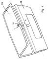
- in the illustrated embodiment serves the actuator for unlocking a rear window 37 of a motor vehicle, which in a pivotable tailgate 38 is provided. After unlocking the rear window 37 can be separated from the tailgate 38 be swung up.
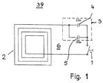
- a receiver 39 is provided on the rear window 37 of the motor vehicle a button 1 is provided, which is connected to a planar antenna 2 is. It is adjusted to a predetermined value via a matching element 3 Tuned resonance frequency. In the simplest and preferred Fall is the adjustment element 3 by two parallel Capacitors 4, 5 formed. You can be adjustable.
- the button 1 is pressed and thus the resonant circuit 6 closed.
- the resonance frequency 13,560 MHz.
- the resonance frequency be chosen differently.
- the resonant circuit 6 with the planar antenna 2 and the button 1 forms a passive antenna. It does not have to be powered.
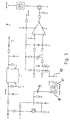
- the battery voltage which in the example is 12 volts, is determined by a voltage regulator 15 stabilized, in the embodiment to 7 volts.
- the input and the output of the controller 15 is in each case a resistor 35 and 36 assigned. That at the output of the controller 15 applied signal is fed to the plus input of the comparator 13, which is the controller signal with the rectified output signal of the oscillator 9 compares and delivers the control signal.
- the oscillator 9 has a transistor 16 which is connected via the quartz 11 in Resonance frequency preferably 13.560 MHz (ISM band) to the transmitting antenna 8 is brought. It is advantageously a planar antenna. you followed by two series-connected resistors 17, 18, a voltage divider to the base or to the working point of the Form transistor 16. Parallel to resistor 17 or in series with Resistor 18 has two capacitors 19, 20, which are used for the feedback are responsible for generating the vibration amplitude. A resistor 21 determines the emitter current to the transistor 16th
- the oscillator 9 is provided with a low-pass filter 22 from the outside to screen out incoming interference.
- the low pass 22 consists of a resistor 23, a capacitor 24 and a resistor 25 are subordinate.
- Resistor 25 is in the collector circuit of transistor 16 is connected and is in series with resistor 18 of the voltage divider.
- the rectifier 12 is advantageously temperature compensated so that the offset voltage of the comparator input not changed.
- the rectifier 12 is connected to this two diodes 26, 27 combined to form a unit, which are thermally integrated on a chip.
- the decoupling point 10 on the oscillator 9 is formed by a capacitor that is set that the voltage is still so high that it Threshold voltage of the rectifier 12 exceeds sufficiently far, in order to enable a reliable evaluation in the comparator 13.
- the decoupling point 10 of the oscillator 9 is a low-pass filter 28, 29 downstream to suppress RF interference from outside, which too could lead to an unwanted actuation of the control.
- the inductor 28 and the capacitor 29, which are the diodes, have a low pass 26, 27 are connected upstream.
- both the plus and A low-pass filter is connected upstream of the minus input of the comparator 13.
- the low pass assigned to the plus input consists of a Resistor 30 and a downstream capacitor 31st
- the low-pass filter assigned to the minus input of the comparator 13 has the resistor 32 and the downstream capacitor 33. Die have two resistors 30, 32 and the two capacitors 31, 33 same characteristics. At the comparator output 14 one low-resistance load 34 are operated.
- the resonance circuit 3 By pressing the button 1 of the passive element, the resonance circuit 3 closed, whereby 7 energy is removed from the transmitter becomes. It leads to the triggering of a control signal, which causes the unlocking of the rear window 37 is reached.
- the transfer between the passive element and the transmitter 7 are used the resonance frequency wired or wireless.
- the passive Secondary circuit 6, which is tuned to the transmission frequency or via the button 1 is detuned from the transmission frequency, deprives the Oscillator 9 in the resonance case sufficient energy so that the drop the RF voltage across the RF rectifier 12 to the following Comparator circuit is detected. It provides a corresponding one at output 14 Logic signal to control a power FET switch 40, with which the unlocking of the rear window 37 is reached becomes.
- the transmitter 7 Due to the wireless unlocking of the rear window 37 without use of lines, cables and the like results in a very easy assembly of the actuator. It is not prone to failure and is particularly wear-free.
- the transmitter 7 only needs a minimum current, which is, for example, only about 3 mA. As a result, the transmitter 7 can also be in the standby position for a long time be without the vehicle battery which transmitter is connected, too much energy is being drawn.
- the transmitter 7 with the central locking of the motor vehicle to couple. If the vehicle is centrally locked, it is too the transmitter 7 is switched off so that it does not require any current. Becomes the central locking is opened, the transmitter 7 is also switched on, so that it is ready for use. If the transmitter 7 via the central locking switched off, there is no possibility for unauthorized persons manipulate the transmitter 7 from the outside and the rear window 37 to open without authorization.
- Fig. 5 shows a transmitter 7, in which the quartz 11 resonates with a part of the antenna 8 and capacitors connected to it 41, 42 is. As a result, the load on the quartz 11 becomes low held. By tapping the antenna 8 (coil) on upper coil tap a higher useful amplitude. This allows the Sensitivity increased with low quartz load become.
- the senor is essentially the same as in the previous embodiment. It works the same as the previous one Embodiment.
Landscapes
- Engineering & Computer Science (AREA)
- Computer Networks & Wireless Communication (AREA)
- Physics & Mathematics (AREA)
- General Physics & Mathematics (AREA)
- Lock And Its Accessories (AREA)
Abstract
Description
Die Erfindung betrifft eine Betätigungsvorrichtung für Entriegelungseinrichtungen
von Fahrzeugen, vorzugsweise von Kraftfahrzeugen,
nach dem Oberbegriff des Anspruches 1.The invention relates to an actuating device for unlocking devices
of vehicles, preferably of motor vehicles,
according to the preamble of
Es ist bei Kraftfahrzeugen bekannt, in der Heckklappe eine Heckscheibe schwenkbar anzuordnen. Die Heckscheibe wird in der Schließstellung durch eine Entriegelungseinrichtung gesichert. Damit die Heckscheibe hochgeklappt werden kann, muß sie entriegelt werden. Hierfür ist an der Heckscheibe ein Betätigungselement vorgesehen, mit dem durch Drücken ein Relais der Steuerung betätigt wird. Es sorgt dafür, daß die Heckscheibe freigegeben wird und geöffnet werden kann. Die Verbindung zwischen dem Betätigungselement und der Steuerung erfolgt über Leitungen. Ihre Verlegung ist aufwendig und schwierig. Es sind hierbei Steckverbindungen erforderlich, die sich im Betrieb lockern oder gar lösen können. Dann läßt sich die Heckscheibe nicht mehr entriegeln.It is known in motor vehicles, a rear window in the tailgate to be arranged pivotably. The rear window is in the Locked position secured by an unlocking device. In order to the rear window can be folded up, it must be unlocked. For this purpose, an actuating element is provided on the rear window, with which a control relay is actuated by pressing. It ensures that the rear window is released and opened can be. The connection between the actuator and the control takes place via lines. Their laying is complex and difficult. Plug connections are required here can loosen or even loosen during operation. Then you can Do not unlock the rear window anymore.
Der Erfindung liegt die Aufgabe zugrunde, die gattungsgemäße Betätigungsvorrichtung so auszubilden, daß sie einfach montiert werden kann und ein Ausfall oder eine Störung der Entriegelung auch unter extremen Bedingungen zuverlässig vermieden wird. The invention is based, the generic actuator trained so that they are easy to assemble can and a failure or malfunction of the release even under extreme conditions is reliably avoided.
Diese Aufgabe wird bei der gattungsgemäßen Betätigungsvorrichtung
erfindungsgemäß mit den kennzeichnenden Merkmalen des Anspruches
1 gelöst.This task is in the generic actuator
according to the invention with the characterizing features of the
Bei der erfindungsgemäßen Betätigungsvorrichtung wird das Auslösesignal vom Betätigungselement drahtlos auf die Steuerung übertragen. Aufgrund dieser drahtlosen Entriegelung sind Leitungen, Kabel und dergleichen nicht notwendig. Dadurch ist eine sehr einfache Montage der Betätigungsvorrichtung gewährleistet. Sie ist darüber hinaus nicht störanfällig und insbesondere verschleißfrei. Ein Ausfall oder eine Störung der Entriegelung ist darum auch unter extremen Bedingungen ausgeschlossen.In the actuating device according to the invention, the trigger signal transmitted wirelessly from the actuator to the control. Because of this wireless unlocking, lines are cables and the like not necessary. This makes it a very simple one Assembly of the actuator guaranteed. It is above not susceptible to faults and especially wear-free. An outage or a disturbance of the unlocking is therefore also under extreme Conditions excluded.
Das Betätigungselement und die Steuerung haben nur geringen Abstand voneinander, so daß schon geringe Leistungen zur Übertragung des Signals ausreichen, um die Entriegelung vorzunehmen. So kann der Abstand zwischen dem Betätigungselement und der Steuerung beispielsweise nur 1 bis 2 cm betragen. Das Betätigungselement wird am zu entriegelnden Bauteil vorgesehen, während die Steuerung karosserieseitig am Fahrzeug angeordnet wird.The actuating element and the control are only a short distance away from each other, so that even low power for transmission of the signal are sufficient to carry out the unlocking. So can be the distance between the actuator and the controller for example, only 1 to 2 cm. The actuator is provided on the component to be unlocked while the Control is arranged on the vehicle body side.
Weitere Merkmale der Erfindung ergeben sich aus den weiteren Ansprüchen, der Beschreibung und den Zeichnungen.Further features of the invention result from the further claims, the description and the drawings.
Die Erfindung wird anhand zweier in den Zeichnungen dargestellter Ausführungsbeispiele näher erläutert. Es zeigen
- Fig. 1
- einen Empfänger einer erfindungsgemäßen Betätigungsvorrichtung,
- Fig. 2
- einen Schaltplan eines Senders der erfindungsgemäßen Betätigungsvorrichtung,
- Fig. 3
- eine Heckklappe mit einem in Schließstellung befindlichen Heckfensters eines Kraftfahrzeuges, das mit der erfindungsgemäßen Betätigungsvorrichtung versehen ist,
- Fig. 4
- das Heckfenster gemäß Fig. 3 in geöffneter Stellung,
- Fig. 5
- einen Schaltplan eines Senders einer zweiten Ausführungsform einer erfindungsgemäßen Betätigungsvorrichtung.
- Fig. 1
- a receiver of an actuating device according to the invention,
- Fig. 2
- 2 shows a circuit diagram of a transmitter of the actuating device according to the invention,
- Fig. 3
- a tailgate with a rear window of a motor vehicle in the closed position, which is provided with the actuating device according to the invention,
- Fig. 4
- 3 in the open position,
- Fig. 5
- a circuit diagram of a transmitter of a second embodiment of an actuating device according to the invention.
Die Betätigungsvorrichtung wird bei Kraftfahrzeugen eingesetzt und
dient dazu, beispielsweise ein Heckfenster 37 (Fig. 3 und 4) eines
Kraftfahrzeuges zu entriegeln. Die Betätigungsvorrichtung kann aber
auch zum Öffnen eines Kofferraumdeckels, einer Motorhaube oder
eines Handschuhfaches eines Kraftfahrzeuges eingesetzt werden. Im
dargestellten Ausführungsbeispiel dient die Betätigungsvorrichtung
zum Entriegeln einer Heckscheibe 37 eines Kraftfahrzeuges, die in
einer schwenkbaren Heckklappe 38 vorgesehen ist. Nach dem Entriegeln
kann die Heckscheibe 37 gegenüber der Heckklappe 38 gesondert
hochgeschwenkt werden.The actuator is used in motor vehicles and
serves, for example, a rear window 37 (FIGS. 3 and 4)
Unlock motor vehicle. The actuator can, however
also for opening a trunk lid, a bonnet or
a glove compartment of a motor vehicle are used. in the
illustrated embodiment serves the actuator
for unlocking a
An der Heckscheibe 37 des Kraftfahrzeuges ist ein Empfänger 39 mit
einem Taster 1 vorgesehen, der an eine Planarantenne 2 angeschlossen
ist. Sie wird über ein Abgleichelement 3 auf eine vorgegebene
Resonanzfrequenz abgestimmt. Im einfachsten und bevorzugten
Fall wird das Abgleichelement 3 durch zwei parallel liegende
Kondensatoren 4, 5 gebildet. Sie können einstellbar sein.A
Um die Heckscheibe 37 hochzuklappen, wird der Taster 1 gedrückt
und damit der Resonanzkreis 6 geschlossen. Im Beispielsfall beträgt
die Resonanzfrequenz 13.560 MHz. Je nach Einsatzfall kann die Resonanzfrequenz
auch anders gewählt sein. In order to fold up the
Der Resonanzkreis 6 mit der Planarantenne 2 und dem Taster 1 bildet
eine passive Antenne. Sie muß nicht mit Strom versorgt werden.The
Sobald der Resonanzkreis 6 durch Drücken des Tasters 1 geschlossen
wird, wird einer in einem Sender 7 der Betätigungsvorrichtung
befindlichen Sendeantenne 8 Energie entzogen. Dadurch wird die
Amplitude eines nachgeschalteten Oszillators 9 an einem hochohmigen
Auskoppelungspunkt 10 eines Quarzes 11 herabgesetzt. Die
Hochfrequenzspannung wird an einem Hochfrequenzgleichrichter 12
gleichgerichtet und dem Minuseingang eines Komparators 13 zugeführt.
Aufgrund des Amplitudenabfalles am Auskoppelungspunkt 3
sinkt der Pegel am Plusausgang 14 des dem Gleichrichter 12 nachgeschalteten
Komparators 13, so daß am Ausgang 14 des Komparators
13 das entsprechende Steuersignal zur Entriegelung des Heckscheibenfensters
ansteht.As soon as the
Die Batteriespannung, die im Beispielsfall 12 Volt beträgt, wird mittels
eines Spannungsreglers 15 stabilisiert, im Ausführungsbeispiel
auf 7 Volt. Dem Eingang und dem Ausgang des Reglers 15 ist jeweils
ein Widerstand 35 und 36 zugeordnet. Das am Ausgang des Reglers
15 anliegende Signal wird dem Pluseingang des Komparators 13 zugeführt,
der das Reglersignal mit dem gleichgerichteten Ausgangssignal
des Oszillators 9 vergleicht und das Steuersignal liefert.The battery voltage, which in the example is 12 volts, is determined by
a
Der Oszillator 9 hat einen Transistor 16, der über den Quarz 11 in
Resonanzfrequenz vorzugsweise 13,560 MHz (ISM-Band) zur Sendeantenne
8 gebracht wird. Sie ist vorteilhaft eine Planarantenne. Ihr
nachgeschaltet sind zwei in Reihe geschaltete Widerstände 17, 18,
die einen Spannungsteiler zur Basis bzw. zum Arbeitspunkt des
Transistors 16 bilden. Parallel zum Widerstand 17 bzw. in Reihe zum
Widerstand 18 liegen zwei Kondensatoren 19, 20, die für die Rückkoppelung
verantwortlich sind, um die Schwingungsamplitude zu erzeugen.
Ein Widerstand 21 bestimmt den Emitterstrom zum Transistor
16.The
Der Oszillator 9 ist mit einem Tiefpaß 22 versehen, um von außen
kommende Störstrahlungen auszusieben. Der Tiefpaß 22 besteht aus
einem Widerstand 23, dem ein Kondensator 24 und ein Widerstand
25 nachgeordnet sind. Der Widerstand 25 ist in den Kollektorkreis
des Transistors 16 geschaltet und liegt in Reihe zum Widerstand 18
des Spannungsteilers.The
Der Gleichrichter 12 ist vorteilhaft temperaturkompensiert, so daß
sich bei Temperaturschwankungen die Offset-Spannung des Komparatoreinganges
nicht verändert. Hierzu ist der Gleichrichter 12 mit
zwei zu einer Einheit zusammengefaßten Dioden 26, 27 versehen,
die thermisch auf einem Chip integriert sind. Die Auskopplungsstelle
10 am Oszillator 9 wird durch einen Kondensator gebildet, der so
eingestellt ist, daß die Spannung noch so hoch ist, daß sie die
Schwellspannung des Gleichrichters 12 ausreichend weit übersteigt,
um eine zuverlässige Auswertung im Komparator 13 zu ermöglichen.The
Dem Auskoppelungspunkt 10 des Oszillators 9 ist ein Tiefpaß 28, 29
nachgeschaltet, um HF-Störungen von außen zu unterdrücken, die zu
einer ungewollten Betätigung der Steuerung führen könnten. Der
Tiefpaß hat die Induktivität 28 und den Kondensator 29, die den Dioden
26, 27 vorgeschaltet sind.The
Im dargestellten Ausführungsbeispiel ist sowohl dem Plus- als auch
dem Minuseingang des Komparators 13 jeweils ein Tiefpaß vorgeschaltet.
Der dem Pluseingang zugeordnete Tiefpaß besteht aus einem
Widerstand 30 und einem nachgeschalteten Kondensator 31.
Der dem Minuseingang des Komparators 13 zugeordnete Tiefpaß hat
den Widerstand 32 und den nachgeschalteten Kondensator 33. Die
beiden Widerstände 30, 32 und die beiden Kondensatoren 31, 33 haben
gleiche Kenndaten. An dem Komparatorausgang 14 kann eine
niederohmige Last 34 betrieben werden.In the illustrated embodiment, both the plus and
A low-pass filter is connected upstream of the minus input of the
Durch Drücken des Tasters 1 des Passivelementes wird der Resonanzkreis
3 geschlossen, wodurch dem Sender 7 Energie entzogen
wird. Sie führt zum Auslösen eines Steuersignales, wodurch die Entriegelung
des Heckfensters 37 erreicht wird. Die Übertragung zwischen
dem passiven Element und dem Sender 7 erfolgt unter Ausnutzung
der Resonanzfrequenz leitungs- bzw. drahtlos. Der passive
Sekundärkreis 6, der auf die Sendefrequenz abgestimmt bzw. über
den Taster 1 gegen die Sendefrequenz verstimmt ist, entzieht dem
Oszillator 9 im Resonanzfall ausreichend Energie, so daß der Abfall
der HF-Spannung über den HF-Gleichrichter 12 auf die folgende
Komparatorschaltung erfaßt wird. Sie liefert am Ausgang 14 ein entsprechendes
Logiksignal zur Steuerung eines Leistungs-FET-Schalters
40, mit dem die Entriegelung des Heckfensters 37 erreicht
wird.By pressing the
Aufgrund der drahtlosen Entriegelung des Heckfensters 37 ohne Verwendung
von Leitungen, Kabeln und dergleichen ergibt sich eine sehr
einfache Montage der Betätigungsvorrichtung. Sie ist nicht störanfällig
und ist insbesondere verschleißfrei. De Sender 7 benötigt nur
einen minimalen Strom, der beispielsweise nur etwa 3 mA beträgt.
Dadurch kann der Sender 7 auch über lange Zeit hinweg in Bereitschaftsstellung
sein, ohne daß dadurch der Fahrzeugbatterie, an
welche der Sender angeschlossen ist, zu viel Energie entzogen wird.Due to the wireless unlocking of the
Vorteilhaft ist es, den Sender 7 mit der Zentralverriegelung des Kraftfahrzeuges
zu koppeln. Ist das Fahrzeug zentralverriegelt, ist auch
der Sender 7 ausgeschaltet, so daß er keinen Strom benötigt. Wird
die Zentralverriegelung geöffnet, wird auch der Sender 7 eingeschaltet,
so daß er betriebsbereit ist. Wird der Sender 7 über die Zentralverriegelung
abgeschaltet, besteht für Unbefugte keine Möglichkeit,
von außen den Sender 7 zu manipulieren und das Heckfenster 37
unbefugt zu öffnen.It is advantageous to the
Fig. 5 zeigt einen Sender 7, bei dem der Quarz 11 in Resonanz mit
einem Teil der Antenne 8 und an sie angeschlossenen Kondensatoren
41, 42 ist. Dadurch wird die Belastung des Quarzes 11 gering
gehalten. Durch die Anzapfung der Antenne 8 (Spule) entsteht am
oberen Spulenabgriff eine höhere Nutzamplitude. Dadurch kann die
Empfindlichkeit bei gleichzeitig geringer Quarzbelastung gesteigert
werden.Fig. 5 shows a
Im übrigen ist der Sensor im wesentlichen gleich ausgebildet wie bei der vorigen Ausführungsform. Er arbeitet gleich wie beim vorhergehenden Ausführungsbeispiel.Otherwise, the sensor is essentially the same as in the previous embodiment. It works the same as the previous one Embodiment.
Claims (13)
dadurch gekennzeichnet, daß das Betätigungselement (1) das Signal drahtlos der Steuerung (7) zuführt.Actuating device for unlocking devices of vehicles, preferably of motor vehicles, with at least one actuating element which emits a signal to a control for unlocking when actuated,
characterized in that the actuating element (1) wirelessly feeds the signal to the controller (7).
dadurch gekennzeichnet, daß das Betätigungselement (1) ein Taster ist.Device according to claim 1,
characterized in that the actuating element (1) is a button.
dadurch gekennzeichnet, daß das Betätigungselement (1) Teil eines passiven Empfängers ist, der vorteilhaft eine vorzugsweise als Planarantenne ausgebildete Passivantenne (2) aufweist.Device according to claim 1 or 2,
characterized in that the actuating element (1) is part of a passive receiver which advantageously has a passive antenna (2) which is preferably designed as a planar antenna.
dadurch gekennzeichnet, daß die Passivantenne (2) in einem Resonanzkreis liegt, der vorzugsweise durch Betätigen des Betätigungselementes (1) geschlossen wird.Device according to claim 3 or 4,
characterized in that the passive antenna (2) lies in a resonant circuit which is preferably closed by actuating the actuating element (1).
dadurch gekennzeichnet, daß zur Abstimmung der Passivantenne (2) auf die Resonanzfrequenz ein Abstimmelement (3) vorgesehen ist, das vorteilhaft zwei parallel zueinander liegende Kondensatoren (4, 5) aufweist.Device according to claim 4,
characterized in that a tuning element (3) is provided for tuning the passive antenna (2) to the resonance frequency, which advantageously has two capacitors (4, 5) lying parallel to one another.
dadurch gekennzeichnet, daß die Steuerung (7) wenigstens eine Antenne (8), vorzugsweise eine Planarantenne, aufweist, der vorteilhaft durch Betätigen des Betätigungselementes (1) Energie entzogen wird.Device according to one of claims 1 to 5,
characterized in that the control (7) has at least one antenna (8), preferably a planar antenna, from which energy is advantageously extracted by actuating the actuating element (1).
dadurch gekennzeichnet, daß die Antenne (8) Teil eines Oszillators (9) ist, der vorteilhaft ein Schaltelement (16), vorzugsweise einen Transistor, aufweist.Apparatus according to claim 6,
characterized in that the antenna (8) is part of an oscillator (9) which advantageously has a switching element (16), preferably a transistor.
dadurch gekennzeichnet, daß das Schaltelement (16) über einen Quarz (11) in Resonanz zur Antenne (8) gebracht wird.Device according to claim 7,
characterized in that the switching element (16) is brought into resonance with the antenna (8) via a quartz (11).
dadurch gekennzeichnet, daß dem Oszillator (9) ein Gleichrichter (12) nachgeschaltet ist, dessen Ausgangssignal vorteilhaft einem Komparator (13) zugeführt wird.Device according to claim 7 or 8,
characterized in that the oscillator (9) is followed by a rectifier (12), the output signal of which is advantageously fed to a comparator (13).
dadurch gekennzeichnet, daß die Ausgangsspannung des Oszillators (9) herabgesetzt und dem Komparator (13) zugeführt wird, der vorteilhaft das Ausgangssignal des Gleichrichters (12) mit einem Reglersignal vergleicht. Device according to one of claims 6 to 10,
characterized in that the output voltage of the oscillator (9) is reduced and fed to the comparator (13) which advantageously compares the output signal of the rectifier (12) with a regulator signal.
dadurch gekennzeichnet, daß das Ausgangssignal des Komparators (13) zur Entriegelung herangezogen wird.Device according to one of claims 9 to 11,
characterized in that the output signal of the comparator (13) is used for unlocking.
dadurch gekennzeichnet, daß eine Auskoppelungsstelle des Oszillators (9) durch einen Kondensator (10) gebildet ist, der vorteilhaft die Spannung oberhalb der Schwellspannung des Gleichrichters (12) hält.Device according to one of claims 7 to 12,
characterized in that a decoupling point of the oscillator (9) is formed by a capacitor (10) which advantageously keeps the voltage above the threshold voltage of the rectifier (12).
Applications Claiming Priority (2)
| Application Number | Priority Date | Filing Date | Title |
|---|---|---|---|
| DE10104377 | 2001-02-01 | ||
| DE10104377A DE10104377A1 (en) | 2001-02-01 | 2001-02-01 | Actuating device for unlocking devices of vehicles, preferably of motor vehicles |
Publications (3)
| Publication Number | Publication Date |
|---|---|
| EP1229191A2 true EP1229191A2 (en) | 2002-08-07 |
| EP1229191A3 EP1229191A3 (en) | 2002-08-14 |
| EP1229191B1 EP1229191B1 (en) | 2004-11-17 |
Family
ID=7672389
Family Applications (1)
| Application Number | Title | Priority Date | Filing Date |
|---|---|---|---|
| EP02001769A Expired - Lifetime EP1229191B1 (en) | 2001-02-01 | 2002-01-25 | Actuating device for unlocking devices for vehicles, in particular motor vehicles |
Country Status (3)
| Country | Link |
|---|---|
| US (1) | US6794767B2 (en) |
| EP (1) | EP1229191B1 (en) |
| DE (2) | DE10104377A1 (en) |
Cited By (2)
| Publication number | Priority date | Publication date | Assignee | Title |
|---|---|---|---|---|
| FR2909340A1 (en) * | 2006-11-30 | 2008-06-06 | Peugeot Citroen Automobiles Sa | Opening rear window for motor vehicle, has supply terminals of electrical conductors, defrosting heating assembly and locking control unit arranged on separate places that are provided on glazed surface in distinct humid zones |
| FR2911899A1 (en) * | 2007-01-30 | 2008-08-01 | Peugeot Citroen Automobiles Sa | Motor vehicle, has rods coupling knob and push button, when window is displaced to closed position, so that button detects movement of knob between rest and unlocking positions and uncoupling knob and button, when window is in open position |
Families Citing this family (4)
| Publication number | Priority date | Publication date | Assignee | Title |
|---|---|---|---|---|
| US7121605B2 (en) * | 2004-03-17 | 2006-10-17 | Lear Corporation | Glove box with sensor |
| DE102004059214B4 (en) | 2004-12-09 | 2018-07-26 | Volkswagen Ag | Arrangement for a motor vehicle with an installation disk, a lock and means for electromotive unlocking the lock |
| DE102009045830A1 (en) | 2009-10-20 | 2011-07-07 | ZF Friedrichshafen AG, 88046 | Interlocking device i.e. engine bonnet lock, for motor vehicle, has energy converter converting movement of interlocking elements into electrical energy that is utilized for transmitting status of interlocking mechanism to control system |
| WO2012024651A1 (en) * | 2010-08-20 | 2012-02-23 | Stoneridge Control Devices, Inc. | Integrated release switch assembly |
Family Cites Families (18)
| Publication number | Priority date | Publication date | Assignee | Title |
|---|---|---|---|---|
| US4325058A (en) * | 1980-06-11 | 1982-04-13 | Gentex Corporation | Pre-intrusion detection and alarm system |
| FR2598006B1 (en) * | 1986-04-28 | 1989-01-13 | Signalisation | PRESENCE DETECTOR, NEAR A CONTROL STATION, AN ANSWERING MACHINE ASSOCIATED WITH A CARRIER |
| US4897643A (en) * | 1986-08-11 | 1990-01-30 | Mazda Motor Corporation | Vehicular electronic equipment with door lock and side window antenna |
| US5189839A (en) * | 1990-03-22 | 1993-03-02 | Masco Industries, Inc. | Control apparatus for powered vehicle door systems |
| US5402132A (en) * | 1992-05-29 | 1995-03-28 | Mcdonnell Douglas Corporation | Monopole/crossed slot single antenna direction finding system |
| US5375811A (en) * | 1994-01-19 | 1994-12-27 | Marotta Scientific Controls, Inc. | Magnetic-latching valve |
| FR2723238B1 (en) * | 1994-07-27 | 1996-09-13 | Suisse Electronique Microtech | COMMUNICATION SYSTEM BETWEEN A BASE STATION AND A PASSIVE TRANSPONDER |
| US5541588A (en) * | 1994-08-01 | 1996-07-30 | Metrol Co., Ltd. | Control signal transfer device for a position detecting sensor |
| JP3434934B2 (en) * | 1995-06-07 | 2003-08-11 | 株式会社デンソー | Wireless vehicle control system |
| GB2302559B (en) * | 1995-06-23 | 1998-06-03 | Draftex Ind Ltd | Opening arrangements and methods for closure members |
| US5694115A (en) * | 1996-06-11 | 1997-12-02 | Desatoff; Jack | Remote control activated electric drip coffee maker |
| DE19632025C2 (en) * | 1996-08-08 | 1998-07-23 | Daimler Benz Ag | Authentication device with electronic authentication communication |
| US5869969A (en) * | 1996-11-13 | 1999-02-09 | Northern Telecom Limited | Battery charger/rectifier voltage temperature compensation circuit including protection and diagnostic scheme |
| US5942977A (en) * | 1997-08-13 | 1999-08-24 | Ludwig Kipp | Radio transponder |
| DE19752029B4 (en) * | 1997-11-24 | 2004-02-26 | Siemens Ag | Anti-theft system for a motor vehicle |
| US6268796B1 (en) * | 1997-12-12 | 2001-07-31 | Alfred Gnadinger | Radio frequency identification transponder having integrated antenna |
| EP0978729A3 (en) * | 1998-08-07 | 2002-03-20 | Hitachi, Ltd. | High-frequency transmitter-receiving apparatus for such an application as vehicle-onboard radar system |
| DE19927179B4 (en) * | 1999-06-15 | 2005-01-20 | Daimlerchrysler Ag | Device for opening a luggage compartment of a motor vehicle |
-
2001
- 2001-02-01 DE DE10104377A patent/DE10104377A1/en not_active Withdrawn
-
2002
- 2002-01-25 EP EP02001769A patent/EP1229191B1/en not_active Expired - Lifetime
- 2002-01-25 DE DE50201535T patent/DE50201535D1/en not_active Expired - Lifetime
- 2002-01-30 US US10/062,579 patent/US6794767B2/en not_active Expired - Fee Related
Non-Patent Citations (1)
| Title |
|---|
| None |
Cited By (3)
| Publication number | Priority date | Publication date | Assignee | Title |
|---|---|---|---|---|
| FR2909340A1 (en) * | 2006-11-30 | 2008-06-06 | Peugeot Citroen Automobiles Sa | Opening rear window for motor vehicle, has supply terminals of electrical conductors, defrosting heating assembly and locking control unit arranged on separate places that are provided on glazed surface in distinct humid zones |
| FR2911899A1 (en) * | 2007-01-30 | 2008-08-01 | Peugeot Citroen Automobiles Sa | Motor vehicle, has rods coupling knob and push button, when window is displaced to closed position, so that button detects movement of knob between rest and unlocking positions and uncoupling knob and button, when window is in open position |
| EP1953316A1 (en) * | 2007-01-30 | 2008-08-06 | Peugeot Citroën Automobiles S.A. | Automobile and device for controlling the unlocking of a window for this vehicle. |
Also Published As
| Publication number | Publication date |
|---|---|
| EP1229191B1 (en) | 2004-11-17 |
| EP1229191A3 (en) | 2002-08-14 |
| DE50201535D1 (en) | 2004-12-23 |
| US6794767B2 (en) | 2004-09-21 |
| DE10104377A1 (en) | 2002-08-08 |
| US20020162408A1 (en) | 2002-11-07 |
Similar Documents
| Publication | Publication Date | Title |
|---|---|---|
| EP1328695B1 (en) | Device for initiating an opening and closing process in a motor vehicle | |
| EP2567049B1 (en) | Function activating method and device for a vehicle | |
| DE60121081T2 (en) | Security system for enabling authenticated access of a person to a secured room | |
| EP1216165B1 (en) | Wireless data and energy transmission device | |
| WO1992018732A1 (en) | Device for operating a door locking and/or alarm installation | |
| EP4066384B1 (en) | Apparatus for a vehicle for detecting an activation action in at least two different detection regions | |
| DE102013104724A1 (en) | Security system with an accident detection sensor | |
| DE102006042976A1 (en) | Access arrangement for a vehicle | |
| EP2098670B1 (en) | Motor vehicle with a vehicle component which can automatically be adjusted to an open or closed position | |
| EP3395621A1 (en) | Control method and control system for a vehicle locking element | |
| EP1229191B1 (en) | Actuating device for unlocking devices for vehicles, in particular motor vehicles | |
| DE4316867A1 (en) | Door-actuating device | |
| EP2098672A1 (en) | Motor vehicle with a vehicle component which can automatically be adjusted to an open or closed position | |
| DE10222186C1 (en) | Safety switch has comparator providing switch signal if energy induced in receiver element during period following electromagnetic signal emission exceeds/falls below predefined threshold | |
| DE10004616B4 (en) | Circuit arrangement for a transmitting and / or receiving device | |
| DE102008062627A1 (en) | System and method for remote activation using a transmitter-switch arrangement | |
| EP1466789B1 (en) | Remote Control System | |
| DE102006046437B4 (en) | Device for monitoring the state of a safety-related device | |
| DE102020118567A1 (en) | Device for a vehicle for communication with a mobile device | |
| EP1533450B1 (en) | A motor vehicle locking system | |
| DE102004039835B3 (en) | Electronic access system for motor vehicle combines retrofitted passive electronic access system with remote access system already in vehicle | |
| DE19745617C2 (en) | Motor vehicle with a locking system that can be opened or locked by means of a remote control | |
| DE10360418A1 (en) | A method for remotely operating the door locks of a motor vehicle, each lock associated with an electric actuator and electronic control board and a communicating hand control unit | |
| DE102018125176B4 (en) | Door handle module with an NFC initiator | |
| DE4205271C1 (en) | Control circuit for central locking installation - uses switch to change potential to change state of control switch for remote operation of motor vehicle doors or boot |
Legal Events
| Date | Code | Title | Description |
|---|---|---|---|
| PUAI | Public reference made under article 153(3) epc to a published international application that has entered the european phase |
Free format text: ORIGINAL CODE: 0009012 |
|
| PUAL | Search report despatched |
Free format text: ORIGINAL CODE: 0009013 |
|
| AK | Designated contracting states |
Kind code of ref document: A2 Designated state(s): AT BE CH CY DE DK ES FI FR GB GR IE IT LI LU MC NL PT SE TR |
|
| AX | Request for extension of the european patent |
Free format text: AL;LT;LV;MK;RO;SI |
|
| AK | Designated contracting states |
Kind code of ref document: A3 Designated state(s): AT BE CH CY DE DK ES FI FR GB GR IE IT LI LU MC NL PT SE TR |
|
| AX | Request for extension of the european patent |
Free format text: AL;LT;LV;MK;RO;SI |
|
| 17P | Request for examination filed |
Effective date: 20021126 |
|
| AKX | Designation fees paid |
Designated state(s): DE |
|
| 17Q | First examination report despatched |
Effective date: 20030703 |
|
| GRAP | Despatch of communication of intention to grant a patent |
Free format text: ORIGINAL CODE: EPIDOSNIGR1 |
|
| GRAS | Grant fee paid |
Free format text: ORIGINAL CODE: EPIDOSNIGR3 |
|
| GRAA | (expected) grant |
Free format text: ORIGINAL CODE: 0009210 |
|
| RTI1 | Title (correction) |
Free format text: ACTUATING DEVICE FOR UNLOCKING DEVICES FOR VEHICLES, IN PARTICULAR MOTOR VEHICLES |
|
| AK | Designated contracting states |
Kind code of ref document: B1 Designated state(s): DE |
|
| REG | Reference to a national code |
Ref country code: IE Ref legal event code: FG4D Free format text: GERMAN |
|
| REF | Corresponds to: |
Ref document number: 50201535 Country of ref document: DE Date of ref document: 20041223 Kind code of ref document: P |
|
| REG | Reference to a national code |
Ref country code: IE Ref legal event code: FD4D |
|
| PLBE | No opposition filed within time limit |
Free format text: ORIGINAL CODE: 0009261 |
|
| STAA | Information on the status of an ep patent application or granted ep patent |
Free format text: STATUS: NO OPPOSITION FILED WITHIN TIME LIMIT |
|
| 26N | No opposition filed |
Effective date: 20050818 |
|
| PGFP | Annual fee paid to national office [announced via postgrant information from national office to epo] |
Ref country code: DE Payment date: 20210326 Year of fee payment: 20 |
|
| REG | Reference to a national code |
Ref country code: DE Ref legal event code: R071 Ref document number: 50201535 Country of ref document: DE |