EP1229295A2 - Wärmeübertrager - Rohrblock mit mehreren geschlitzen Sammelrohren - Google Patents
Wärmeübertrager - Rohrblock mit mehreren geschlitzen Sammelrohren Download PDFInfo
- Publication number
- EP1229295A2 EP1229295A2 EP01130534A EP01130534A EP1229295A2 EP 1229295 A2 EP1229295 A2 EP 1229295A2 EP 01130534 A EP01130534 A EP 01130534A EP 01130534 A EP01130534 A EP 01130534A EP 1229295 A2 EP1229295 A2 EP 1229295A2
- Authority
- EP
- European Patent Office
- Prior art keywords
- tube
- openings
- manifolds
- header
- block
- Prior art date
- Legal status (The legal status is an assumption and is not a legal conclusion. Google has not performed a legal analysis and makes no representation as to the accuracy of the status listed.)
- Granted
Links
- 238000004378 air conditioning Methods 0.000 abstract description 4
- 238000009434 installation Methods 0.000 abstract 1
- WYTGDNHDOZPMIW-RCBQFDQVSA-N alstonine Natural products C1=CC2=C3C=CC=CC3=NC2=C2N1C[C@H]1[C@H](C)OC=C(C(=O)OC)[C@H]1C2 WYTGDNHDOZPMIW-RCBQFDQVSA-N 0.000 description 10
- 239000012530 fluid Substances 0.000 description 3
- 238000003780 insertion Methods 0.000 description 3
- 230000037431 insertion Effects 0.000 description 3
- 238000000034 method Methods 0.000 description 3
- 239000003507 refrigerant Substances 0.000 description 3
- 238000007789 sealing Methods 0.000 description 3
- 238000005476 soldering Methods 0.000 description 3
- 238000005452 bending Methods 0.000 description 2
- 210000001503 joint Anatomy 0.000 description 2
- 238000003754 machining Methods 0.000 description 2
- 239000000463 material Substances 0.000 description 2
- 239000002184 metal Substances 0.000 description 2
- 229910000679 solder Inorganic materials 0.000 description 2
- 238000004891 communication Methods 0.000 description 1
- 238000010276 construction Methods 0.000 description 1
- 239000011888 foil Substances 0.000 description 1
- 210000001061 forehead Anatomy 0.000 description 1
- 238000003801 milling Methods 0.000 description 1
- 238000005096 rolling process Methods 0.000 description 1
- 238000004804 winding Methods 0.000 description 1
Images

Classifications
-
- F—MECHANICAL ENGINEERING; LIGHTING; HEATING; WEAPONS; BLASTING
- F28—HEAT EXCHANGE IN GENERAL
- F28F—DETAILS OF HEAT-EXCHANGE AND HEAT-TRANSFER APPARATUS, OF GENERAL APPLICATION
- F28F9/00—Casings; Header boxes; Auxiliary supports for elements; Auxiliary members within casings
- F28F9/02—Header boxes; End plates
- F28F9/04—Arrangements for sealing elements into header boxes or end plates
- F28F9/16—Arrangements for sealing elements into header boxes or end plates by permanent joints, e.g. by rolling
- F28F9/18—Arrangements for sealing elements into header boxes or end plates by permanent joints, e.g. by rolling by welding
-
- F—MECHANICAL ENGINEERING; LIGHTING; HEATING; WEAPONS; BLASTING
- F28—HEAT EXCHANGE IN GENERAL
- F28D—HEAT-EXCHANGE APPARATUS, NOT PROVIDED FOR IN ANOTHER SUBCLASS, IN WHICH THE HEAT-EXCHANGE MEDIA DO NOT COME INTO DIRECT CONTACT
- F28D1/00—Heat-exchange apparatus having stationary conduit assemblies for one heat-exchange medium only, the media being in contact with different sides of the conduit wall, in which the other heat-exchange medium is a large body of fluid, e.g. domestic or motor car radiators
- F28D1/02—Heat-exchange apparatus having stationary conduit assemblies for one heat-exchange medium only, the media being in contact with different sides of the conduit wall, in which the other heat-exchange medium is a large body of fluid, e.g. domestic or motor car radiators with heat-exchange conduits immersed in the body of fluid
- F28D1/04—Heat-exchange apparatus having stationary conduit assemblies for one heat-exchange medium only, the media being in contact with different sides of the conduit wall, in which the other heat-exchange medium is a large body of fluid, e.g. domestic or motor car radiators with heat-exchange conduits immersed in the body of fluid with tubular conduits
- F28D1/047—Heat-exchange apparatus having stationary conduit assemblies for one heat-exchange medium only, the media being in contact with different sides of the conduit wall, in which the other heat-exchange medium is a large body of fluid, e.g. domestic or motor car radiators with heat-exchange conduits immersed in the body of fluid with tubular conduits the conduits being bent, e.g. in a serpentine or zig-zag
- F28D1/0477—Heat-exchange apparatus having stationary conduit assemblies for one heat-exchange medium only, the media being in contact with different sides of the conduit wall, in which the other heat-exchange medium is a large body of fluid, e.g. domestic or motor car radiators with heat-exchange conduits immersed in the body of fluid with tubular conduits the conduits being bent, e.g. in a serpentine or zig-zag the conduits being bent in a serpentine or zig-zag
- F28D1/0478—Heat-exchange apparatus having stationary conduit assemblies for one heat-exchange medium only, the media being in contact with different sides of the conduit wall, in which the other heat-exchange medium is a large body of fluid, e.g. domestic or motor car radiators with heat-exchange conduits immersed in the body of fluid with tubular conduits the conduits being bent, e.g. in a serpentine or zig-zag the conduits being bent in a serpentine or zig-zag the conduits having a non-circular cross-section
-
- F—MECHANICAL ENGINEERING; LIGHTING; HEATING; WEAPONS; BLASTING
- F28—HEAT EXCHANGE IN GENERAL
- F28F—DETAILS OF HEAT-EXCHANGE AND HEAT-TRANSFER APPARATUS, OF GENERAL APPLICATION
- F28F9/00—Casings; Header boxes; Auxiliary supports for elements; Auxiliary members within casings
- F28F9/02—Header boxes; End plates
- F28F9/0202—Header boxes having their inner space divided by partitions
- F28F9/0204—Header boxes having their inner space divided by partitions for elongated header box, e.g. with transversal and longitudinal partitions
- F28F9/0214—Header boxes having their inner space divided by partitions for elongated header box, e.g. with transversal and longitudinal partitions having only longitudinal partitions
-
- F—MECHANICAL ENGINEERING; LIGHTING; HEATING; WEAPONS; BLASTING
- F28—HEAT EXCHANGE IN GENERAL
- F28F—DETAILS OF HEAT-EXCHANGE AND HEAT-TRANSFER APPARATUS, OF GENERAL APPLICATION
- F28F9/00—Casings; Header boxes; Auxiliary supports for elements; Auxiliary members within casings
- F28F9/02—Header boxes; End plates
- F28F9/0243—Header boxes having a circular cross-section
-
- F—MECHANICAL ENGINEERING; LIGHTING; HEATING; WEAPONS; BLASTING
- F28—HEAT EXCHANGE IN GENERAL
- F28F—DETAILS OF HEAT-EXCHANGE AND HEAT-TRANSFER APPARATUS, OF GENERAL APPLICATION
- F28F2220/00—Closure means, e.g. end caps on header boxes or plugs on conduits
Definitions
- the invention relates to a heat exchanger tube block with at least two collector tubes with a C-shaped cross section, which each have a continuous longitudinal slot, and with flat tubes inserted into the longitudinal tube slots.
- Pipe blocks of this type are used, for example, for heat exchangers used in automotive air conditioning systems.
- Heat exchanger tube block described which is a stack of rectilinear Includes flat tubes, each end in one Longitudinal slot of two header pipes are inserted, which are parallel arranged along two opposing sides of the block are.
- the header pipes can be made from a respective Tube blank into which the continuous longitudinal slot is cut by milling or the like is introduced, or by bending one each sheet metal strip in the desired C-cross-sectional shape be made.
- the invention is a technical problem of providing a new type of heat exchanger tube block of the type mentioned Type based on which is relatively small Effort with the required fluid tightness and pressure resistance can be made.
- the invention solves this problem by providing a Heat exchanger tube blocks with the features of the claim 1.
- the pipe block according to the invention includes an end plate element, which has several C-shaped openings and plugged onto one end side of the at least two manifolds is, each of these manifolds fluid-tight into one the openings are inserted.
- the C-shaped header section suitable C-contour of the openings enables without any problems the fluid-tight insertion of the header pipes into the openings, by placing the end plate element on the header pipes is pushed on and the respective manifold through the associated opening passes, after which the remaining Gap between the collecting tube and the opening edge, for example by means of Soldering is sealed in a fluid-tight manner.
- header pipes have a continuous longitudinal slot, you can, if required, without machining the pipe alone made from a flat blank by a bending process become.
- heat exchanger tube block includes another end plate element, the several Has openings for inserting a respective manifold and on the other end side of the at least two manifolds is plugged in, the openings being designed such that the internal flow cross-section of the push-through manifolds at least partially leave blank.
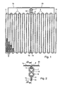
- the tube / fin block shown in FIG. 1 can be used, for example, for an evaporator of a motor vehicle air conditioning system, and it can be designed without any problems with a pressure resistance which is required for systems which work with the refrigerant CO 2 .
- the tube / fin block is of the flat tube serpentine type and contains two serpentine multi-chamber flat tubes 1, 2, which are arranged side by side between two side end plates 3, 4. Heat-conducting corrugated fins 5 are introduced in a conventional manner between the individual serpentine windings of the flat tubes 1, 2.
- the two serpentine flat tubes border in the center of the block 1, 2 with their inner end sections 1a, 2a Touching each other.
- the two contiguous Flat tube end sections 1a, 2a open at the top in FIG. 1 Block side in a first manifold 6 with a C-shaped cross section.
- the other, outer end sections 1b, 2b of the two Serpentine flat tubes 1, 2 are led out on the upper block side, by a first right-angled bend towards each other to the inside and in the middle of the block by a second bend down and into a second manifold 7 inserted with a C-shaped cross section, which with a small Distance above the first manifold 6 parallel to this is arranged.
- the collecting tubes 6, 7 have to accommodate the flat tube ends each have a continuous longitudinal slot 10, 11. Latter can be manufactured very easily without machining can be realized in that the two manifolds 6, 7 by a forming round rolling process from one plan sheet metal strips are made to the desired C cross-sectional shape while leaving the respective continuous Longitudinal slot 10, 11 is bent. This brings savings work processes and also avoids the risk of that chips get into the inside of the collecting tube and later Operation can lead to blockages in the refrigerant circuit. Solder-plated material is preferred for the header pipes 6, 7 used.
- each of the two header ends 12, 13 provided in the example shown are realized as 8-shaped, perforated plates.
- the 4 and 5 show the two end plates 12, 13 in Individual representation. From this it can be seen that they are fulfilling are punched differently for different purposes.
- the one end plate 12 shown in FIG. 4 is included two C-shaped through openings 14, 15 provided which the C-shaped cross-sectional contour of the manifolds 6, 7 and in their mutual position of the relative position of the two manifolds 6, 7 correspond to each other.
- This first end plate In this way, 12 serves as an axially fluid-tight closure Element. For this, it will be on the right in Fig. 3 Front of the two header pipes lying parallel to each other 6, 7 pushed until it is against the side in the manifolds 6, 7 inserted flat tube ends, the Collecting tubes 6, 7 through the through-openings with the same cross-sectional shape 14, 15 pass through.
- Front ends of the two manifolds 6, 7 is, as in Fig. 3rd shown, one connecting tube 18 widened at the end, 19 axially pushed on.
- the connecting pipes 18, 19 meet with its forehead butt against the end plate 13, that in turn with a butt joint against the in the manifolds 6, 7 inserted flat tube ends.
- These butt joint connections fill up during the soldering process, in which the entire Pipe block complex is soldered tight, fluid-tight with solder.
- the end plates 12, 13 preferably also exist made of solder-plated material.
- the other end plate 13 leaves its circular through openings 16, 17 the inner Flow cross section of the two manifolds 6, 7 free, so that on the corresponding connection side on the left in FIG. 3 undisturbed fluid connection of each of the two connecting pipes 18, 19 with the associated manifold 6, 7 is given.
- the parallel Chambers of the two serpentine flat tubes 1, 2 in fluid communication. In this way, the refrigerant used can a connecting pipe and the associated manifold in parallel the two serpentine flat tubes 1, 2 are distributed where it in the pipe block depending on the selected connection direction from the inside flows outward or inward from the outside, to subsequently collected in the other collecting pipe and over the other connecting pipe to be dissipated.
- the heat exchanger tube block according to the invention can be manufactured with relatively little effort.
- the collecting pipes have a continuous Have longitudinal slots, which is technically simple is feasible and the insertion of the flat tube ends is very simple makes, since no tolerances in the axial direction are observed have to.
- the axial termination is advantageously by causes the two end plate elements after insertion of the flat tube ends in the longitudinal tube slots the manifolds can be pushed on.
- heat exchanger tube block according to the invention not only for evaporators of automotive air conditioning systems suitable, but for any other heat exchanger with a tube block structure with several manifolds and flat tubes inserted into it.
- a pipe block can be used to implement the invention rectilinear flat tubes can be provided, and / or it can more than two parallel manifolds may be provided, at least an axially sealing end plate element, the corresponds functionally to the end plate 12 from FIG. 4, on two or possibly more of these manifolds is plugged in for the purpose of axial sealing.
- the end plate element of the type in which the internal flow cross section of the header pipes is at least partially released as is the case with End plate 13 of FIG.
- a Another embodiment of the invention includes several in a block depth direction perpendicular to the drawing plane of Fig. 1 pipe block units arranged one behind the other in FIG. 1 shown type, with the two manifolds over the entire Extend block depth and together from the one behind the other Pipe block units can be used.
Landscapes
- Engineering & Computer Science (AREA)
- Physics & Mathematics (AREA)
- Thermal Sciences (AREA)
- Mechanical Engineering (AREA)
- General Engineering & Computer Science (AREA)
- Heat-Exchange Devices With Radiators And Conduit Assemblies (AREA)
- Details Of Heat-Exchange And Heat-Transfer (AREA)
- Air-Conditioning For Vehicles (AREA)
Abstract
Description
- Fig. 1
- eine Draufsicht auf einen Verdampfer-Rohrblock in Flachrohr-Serpentinenbauweise mit zwei benachbarten Sammelrohren,
- Fig. 2
- eine Detailschnittansicht eines Ausschnitts von Fig. 1 im Bereich der Sammelrohre,
- Fig. 3
- eine Schnittansicht längs der Linie III-III von Fig. 2,
- Fig. 4
- eine Draufsicht auf ein erstes, im Rohrblock der Fig. 1 bis 3 verwendetes Abschlussplattenelement und
- Fig. 5
- eine Draufsicht auf ein zweites, im Rohrblock der Fig. 1 bis 3 verwendetes Abschlussplattenelement.
Claims (2)
- Wärmeübertrager-Rohrblock mitgekennzeichnet durchwenigstens zwei im Querschnitt C-förmigen Sammelrohren (6, 7), die jeweils einen durchgehenden Längsschlitz (10, 11) aufweisen, undin die Sammelrohrlängsschlitze eingesteckten Flachrohren (1, 2),ein Abschlussplattenelement (12), das mehrere C-förmige Öffnungen (14, 15) aufweist und auf eine Endseite der wenigstens zwei Sammelrohre aufgesteckt ist, wobei jedes dieser Sammelrohre fluiddicht in jeweils eine der Öffnungen eingefügt ist.
- Wärmeübertrager-Rohrblock nach Anspruch 1, weiter gekennzeichnet durch ein weiteres Abschlussplattenelement (13), das auf die andere Endseite der wenigstens zwei Sammelrohre (6, 7) aufgesteckt ist, wobei es Öffnungen (16, 17) zum Einfügen eines jeweiligen Sammelrohres aufweist, die den inneren Sammelrohr-Strömungsquerschnitt wenigstens teilweise frei lassen.
Applications Claiming Priority (2)
| Application Number | Priority Date | Filing Date | Title |
|---|---|---|---|
| DE10105202A DE10105202A1 (de) | 2001-01-31 | 2001-01-31 | Wärmeübertrager-Rohrblock mit mehreren geschlitzten Sammelrohren |
| DE10105202 | 2001-01-31 |
Publications (3)
| Publication Number | Publication Date |
|---|---|
| EP1229295A2 true EP1229295A2 (de) | 2002-08-07 |
| EP1229295A3 EP1229295A3 (de) | 2003-06-04 |
| EP1229295B1 EP1229295B1 (de) | 2006-10-04 |
Family
ID=7672945
Family Applications (1)
| Application Number | Title | Priority Date | Filing Date |
|---|---|---|---|
| EP01130534A Expired - Lifetime EP1229295B1 (de) | 2001-01-31 | 2001-12-21 | Wärmeübertrager - Rohrblock mit mehreren geschlitzen Sammelrohren |
Country Status (5)
| Country | Link |
|---|---|
| US (1) | US6484796B2 (de) |
| EP (1) | EP1229295B1 (de) |
| JP (1) | JP3974406B2 (de) |
| AT (1) | ATE341744T1 (de) |
| DE (2) | DE10105202A1 (de) |
Families Citing this family (5)
| Publication number | Priority date | Publication date | Assignee | Title |
|---|---|---|---|---|
| US7121364B2 (en) | 2003-02-10 | 2006-10-17 | Western Well Tool, Inc. | Tractor with improved valve system |
| AU2002363887A1 (en) * | 2001-12-21 | 2003-07-09 | Behr Gmbh And Co. | Heat exchanger, particularly for a motor vehicle |
| US20070039723A1 (en) * | 2005-08-18 | 2007-02-22 | Alex Latcau | Header extension to retain core cover and maintain constant compression on outer fins |
| US11569001B2 (en) | 2008-04-29 | 2023-01-31 | Holtec International | Autonomous self-powered system for removing thermal energy from pools of liquid heated by radioactive materials |
| US10190828B2 (en) * | 2015-10-22 | 2019-01-29 | Hamilton Sundstrand Corporation | Heat exchangers |
Citations (1)
| Publication number | Priority date | Publication date | Assignee | Title |
|---|---|---|---|---|
| DE19846267A1 (de) | 1998-10-08 | 2000-04-13 | Behr Gmbh & Co | Sammelrohreinheit für einen Wärmeübertrager |
Family Cites Families (23)
| Publication number | Priority date | Publication date | Assignee | Title |
|---|---|---|---|---|
| CA1117520A (en) * | 1980-06-27 | 1982-02-02 | Bozo Dragojevic | Heat exchange assembly |
| JPS6082790A (ja) * | 1983-10-13 | 1985-05-10 | Nippon Denso Co Ltd | 熱交換器 |
| DE3443305A1 (de) | 1984-11-28 | 1986-05-28 | Hoechst Ag, 6230 Frankfurt | Verfahren zur herstellung von lithiumsalzen von anionischen farbstoffen mit vorzugsweise faserreaktiven gruppen |
| GB2167699B (en) * | 1984-12-04 | 1988-04-27 | Sanden Corp | A method for producing a heat exchanger |
| GB2167850B (en) * | 1984-12-04 | 1988-02-17 | Sanden Corp | Aluminum heat exchanger |
| USD304855S (en) * | 1985-08-19 | 1989-11-28 | Sanden Corporation | Heat exchanger |
| JPH01144659U (de) * | 1988-03-25 | 1989-10-04 | ||
| DE3843305A1 (de) * | 1988-12-22 | 1990-06-28 | Thermal Waerme Kaelte Klima | Verfluessiger fuer ein kaeltemittel einer fahrzeugklimaanlage |
| US5036909A (en) * | 1989-06-22 | 1991-08-06 | General Motors Corporation | Multiple serpentine tube heat exchanger |
| JP3043050B2 (ja) * | 1990-11-22 | 2000-05-22 | 昭和アルミニウム株式会社 | 熱交換器 |
| US5314013A (en) * | 1991-03-15 | 1994-05-24 | Sanden Corporation | Heat exchanger |
| JPH0754237B2 (ja) * | 1992-02-20 | 1995-06-07 | 日本電装株式会社 | 空調装置用コンデンサ |
| US5682944A (en) * | 1992-11-25 | 1997-11-04 | Nippondenso Co., Ltd. | Refrigerant condenser |
| GB2291178A (en) * | 1994-07-09 | 1996-01-17 | Ford Motor Co | Securing cooling tubes to headers |
| FR2748316B1 (fr) * | 1996-05-03 | 1998-06-26 | Valeo Thermique Moteur Sa | Echangeur de chaleur a boite collectrice tubulaire et patte de fixation |
| JPH10197190A (ja) * | 1997-01-14 | 1998-07-31 | Zexel Corp | 熱交換器のヘッダパイプ |
| DE19729497A1 (de) * | 1997-07-10 | 1999-01-14 | Behr Gmbh & Co | Flachrohr-Wärmeübertrager |
| JPH11226685A (ja) * | 1998-02-16 | 1999-08-24 | Denso Corp | 熱交換器およびヘッダタンクの製造方法 |
| JP4109746B2 (ja) * | 1998-05-20 | 2008-07-02 | 昭和電工株式会社 | 一体型熱交換器 |
| DE19826881B4 (de) * | 1998-06-17 | 2008-01-03 | Behr Gmbh & Co. Kg | Wärmeübertrager, insbesondere Verdampfer |
| DE19911334A1 (de) * | 1999-03-15 | 2000-09-21 | Behr Gmbh & Co | Sammelrohr für einen Wärmeübertrager und Herstellungsverfahren hierfür |
| FR2793013B1 (fr) * | 1999-04-28 | 2001-07-27 | Valeo Thermique Moteur Sa | Echangeur de chaleur brase, en particulier pour vehicule automobile |
| US6185957B1 (en) * | 1999-09-07 | 2001-02-13 | Modine Manufacturing Company | Combined evaporator/accumulator/suctionline heat exchanger |
-
2001
- 2001-01-31 DE DE10105202A patent/DE10105202A1/de not_active Withdrawn
- 2001-12-21 AT AT01130534T patent/ATE341744T1/de not_active IP Right Cessation
- 2001-12-21 EP EP01130534A patent/EP1229295B1/de not_active Expired - Lifetime
- 2001-12-21 DE DE50111146T patent/DE50111146D1/de not_active Expired - Lifetime
-
2002
- 2002-01-18 JP JP2002009661A patent/JP3974406B2/ja not_active Expired - Fee Related
- 2002-01-31 US US10/060,085 patent/US6484796B2/en not_active Expired - Fee Related
Patent Citations (1)
| Publication number | Priority date | Publication date | Assignee | Title |
|---|---|---|---|---|
| DE19846267A1 (de) | 1998-10-08 | 2000-04-13 | Behr Gmbh & Co | Sammelrohreinheit für einen Wärmeübertrager |
Also Published As
| Publication number | Publication date |
|---|---|
| EP1229295B1 (de) | 2006-10-04 |
| EP1229295A3 (de) | 2003-06-04 |
| ATE341744T1 (de) | 2006-10-15 |
| JP3974406B2 (ja) | 2007-09-12 |
| DE50111146D1 (de) | 2006-11-16 |
| DE10105202A1 (de) | 2002-08-01 |
| US20020112849A1 (en) | 2002-08-22 |
| JP2002228388A (ja) | 2002-08-14 |
| US6484796B2 (en) | 2002-11-26 |
Similar Documents
| Publication | Publication Date | Title |
|---|---|---|
| DE3780648T2 (de) | Kondensator. | |
| DE59310250T2 (de) | Plattenwärmetauscher | |
| DE19883002B4 (de) | Wärmetauscherleitung sowie Wärmetauscher mit einer solchen Wärmetauscherleitung | |
| EP0964218B1 (de) | Wärmetauscher mit verrippten Flachrohren, insbesondere Heizungswärmetauscher, Motorkühler, Verflüssiger oder Verdampfer, für Kraftfahrzeuge | |
| EP0632245B1 (de) | Wasser/Luft-Wärmetauscher aus Aluminium für Kraftfahrzeuge | |
| DE102005015799B4 (de) | Kältemittelverdampfer | |
| EP1613916B1 (de) | Wärmeübertrager | |
| EP0374896A2 (de) | Flachrohrverflüssiger, Herstellungsverfahren und Anwendungen | |
| DE102007051194A1 (de) | Kühlender Wärmeaustauscher | |
| EP1840494A2 (de) | Wärmetauscherprofil | |
| EP0566899B1 (de) | Wärmetauscher, insbesondere Verdampfer | |
| DE4305060C2 (de) | Gelöteter Wärmetauscher, insbesondere Verdampfer | |
| DE19933913C2 (de) | Verdampfer einer Kraftfahrzeugklimaanlage | |
| EP1411310B1 (de) | Wärmeübertrager in Serpentinenbauweise | |
| DE19719256A1 (de) | Mehrflutiger Flachrohrwärmetauscher für Kraftfahrzeuge mit Umlenkboden sowie Herstellungsverfahren | |
| WO2000022365A2 (de) | Sammelrohreinheit für einen wärmeübertrager | |
| DE19719259A1 (de) | Flachrohrwärmetauscher für Kraftfahrzeuge mit an Krägen eines Rohrbodens gehaltenen Flachrohren | |
| EP2798299B1 (de) | Wärmeübertrager | |
| EP2710318A1 (de) | Lamellenwärmeübertrager | |
| DE4330214B4 (de) | Wärmetauscher | |
| EP3491323B1 (de) | Wärmetauscher mit mikrokanal-struktur oder flügelrohr-struktur | |
| DE202017102436U1 (de) | Wärmetauscher mit Mikrokanal-Struktur oder Flügelrohr-Struktur | |
| EP1229295B1 (de) | Wärmeübertrager - Rohrblock mit mehreren geschlitzen Sammelrohren | |
| DE102006002932B4 (de) | Wärmetauscher und Herstellungsverfahren für Wärmetauscher | |
| EP0268831B1 (de) | Lamelle |
Legal Events
| Date | Code | Title | Description |
|---|---|---|---|
| PUAI | Public reference made under article 153(3) epc to a published international application that has entered the european phase |
Free format text: ORIGINAL CODE: 0009012 |
|
| AK | Designated contracting states |
Kind code of ref document: A2 Designated state(s): AT BE CH CY DE DK ES FI FR GB GR IE IT LI LU MC NL PT SE TR |
|
| AX | Request for extension of the european patent |
Free format text: AL;LT;LV;MK;RO;SI |
|
| PUAL | Search report despatched |
Free format text: ORIGINAL CODE: 0009013 |
|
| AK | Designated contracting states |
Designated state(s): AT BE CH CY DE DK ES FI FR GB GR IE IT LI LU MC NL PT SE TR |
|
| AX | Request for extension of the european patent |
Extension state: AL LT LV MK RO SI |
|
| 17P | Request for examination filed |
Effective date: 20031118 |
|
| AKX | Designation fees paid |
Designated state(s): AT BE CH CY DE DK ES FI FR GB GR IE IT LI LU MC NL PT SE TR |
|
| RAP1 | Party data changed (applicant data changed or rights of an application transferred) |
Owner name: BEHR GMBH & CO. KG |
|
| GRAP | Despatch of communication of intention to grant a patent |
Free format text: ORIGINAL CODE: EPIDOSNIGR1 |
|
| GRAS | Grant fee paid |
Free format text: ORIGINAL CODE: EPIDOSNIGR3 |
|
| GRAA | (expected) grant |
Free format text: ORIGINAL CODE: 0009210 |
|
| AK | Designated contracting states |
Kind code of ref document: B1 Designated state(s): AT BE CH CY DE DK ES FI FR GB GR IE IT LI LU MC NL PT SE TR |
|
| PG25 | Lapsed in a contracting state [announced via postgrant information from national office to epo] |
Ref country code: IT Free format text: LAPSE BECAUSE OF FAILURE TO SUBMIT A TRANSLATION OF THE DESCRIPTION OR TO PAY THE FEE WITHIN THE PRESCRIBED TIME-LIMIT;WARNING: LAPSES OF ITALIAN PATENTS WITH EFFECTIVE DATE BEFORE 2007 MAY HAVE OCCURRED AT ANY TIME BEFORE 2007. THE CORRECT EFFECTIVE DATE MAY BE DIFFERENT FROM THE ONE RECORDED. Effective date: 20061004 Ref country code: NL Free format text: LAPSE BECAUSE OF FAILURE TO SUBMIT A TRANSLATION OF THE DESCRIPTION OR TO PAY THE FEE WITHIN THE PRESCRIBED TIME-LIMIT Effective date: 20061004 Ref country code: IE Free format text: LAPSE BECAUSE OF FAILURE TO SUBMIT A TRANSLATION OF THE DESCRIPTION OR TO PAY THE FEE WITHIN THE PRESCRIBED TIME-LIMIT Effective date: 20061004 Ref country code: FI Free format text: LAPSE BECAUSE OF FAILURE TO SUBMIT A TRANSLATION OF THE DESCRIPTION OR TO PAY THE FEE WITHIN THE PRESCRIBED TIME-LIMIT Effective date: 20061004 |
|
| REG | Reference to a national code |
Ref country code: GB Ref legal event code: FG4D Free format text: NOT ENGLISH |
|
| REG | Reference to a national code |
Ref country code: CH Ref legal event code: EP |
|
| REG | Reference to a national code |
Ref country code: IE Ref legal event code: FG4D Free format text: LANGUAGE OF EP DOCUMENT: GERMAN |
|
| REF | Corresponds to: |
Ref document number: 50111146 Country of ref document: DE Date of ref document: 20061116 Kind code of ref document: P |
|
| PG25 | Lapsed in a contracting state [announced via postgrant information from national office to epo] |
Ref country code: LI Free format text: LAPSE BECAUSE OF NON-PAYMENT OF DUE FEES Effective date: 20061231 Ref country code: CH Free format text: LAPSE BECAUSE OF NON-PAYMENT OF DUE FEES Effective date: 20061231 Ref country code: MC Free format text: LAPSE BECAUSE OF NON-PAYMENT OF DUE FEES Effective date: 20061231 Ref country code: BE Free format text: LAPSE BECAUSE OF NON-PAYMENT OF DUE FEES Effective date: 20061231 |
|
| PG25 | Lapsed in a contracting state [announced via postgrant information from national office to epo] |
Ref country code: DK Free format text: LAPSE BECAUSE OF FAILURE TO SUBMIT A TRANSLATION OF THE DESCRIPTION OR TO PAY THE FEE WITHIN THE PRESCRIBED TIME-LIMIT Effective date: 20070104 Ref country code: SE Free format text: LAPSE BECAUSE OF FAILURE TO SUBMIT A TRANSLATION OF THE DESCRIPTION OR TO PAY THE FEE WITHIN THE PRESCRIBED TIME-LIMIT Effective date: 20070104 |
|
| PG25 | Lapsed in a contracting state [announced via postgrant information from national office to epo] |
Ref country code: ES Free format text: LAPSE BECAUSE OF FAILURE TO SUBMIT A TRANSLATION OF THE DESCRIPTION OR TO PAY THE FEE WITHIN THE PRESCRIBED TIME-LIMIT Effective date: 20070115 |
|
| PG25 | Lapsed in a contracting state [announced via postgrant information from national office to epo] |
Ref country code: PT Free format text: LAPSE BECAUSE OF FAILURE TO SUBMIT A TRANSLATION OF THE DESCRIPTION OR TO PAY THE FEE WITHIN THE PRESCRIBED TIME-LIMIT Effective date: 20070316 |
|
| NLV1 | Nl: lapsed or annulled due to failure to fulfill the requirements of art. 29p and 29m of the patents act | ||
| ET | Fr: translation filed | ||
| GBV | Gb: ep patent (uk) treated as always having been void in accordance with gb section 77(7)/1977 [no translation filed] |
Effective date: 20061004 |
|
| REG | Reference to a national code |
Ref country code: IE Ref legal event code: FD4D |
|
| PLBE | No opposition filed within time limit |
Free format text: ORIGINAL CODE: 0009261 |
|
| STAA | Information on the status of an ep patent application or granted ep patent |
Free format text: STATUS: NO OPPOSITION FILED WITHIN TIME LIMIT |
|
| REG | Reference to a national code |
Ref country code: CH Ref legal event code: PL |
|
| 26N | No opposition filed |
Effective date: 20070705 |
|
| PG25 | Lapsed in a contracting state [announced via postgrant information from national office to epo] |
Ref country code: GB Free format text: LAPSE BECAUSE OF FAILURE TO SUBMIT A TRANSLATION OF THE DESCRIPTION OR TO PAY THE FEE WITHIN THE PRESCRIBED TIME-LIMIT Effective date: 20061004 |
|
| BERE | Be: lapsed |
Owner name: BEHR G.M.B.H. & CO. KG Effective date: 20061231 |
|
| PG25 | Lapsed in a contracting state [announced via postgrant information from national office to epo] |
Ref country code: AT Free format text: LAPSE BECAUSE OF NON-PAYMENT OF DUE FEES Effective date: 20061221 |
|
| PG25 | Lapsed in a contracting state [announced via postgrant information from national office to epo] |
Ref country code: GR Free format text: LAPSE BECAUSE OF FAILURE TO SUBMIT A TRANSLATION OF THE DESCRIPTION OR TO PAY THE FEE WITHIN THE PRESCRIBED TIME-LIMIT Effective date: 20070105 |
|
| PG25 | Lapsed in a contracting state [announced via postgrant information from national office to epo] |
Ref country code: TR Free format text: LAPSE BECAUSE OF FAILURE TO SUBMIT A TRANSLATION OF THE DESCRIPTION OR TO PAY THE FEE WITHIN THE PRESCRIBED TIME-LIMIT Effective date: 20061004 Ref country code: LU Free format text: LAPSE BECAUSE OF NON-PAYMENT OF DUE FEES Effective date: 20061221 |
|
| PG25 | Lapsed in a contracting state [announced via postgrant information from national office to epo] |
Ref country code: CY Free format text: LAPSE BECAUSE OF FAILURE TO SUBMIT A TRANSLATION OF THE DESCRIPTION OR TO PAY THE FEE WITHIN THE PRESCRIBED TIME-LIMIT Effective date: 20061004 |
|
| PGFP | Annual fee paid to national office [announced via postgrant information from national office to epo] |
Ref country code: FR Payment date: 20100106 Year of fee payment: 9 |
|
| PGFP | Annual fee paid to national office [announced via postgrant information from national office to epo] |
Ref country code: DE Payment date: 20091229 Year of fee payment: 9 |
|
| REG | Reference to a national code |
Ref country code: FR Ref legal event code: ST Effective date: 20110831 |
|
| PG25 | Lapsed in a contracting state [announced via postgrant information from national office to epo] |
Ref country code: FR Free format text: LAPSE BECAUSE OF NON-PAYMENT OF DUE FEES Effective date: 20110103 |
|
| REG | Reference to a national code |
Ref country code: DE Ref legal event code: R119 Ref document number: 50111146 Country of ref document: DE Effective date: 20110701 |
|
| PG25 | Lapsed in a contracting state [announced via postgrant information from national office to epo] |
Ref country code: DE Free format text: LAPSE BECAUSE OF NON-PAYMENT OF DUE FEES Effective date: 20110701 |