EP1229313A2 - Vorrichtung und Verfahren zur Messung des Füllstandes von Flüssigmetall - Google Patents
Vorrichtung und Verfahren zur Messung des Füllstandes von Flüssigmetall Download PDFInfo
- Publication number
- EP1229313A2 EP1229313A2 EP02002378A EP02002378A EP1229313A2 EP 1229313 A2 EP1229313 A2 EP 1229313A2 EP 02002378 A EP02002378 A EP 02002378A EP 02002378 A EP02002378 A EP 02002378A EP 1229313 A2 EP1229313 A2 EP 1229313A2
- Authority
- EP
- European Patent Office
- Prior art keywords
- receiver coil
- magnetic flux
- coil
- level
- liquid metal
- Prior art date
- Legal status (The legal status is an assumption and is not a legal conclusion. Google has not performed a legal analysis and makes no representation as to the accuracy of the status listed.)
- Withdrawn
Links
Images






Classifications
-
- G—PHYSICS
- G01—MEASURING; TESTING
- G01F—MEASURING VOLUME, VOLUME FLOW, MASS FLOW OR LIQUID LEVEL; METERING BY VOLUME
- G01F23/00—Indicating or measuring liquid level or level of fluent solid material, e.g. indicating in terms of volume or indicating by means of an alarm
- G01F23/22—Indicating or measuring liquid level or level of fluent solid material, e.g. indicating in terms of volume or indicating by means of an alarm by measuring physical variables, other than linear dimensions, pressure or weight, dependent on the level to be measured, e.g. by difference of heat transfer of steam or water
- G01F23/26—Indicating or measuring liquid level or level of fluent solid material, e.g. indicating in terms of volume or indicating by means of an alarm by measuring physical variables, other than linear dimensions, pressure or weight, dependent on the level to be measured, e.g. by difference of heat transfer of steam or water by measuring variations of capacity or inductance of capacitors or inductors arising from the presence of liquid or fluent solid material in the electric or electromagnetic fields
Definitions
- the liquid metal needs at one point to be transferred from an holding furnace to the molds of a casting pit, where it is poured into the molds and cooled to make ingots or billets.
- the transfer of liquid metal from the holding furnace to the molds is generally made using an opened or closed channel called a launder.
- a launder is also called a supply gutter in some other references.
- a launder may further be used for transferring liquid metal from an alloying furnace, if any, to the holding furnace.
- an alloying furnace is used for combining various metals together in the required proportions so as to prepare alloys.
- the exterior walls of a launder are usually made of mild steel and constitute the frame thereof.
- the interior side of the frame is generally lined with a layer of compacted ceramic wool or another kind of resilient and high-temperature resistant insulating material.
- the portion of the launder in contact with the liquid metal is typically made of a solid refractory material. The refractory material is used to reduce the heat losses and to prevent the pick-up of contaminating materials.
- the holding furnace typically contains several tons of liquid metal which need to be transferred to the casting pits over a period of time ranging from a few hours in the case of a semi-continuous process, to many consecutive days in the case of a continuous process.
- a key factor for the full success of a casting operation is the uninterrupted and constant supply of liquid metal during the transfer. If the metal stops from flowing or if the flow rate changes while the casting operation is under way, appropriate actions and corrective measures have to be taken immediately. As a result, the transfer and casting operation require that the level of liquid metal flowing through the launder be measured and monitored in a reliable and accurate fashion. There is thus a need for a system to continuously monitor the level of liquid metal in a launder so as to ensure that the proper amount is continuously flowing.
- the object of the present invention is to reduce the difficulties and disadvantages experienced with prior systems by providing an improved system and a method for measuring liquid metal levels in a launder or any similar locations where such measurements need to be undertaken.
- An important aspect of the present invention is that it is not significantly affected by the presence of steel on the exterior side of the launder. It is further stable in the harsh environment of a cast house and may work even if there is no external cooling.
- FIGS. 1 to 3 show an example of a typical launder (12) which constitute the main location where the present invention can be used.
- the present invention is not limited for its use with a launder and can thus be used elsewhere. For instance, it can be used in conjunction with molds, electrolytic cells or any other suitable location.
- the exterior walls (14) of a launder (12) are usually made from mild steel and constitute the frame thereof.
- the interior of the launder (12) is lined with a layer of compacted ceramic wool (16).
- the portion of the launder (12) in contact with the liquid metal is made of a solid refractory material (18).
- the temperature of the frame (14) typically increases from room temperature to about 200°C in the case of aluminum. Since the refractory material (18) and the frame (14) do not have the same thermal expansion coefficient, they expand at different rates, creating a relative displacement between them.
- the intermediate layer of compacted ceramic wool (16) allows the dissimilar expansions to be compensated, thereby ensuring that the refractory material (18) be held properly in position throughout all the range of temperatures. It also provides some thermal insulation in addition to that provided by the refractory material (18).
- the system (10) comprises a probe (20) which is held close to the location where the liquid metal is present.
- the probe (20) essentially comprises a sensor assembly and a fastening assembly.
- FIG. 1 shows how the exterior parts of the fastening assembly are held against one of the walls (14) of the launder (12). It should be noted that it is also possible to mount the probe (20) above the launder (12) instead of mounting it on a lateral side thereof.
- FIG. 2 shows that the probe (20) in FIG. 1 is held over an aperture (22) made through the frame (14) of the launder (12).
- This aperture (22) is either cut using a torch or a saw for instance, or is a part of a launder designed for that purpose.
- the removed section is as small as possible so as to prevent the structure from weakening.
- a typical width for the aperture (22) is 168 mm.
- the ceramic wool (16) is also removed from the aperture (22) so as to expose the outer side of the refractory material (18).
- FIG. 3 shows another possible embodiment of the present invention.
- This embodiment is characterized in that the probe (20) is located over the center of the launder (12).
- the probe (20) is held in place using appropriate fasteners, as apparent to a person skilled in the art.
- Example of fasteners for this purpose include brackets, rods, plates and/or others, all of which are located as far as possible from the probe (20) or made of a material having no significant effect on a magnetic flux.
- the present invention is based on electrical inductance.
- Inductance is the phenomenon where a changing electrical current in one electrical circuit builds a magnetic field which is capable of inducing an electromagnetic force and an opposing current in an adjacent circuit.
- These circuits are in the form of coils in the present invention.
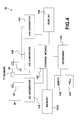
- FIG. 4 schematically represents the preferred connections of the electrical components. It illustrates the two coils (30,32) having a side-by-side configuration, which means that they are on a same side but are spaced-apart from each other.
- One coil is an emitter coil (30) and the other is a receiver coil (32).
- Each coil (30,32) comprises a wire wound around itself numerous times, preferably around the edge of a respective core element (34,36). The wire winding is made along the length of the core elements (34,36).
- These core elements (34,36) are preferably in the form of plates, but other forms or shapes are also possible. They could also be slightly concave or convex instead of being flat plates.
- the core elements (34,36) are made of a material having a high magnetic permeability and which can transmit the magnetic flux towards the interior of the launder (12) where the measurements are taken. Such material should have a B/H value, representing the magnetic permeability, between 10 000 and 1 000 000. It also has to resist the temperatures reached inside the probe (20).
- An example of a suitable material is the one known as MuMetalTM or Hy Mu 80TM, and which typically contains nickel (80%), iron (15%), Molybdenum (4,2%), Manganese (0,5%) and carbon (0,02%). Heat-treating the alloy in dry hydrogen to increase the grain size enhances the magnetic properties of the material. Other materials can be used as well, such as the ones known as Magnifier 7904TM, PermalloyTM, HypernomTM, etc.
- the core elements (34,36) are disposed such as to have their longitudinal axis being somewhat perpendicular to the flow direction of liquid metal.
- each of the core elements (34,36) can be set at an angle which varies from about 30 degrees on both sides of a perpendicular position.
- the emitter coil (30) is used to generate an alternating magnetic flux.
- Both coils (30,32) are arranged and disposed in a way that the alternating magnetic flux from the emitter coil (30) induces a voltage signal in the receiver coil (32). They are also held in close proximity of the location of liquid metal.
- the coils (30,32) are held close against the side of the refractory material (18). The magnetic flux is carried through the refractory material (18) and then across the path of liquid metal. There is thus no direct contact between the coils (30,32) and the liquid metal, the system (10) working completely in a remote manner.
- the receiver coil (32) continuously receives a signal from the emitter coil (30) even if the launder (12) is empty. However, the overall signal through the receiver coil (32) increases in presence of liquid metal. This changes the signal measured in the receiver coil (32) and ultimately allows the system (10) to determine the level of liquid metal upon analysis of the variation of the signal measured in the receiver coil (32).
- the present invention can be used with a very wide range of metals, including and not limited to aluminum, brass, copper, iron, lead, magnesium, steel, titanium, zinc and many others, or their alloys.
- the system (10) is primarily intended for use with liquid metals, it can also be used with melted salts that are electric conductors.
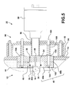
- FIG. 5 there is shown a cross-sectional view taken from the top of the launder (12) illustrated in FIG.1. It shows the sensor assembly, which is located inside the probe (20).
- the sensor assembly comprises a two-part hollow receptacle (40), which is designed to hold and protect the two coils (30,32).
- Both parts (40a,40b) of the receptacle (40) are made of a ceramic material or any other suitable material having no or only a weak effect on an electromagnetic signal to be sent from the emitter coil (30) to the receiver coil (32).
- FIGS. 6 and 7 show the two parts (40a,40b) of the receptacle (40) being separated from each other.
- They are preferably made of a carbon-carbon composite, such as the one known under the trade name "K-Karb" from Kaiser Compositek. It has been found that this material has the required mechanical properties at high temperature and no adverse effect on the signal. It is further capable of withstanding the harsh environment of a cast house.
- Other materials such as alumina, silica, mullite, any continuation of alumina with silica or zirconia, are also suitable candidates for the construction of the receptacle (40).
- the receptacle (40) is provided with a hollow internal housing (40c).
- Slots (41) are provided in the second part (40b) to hold the corresponding core elements (34,36).
- the slot in the middle is used for an optional third core element (60), which is described later.
- the middle slot is provided with a hole (41a) to accommodate the wires that need to reach the housing (40c).
- a temperature sensor (42) within the housing (40c) in order to measure the temperature in the vicinity of the coils (30,32).
- the temperature sensor (42) preferably comprises either a thermocouple or a resistivity thermal device (RTD).
- RTD resistivity thermal device
- the selection between the two kinds of temperature sensors is essentially dependent upon the highest temperature reached in the housing (40c).
- a RTD is preferred when the temperature is about 400°C or less since it is less expensive than a thermocouple.
- the electrical wires have been omitted from FIG. 5 for clarity purposes.
- Each coil (30,32) has two electrical wires and the temperature sensor (42) has also two. A total of six electrical wires are coming out of the sensor assembly.
- the wire used in constructing the coils (30,32) has to be electrically insulated but the interior portion has to be a good electrical conductor. It further has to resist to high temperature oxidation. Hence, copper can not be used alone since it rapidly losses its electrical conductivity as it becomes oxidized due to in the environment and high temperatures in cast houses.
- a nickel-clad copper or aluminum wire can be used.
- the nickel-clad copper wire preferably has a diameter between 0,15 and 1,0 mm.
- a wire made of aluminum should have a purity of 99,5% or higher in order to be a good conductor.
- the aluminum wire preferably has a diameter between 0,25 and 1,5 mm in diameter, the most preferred diameter being between 0,5 and 0,8 mm.
- the electrical insulator covering the wire may be a glass or mica sheath.
- alumina obtained by anodization could be used.
- a very suitable form of anodized aluminum is the one commercially obtained from Alumat Inc. (Ponoma, California), which allows the wire to be shaped without breaking the layer of alumina. Other materials can be used as well.
- the wires used in the coils (30,32) have to be designed to withstand high temperatures. This could be achieved using a double-sheathed wire (50) made in accordance with another aspect of the present invention.
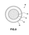
- FIG. 8 shows an example of a cross-section of this double-sheathed wire (50). It could be prepared in one step by a conventional cold drawing system.
- the double-sheathed wire (50) preferably comprises a copper or pure nickel core (52).
- the core (52) comprises a first seamless sheath (54) made of a high nickel-base content alloy or other malleable non-oxidizing alloys.
- the first sheath (54) is made of an InconelTM 600 alloy.
- the core (52) and the first sheath (54) are enclosed within a second sheath (56), preferably made of the same material as the first sheath (54). These components are coaxially disposed and are further provided with an annular space (58) between them.
- This space (58) is preferably packed with an electrically insulting and high temperature resistant material to prevent them from being in electrical contact.
- This material is preferably a ceramic powder, such as magnesium oxide (MgO). Other materials could be used as well.
- the double-sheathed wire (50) preferably has an outside diameter between 0,8 and 2,0 mm, most preferably between 1,0 and 1,5 mm.
- the inside diameter of the second sheath (56) is preferably between 0,4 and 1,6 mm, most preferably between 0,6 and 1,1 mm.
- the resistivity of a 1,0 mm outside diameter double-sheathed wire (50) with a nickel clad-copper core is about 1,7 milliohm per cm at room temperature. This increases to about 10 milliohms per cm at 1100°C. It has been found that this wire (50) can be used for several weeks in oxidizing atmospheres having a temperature up to 1100°C. It should be noted that the double-sheathed wire (50) could also be used in other high temperature applications.
- the length of the core elements (34,36) determines the height of liquid metal that can be measured.
- core elements (34,36) having 150 mm in length can measure between 1 and 150 mm of liquid metal.
- Core elements (34,36) typically can be made from 5 mm to 800 mm in length and have windings between 30 and 200 turns. The preferred number of turns is between 60 and 120, the most preferred being about 90.
- the thickness of the core elements (34,36) is also an important parameter. Thick coils produce a magnetic field that occupies a large volume. If the magnetic field is too wide, then it would go through the steel frame (14) of the launder (12). This is undesirable since the temperature of the frame (14) changes drastically during a cast, causing a signal drift. For example, during a normal cast of aluminum, the temperature of the frame (14) of the launder (12) increases from room temperature to 200°C.
- the first (34) and the second (36) core elements are allowing to solve this problem.
- a third core element (60) may be placed between the two coils (30,32).
- the third core element (60) is preferably made of the same material than that of the other core elements (34,36) or an equivalent. It contributes to further focussing the magnetic field through the center aperture (22), thereby reducing its interaction with the frame (14) of the launder (12). Spacers (49) are preferably used to maintain the spacing between all core elements (34,36,60).
- the third core element (60) is placed perpendicular to the coils axis. It is in the form of a sheet having between about 50 and 280 mm in length, between about 15 and 50 mm in height, and between about 0,1 and 5 mm in thickness. With the third core element (60), the distance between the two coils (30,32) is typically from 5 to 30 mm, depending on their length, compared to between 50 and 75 mm without a third core element. The third core element (60) also enables the system (10) to measure the effect of the inductance in the liquid metal at a distance of up to 100 mm away from the probe (20) into the launder (12).
- Concentrating the magnetic flux at the center of the aperture (22) decreases the distance between the coils (30,32) and reduces the portion of magnetic flux going through the frame (14) of the launder (12). The effect of the surrounding steel thus becomes negligible when the third core element (60) is placed between the two coils (30,32).
- the probe (20) needs to be held in place while it is used. It is necessary that the sensor assembly of the probe (20) be held so that the distance between the coils (30,32) and the liquid metal does not change. The contrary would cause a signal drift and thus give an incorrect indication of the liquid level.
- the probe (20) is above the launder (12)
- the fastening of the probe (20) requires some attention because the relative distance between the frame (14) and the center of the launder (12) changes with the thermal expansion.
- a novel fastening assembly (90) has been devised so as to allow the sensor portion of the probe (20), and thereby the coils (30,32), to be held at a constant distance from the outer side of the refractory material (18). This keeps the distance between the coils (30,32) and the liquid metal as constant as possible over the range of temperatures.
- the fastening assembly (90) preferably comprises a protective cover (92) that is made of a ceramic material or a carbon-carbon composite material. Other suitable materials can be used as well.
- the cover (92) is removably mounted around the aperture (22) made through the frame (14) of the launder (12).
- the fastening assembly (90) preferably comprises a fixation frame (94) welded around the aperture (22).
- This fixation frame (94), shown in FIG. 2 is preferably made of stainless steel 300 series and comprises fastening bolts (94a) projecting therefrom. Other materials can be used as well.
- the protective cover (92) is inserted over the fixation frame (94) and the bolts (94a) are inserted through corresponding holes in the cover (92).
- the free end of the bolts (94a) protrudes from the exterior of the cover (92) and nuts (94b) are used to lock the cover (92) in position.
- the central portion of the cover (92) is preferably provided with three holes.
- One is to accommodate a tube (96) through which the electrical wires will run.
- FIGS. 1 to 3 and 5 show that the tube (96) ends with an enlarged adapter (98) in which the terminals of the electrical wires of the probe (20) are connected to corresponding external wires.
- the other side holes (101) are receiving corresponding bolts (100).
- the tube (96) and the bolts (100) are free to slide in their respective hole.
- These bolts (100) are preferably made of stainless steel but made be made of other suitable alloys.
- One end of the bolts (100) is threaded and is located in corresponding chamfers (102) made on the face of the receptacle (40) in engagement with the refractory material (18). Nuts (104) are provided on these ends.
- the bolts (100) are also rigidly connected to a plate (106) located at the back of the other part of the receptacle (40). This rigid connection is achieved, for instance, by welding the bolts (100) to the plate (106).
- the plate (106) is preferably made of stainless steel.
- a compression spring (108) is coaxially mounted around each bolt (100), between the interior wall of the cover (92) and a washer (110) resting against the plate (106) at the back of the receptacle (40).
- the bolts (100) act as guide rods to keep the probe (20) in registry with the aperture (22) as the launder expands or contracts.
- the compression springs (108) provide a force which is constantly applied on the receptacle (40) to keep it in engagement against the side wall of the refractory material (18) even when the frame (14) and refractory material (18) expand at different rates.
- the cover (92) should be designed to contain spillage of liquid metal in the event that the refractory material (18) breaks in the region of the aperture (22).
- the emitter coil (30) receives a signal from an AC generator (120) in the form of a constant AC current.
- the AC generator (120) is controlled by a control module (122), consisting for example of a computer.
- the control module (122) is used to control the operation of the system (10) and calculate the change in inductance into a value that is proportional to the level of liquid metal in the launder (12).
- the signal sent to emitter coil (30) is preferably in the form of a sinusoidal wave having a frequency between 0,1 and 10 kHz.
- the preferred frequency is 1 kHz with a current of 500 mA.
- control module (122) measures the inductance in the receiver coil (32) and the temperature in the housing (40c) of the receptacle (40).
- the receiver coil (32) and the temperature sensor (42) are connected to corresponding analog-to-digital converters (124,126), themselves connected to the control module (122).
- the system (10) is preferably calibrated in two steps.
- the probe (20) is calibrated by heating it in the controlled environment of a furnace.
- the signal values are recorded from room temperature to 400°C, for instance.
- FIG. 9 shows a typical relationship between the signal and temperature of a 150 mm probe.
- a second order equation of the relationship between signal and temperature is calculated from the results and is downloaded in the non-volatile memory (122a) of the control module (122).
- the user enters the lower and higher signal that will be measured by the system (10). It is done for instance by pressing an "Empty" button (130) on a keyboard (132) when the launder (12) is empty. At this time, the lower signal value and the temperature are recorded in the non-volatile memory (122a). The user then places a plate (not shown), which is larger that the core length, in the launder (12).
- the plate preferably has a thickness of at least 4 mm and is made of the same metal or alloy to be transferred, for example a plate of aluminum if aluminum is used.
- FIG. 10 shows a typical relationship between the aluminum level and the relative signal of a 150 mm probe. The relationship is preferably described by a third order equation. This equation is downloaded in the non-volatile memory (122a) to be used during the calculations.
- the system (10) In use, the system (10) generates and measures the inductance and makes corrections for the change in temperature of the probe (20). It reads the probe signal and the temperature. The control module (122) compares the temperature with the temperature used in calibration. The signal values are then corrected according to the temperature equation. After temperature correction, the system (10) calculates the level using, for instance, the third order equation and the lower and higher values recorded by the user. The level is finally displayed or recorded in a display device (138). Furthermore, preset values can be provided to trigger alarm signals whenever the level reaches these values.
- a probe with a span of 150 mm was fixed on the side of the wall of a launder.
- Two equations have been downloaded into the non-volatile memory of the control module.
- ⁇ S was equal 51 arbitrary units.
- the processor had to determine whether the operation temperature was higher or lower than the calibration temperature. If the operation temperature was higher than the calibration temperature, then the equation (4) had to be used. If the operation temperature was lower than calibration temperature, then the equation (5) had to be used. In the case, equation (4) was used, giving a value for V (corr) of 21 500 arbitrary units. This value was then used for measuring the metal level.
- V (corr) V measured - ⁇ S, for T calibration ⁇ T operation
- V (corr) V measured + ⁇ S, for T calibration > T operation
- the metal level was calculated using this value in equation (2). That gave a value of 126 mm.
- the system The sensitivity and precision of a system (hereinafter "the system") constructed in accordance with the present invention were compared with that of a commercially available device which was based on the measurement of capacitance.
- the probe of the system was similar to that used in example of calibration, that is with a span of 150 mm. It featured an emitter coil and a receiver coil of 90 windings operating at the frequency of 1 kHz and with a current of about 500 mA.
- the probe was calibrated by the procedure described earlier. It was installed in the side of a launder through which was flowing an AA 5000 series aluminum alloy. The temperature of the metal was 750°C, and the temperature of the frame of the launder was about 150°C.
- the commercially available capacitance probe was also installed in the side of the launder, about 30 cm away from the probe of the system. Then, the performance of the two probes was recorded on a same strip chart recorder over a period of about 60 minutes. The resulting graphs are shown in FIG. 11, where they are set in superposed manner for comparison.
- the graph A relates to the prior art device, while graph B relates to the novel system.
- the signal to noise ratio of the system (B) is much better than that of the other device (A). This is clearly visible from the fact that the amplitude of the oscillations of the recorder trace in graph A are about four times wider than that those of graph B.
Landscapes
- Physics & Mathematics (AREA)
- Engineering & Computer Science (AREA)
- Electromagnetism (AREA)
- Power Engineering (AREA)
- Thermal Sciences (AREA)
- Fluid Mechanics (AREA)
- General Physics & Mathematics (AREA)
- Measurement Of Levels Of Liquids Or Fluent Solid Materials (AREA)
Applications Claiming Priority (4)
| Application Number | Priority Date | Filing Date | Title |
|---|---|---|---|
| US776275 | 2001-02-02 | ||
| CA002334063A CA2334063A1 (en) | 2001-02-02 | 2001-02-02 | System and method for measuring liquid metal levels or the like |
| CA2334063 | 2001-02-02 | ||
| US09/776,275 US6577118B2 (en) | 2001-02-02 | 2001-02-02 | System and method for measuring liquid metal levels or the like |
Publications (2)
| Publication Number | Publication Date |
|---|---|
| EP1229313A2 true EP1229313A2 (de) | 2002-08-07 |
| EP1229313A3 EP1229313A3 (de) | 2003-09-03 |
Family
ID=25682374
Family Applications (1)
| Application Number | Title | Priority Date | Filing Date |
|---|---|---|---|
| EP02002378A Withdrawn EP1229313A3 (de) | 2001-02-02 | 2002-01-31 | Vorrichtung und Verfahren zur Messung des Füllstandes von Flüssigmetall |
Country Status (1)
| Country | Link |
|---|---|
| EP (1) | EP1229313A3 (de) |
Cited By (2)
| Publication number | Priority date | Publication date | Assignee | Title |
|---|---|---|---|---|
| US20130147465A1 (en) * | 2010-08-09 | 2013-06-13 | Danieli Automation Spa | Device to detect the level of liquid metal in a casting apparatus and relative method |
| WO2024027542A1 (zh) * | 2022-08-01 | 2024-02-08 | 中广核研究院有限公司 | 互感式液态金属泄漏监测装置及其应用 |
Family Cites Families (5)
| Publication number | Priority date | Publication date | Assignee | Title |
|---|---|---|---|---|
| CH624323A5 (de) * | 1977-09-19 | 1981-07-31 | Atomenergi Ab | |
| LU83969A1 (de) * | 1982-02-23 | 1983-09-02 | Arbed | Verfahren zum messen des fuellstandes von fluessigen metallen in stranggiessanlagen |
| SE451507B (sv) * | 1982-12-06 | 1987-10-12 | Studsvik Energiteknik Ab | Forfarande och anordning for metning av kvarvarande mengd smelt metall pa bottnen eller dylikt av en behallare i samband med urtappning av smelt metall ur behallaren |
| DE3427563C2 (de) * | 1984-07-26 | 1986-12-11 | Stopinc Ag, Baar | Einrichtung zur elektromagnetischen Füllstandsmessung für metallurgische Gefässe |
| IT1222337B (it) * | 1987-10-21 | 1990-09-05 | Ceda Costruzioni Elettromeccan | Dispositivo per la misura del livello di metallo liquido in un cristallizzatore per lingottiera per colata continua |
-
2002
- 2002-01-31 EP EP02002378A patent/EP1229313A3/de not_active Withdrawn
Cited By (3)
| Publication number | Priority date | Publication date | Assignee | Title |
|---|---|---|---|---|
| US20130147465A1 (en) * | 2010-08-09 | 2013-06-13 | Danieli Automation Spa | Device to detect the level of liquid metal in a casting apparatus and relative method |
| US9404786B2 (en) * | 2010-08-09 | 2016-08-02 | Danieli Automation Spa | Device to detect the level of liquid metal in a casting apparatus and relative method |
| WO2024027542A1 (zh) * | 2022-08-01 | 2024-02-08 | 中广核研究院有限公司 | 互感式液态金属泄漏监测装置及其应用 |
Also Published As
| Publication number | Publication date |
|---|---|
| EP1229313A3 (de) | 2003-09-03 |
Similar Documents
| Publication | Publication Date | Title |
|---|---|---|
| US3797310A (en) | Temperature sensing device | |
| US4377550A (en) | High temperature liquid level sensor | |
| US4643586A (en) | Equipment and method for calibration of instruments having a temperature sensing unit | |
| US3962919A (en) | Temperature compensated inductive liquid metal level detection system | |
| GB1585496A (en) | Coil arrangement for electro-magnetic measurements | |
| US20120048011A1 (en) | Sensor and method for measuring the surface level of a liquid phase metal | |
| US6577118B2 (en) | System and method for measuring liquid metal levels or the like | |
| US3956936A (en) | Temperature-measuring system | |
| US3580078A (en) | Thermocouple failure indicating device | |
| Roeser | Thermoelectric thermometry | |
| JP3418407B2 (ja) | プリント配線板の測温型外部接続機構 | |
| US8152978B2 (en) | Apparatus and method for measuring hydrogen concentration in molten metals | |
| CA2334063A1 (en) | System and method for measuring liquid metal levels or the like | |
| WO2000054027A1 (en) | Probe device for apparatus for monitoring corrosion of a material | |
| US3115781A (en) | Apparatus for measuring furnace temperature | |
| US5104234A (en) | Air cooled thermocouple lance | |
| JP3118621B2 (ja) | 測温機能付きカプセル型ひずみゲージ | |
| JP2849457B2 (ja) | 熱分析装置の試料温度検出装置 | |
| KR100563248B1 (ko) | 상온보상용 소선 및 순금속 열전대 | |
| JPH0572050A (ja) | 熱電対測温計の精度管理方法 | |
| Bedford | Reference tables for platinum 20% Rhodium/Platinum 5% Rhodium thermocouples | |
| JPS61104234A (ja) | 温度測定用素子 | |
| GB2312285A (en) | solid electrolyte sensor for oxygen in molten substance | |
| US4250751A (en) | Head for an electronic thermometer | |
| SU415894A3 (de) |
Legal Events
| Date | Code | Title | Description |
|---|---|---|---|
| PUAI | Public reference made under article 153(3) epc to a published international application that has entered the european phase |
Free format text: ORIGINAL CODE: 0009012 |
|
| AK | Designated contracting states |
Kind code of ref document: A2 Designated state(s): AT BE CH CY DE DK ES FI FR GB GR IE IT LI LU MC NL PT SE TR |
|
| AX | Request for extension of the european patent |
Free format text: AL;LT;LV;MK;RO;SI |
|
| PUAL | Search report despatched |
Free format text: ORIGINAL CODE: 0009013 |
|
| AK | Designated contracting states |
Kind code of ref document: A3 Designated state(s): AT BE CH CY DE DK ES FI FR GB GR IE IT LI LU MC NL PT SE TR |
|
| AX | Request for extension of the european patent |
Extension state: AL LT LV MK RO SI |
|
| 17P | Request for examination filed |
Effective date: 20040223 |
|
| AKX | Designation fees paid |
Designated state(s): AT BE CH CY DE DK ES FI FR GB GR IE IT LI LU MC NL PT SE TR |
|
| 17Q | First examination report despatched |
Effective date: 20060919 |
|
| STAA | Information on the status of an ep patent application or granted ep patent |
Free format text: STATUS: THE APPLICATION IS DEEMED TO BE WITHDRAWN |
|
| 18D | Application deemed to be withdrawn |
Effective date: 20070130 |