EP1229529A2 - Verfahren zur Erzeugung von dauerhaften bedruckten CDs mit einer klaren Heissprägebeschichtung - Google Patents
Verfahren zur Erzeugung von dauerhaften bedruckten CDs mit einer klaren Heissprägebeschichtung Download PDFInfo
- Publication number
- EP1229529A2 EP1229529A2 EP02250376A EP02250376A EP1229529A2 EP 1229529 A2 EP1229529 A2 EP 1229529A2 EP 02250376 A EP02250376 A EP 02250376A EP 02250376 A EP02250376 A EP 02250376A EP 1229529 A2 EP1229529 A2 EP 1229529A2
- Authority
- EP
- European Patent Office
- Prior art keywords
- section
- transfer side
- donor web
- layer
- digitally readable
- Prior art date
- Legal status (The legal status is an assumption and is not a legal conclusion. Google has not performed a legal analysis and makes no representation as to the accuracy of the status listed.)
- Withdrawn
Links
Images

Classifications
-
- G—PHYSICS
- G11—INFORMATION STORAGE
- G11B—INFORMATION STORAGE BASED ON RELATIVE MOVEMENT BETWEEN RECORD CARRIER AND TRANSDUCER
- G11B23/00—Record carriers not specific to the method of recording or reproducing; Accessories, e.g. containers, specially adapted for co-operation with the recording or reproducing apparatus ; Intermediate mediums; Apparatus or processes specially adapted for their manufacture
- G11B23/38—Visual features other than those contained in record tracks or represented by sprocket holes the visual signals being auxiliary signals
- G11B23/40—Identifying or analogous means applied to or incorporated in the record carrier and not intended for visual display simultaneously with the playing-back of the record carrier, e.g. label, leader, photograph
-
- B—PERFORMING OPERATIONS; TRANSPORTING
- B41—PRINTING; LINING MACHINES; TYPEWRITERS; STAMPS
- B41M—PRINTING, DUPLICATING, MARKING, OR COPYING PROCESSES; COLOUR PRINTING
- B41M7/00—After-treatment of prints, e.g. heating, irradiating, setting of the ink, protection of the printed stock
- B41M7/0027—After-treatment of prints, e.g. heating, irradiating, setting of the ink, protection of the printed stock using protective coatings or layers by lamination or by fusion of the coatings or layers
-
- G—PHYSICS
- G11—INFORMATION STORAGE
- G11B—INFORMATION STORAGE BASED ON RELATIVE MOVEMENT BETWEEN RECORD CARRIER AND TRANSDUCER
- G11B7/00—Recording or reproducing by optical means, e.g. recording using a thermal beam of optical radiation by modifying optical properties or the physical structure, reproducing using an optical beam at lower power by sensing optical properties; Record carriers therefor
- G11B7/24—Record carriers characterised by shape, structure or physical properties, or by the selection of the material
- G11B7/26—Apparatus or processes specially adapted for the manufacture of record carriers
-
- Y—GENERAL TAGGING OF NEW TECHNOLOGICAL DEVELOPMENTS; GENERAL TAGGING OF CROSS-SECTIONAL TECHNOLOGIES SPANNING OVER SEVERAL SECTIONS OF THE IPC; TECHNICAL SUBJECTS COVERED BY FORMER USPC CROSS-REFERENCE ART COLLECTIONS [XRACs] AND DIGESTS
- Y10—TECHNICAL SUBJECTS COVERED BY FORMER USPC
- Y10T—TECHNICAL SUBJECTS COVERED BY FORMER US CLASSIFICATION
- Y10T428/00—Stock material or miscellaneous articles
- Y10T428/31504—Composite [nonstructural laminate]
- Y10T428/3154—Of fluorinated addition polymer from unsaturated monomers
Definitions
- Label images on digitally readable discs can be printed using water-based inks. Further, production of digitally readable discs is increasingly custom or short run requiring digital printing methods such as thermal or piezoelectric injet to economically produce labels. Protecting these digitally readable disc label images against abrasion, water, alcohol, other liquid spills, ink smear, fading, blocking or other image-degradation processes and effects has become an important consideration. Such protection is particularly desirable for digitally readable disc label images produced with water-based (water-soluble) or other liquid inks, as well as documents printed or imaged with toner. These are commonly used in ink-jet printing, offset printing, electrophotography and the like.
- Hot and cold laminates are the most common methods used to protect images. However, laminates tend to be expensive, typically costing 6 to 80 cents per square foot for materials. The labor-intensive nature of producing durable prints via lamination also increases the cost of such prints. Laminates may be applied on one or both surfaces of the print. One-sided lamination may lead to excessive curling of the final print, whereas two-sided application can be very expensive in terms of material and labor costs and may excessively increase the thickness of the final print. Adhesives used for cold laminates may be tacky at room temperature, leaving a sticky residue at the edges of the discs. Additionally, binders used in creating cold laminates are typically water-based, which means the disc may delaminate if exposed to excessive water or other liquid.
- Liquid overcoats are also commonly used to protect photographic prints and are becoming more popular as protective coatings for inkjet images.
- Typical systems for applying these overcoats rely on roller coating or gravure type systems to dispense, gauge, and apply the coating.
- Smaller systems typically apply the overcoat off-line, rather than being an integral part of a single printing and coating unit.
- Larger systems used by the printing industry are in-line, but require extensive monitoring. Both systems require significant manual cleaning or intervention to maintain the components that contact the liquid.
- liquid overcoats tend to be slightly less expensive than laminates (6-18 cents per square foot). However, because currently available systems must be cleaned frequently and regularly monitored, these methods of using liquid overcoats are just as labor-intensive as the lamination methods, if not more labor-intensive. Additionally, many of the overcoat formulations have residual odors before and/or after application, and some people find these odors offensive or even harmful.
- UV light curable liquid overcoats are also available, such as the overcoats commonly used to protect magazine covers.
- the liquid is first applied to the surface of the print and then cured to yield a solid, durable, protective coating. Because these liquids are widely used in large volumes for the magazine industry, their cost tends to be significantly lower than most other overcoat options.
- the systems used to apply such UV-curable overcoats tend to be more complicated and costly than other liquid overcoat systems, due to the multi-step application and cure process.
- many of the overcoat formulations have strong odors, some of which are harmful or offensive to people.
- Malhotra (U.S. Patent No. 5,612,777 assigned to Xerox), Tutt & Tunney (U.S. Patent No. 5,847,738 assigned to Eastman Kodak Co.) and Tyagi et al. (U.S. Patent No. 5,783,348 assigned to Eastman Kodak Co.) disclose methods of applying a clear, scratch-resistant, lightfast, toner coating onto images.
- Malhotra describes photocopied color images created by first, depositing color toner images on a charge retentive surface; second, depositing a clear polymer toner material onto the charge retentive surface; and third, transferring and fusing the color toner images and clear polymer toner material onto a substrate.
- Tutt & Tunney describe a process of depositing and fusing a clear polymer toner on inkjet images.
- Tyagi et al. describes a similar process for coating clear toner over silver halide images.
- Powder coating methods are also commonly used in the commercial painting industry to powder coat products, parts, or assemblies.
- One powder coating method charges a powdered paint using an air gun outfitted with an electrode before spraying the charged paint onto an electrically grounded object.
- an electrically grounded object may be immersed in a charged, fluidized bed of paint particles (typically referred to as "fluidized bed powder coating").
- Another Malhotra patent (U.S. Patent No. 5,906,905 assigned to Xerox) discloses a method of creating photographic quality prints using imaging such as xerography or ink jet by, first, reverse reading toner images on a transparent substrate and then adhering the transparent substrate to a coated backing sheet, coated with a polymeric lightfastness material.
- thermal film material on a thermally printed substrate is also disclosed.
- Nagashima U.S. Patent No. 4,738,555 assigned to Toshiba discloses the use of a thermal print bar to thermally transfer a transparent protective layer of wax, vinyl chloride, vinyl acetate, acrylic resin, styrene or epoxy onto the thermally printed medium substrate.
- Tang et al. U.S. Patent No. 5,555,011 assigned to Eastman Kodak discloses a means to ensure that a thermal film that is being applied to a thermally printed surface has a clean break at the edge of the transfer. It describes a thermal film transfer method having a transport system which moves a dye-donor web and a receiver medium (i) in a forward direction along their respective paths past a thermal head, so that heat from the thermal head causes an area of the thermal film material coating between leading and trailing edges to transfer from the dye-donor web to the receiver medium and (ii) in a reverse direction along their respective paths such that the area of the thermal film material which is transferred to the receiver medium breaks cleanly at the trailing edge from a non-transferred area of the thermal film material that remains on the dye-donor web as the web support separates from the medium.
- Abe et al. discloses a method for protecting and covering a printed material on a substrate with a pressure-sensitive transferring protective covering material with at least (a) a first flexible substrate, (b) an adhesive layer, (c) a solid resin layer, and (d) a second flexible substrate, stacked in this order.
- the packaging, printing, and decorating industry uses colored ribbons, known as thermal transfer foils, hot stamping foils, roll foils, and transfer printing foils, for marking or decorating.
- This market uses solid fill colored ribbons or uniquely patterned ribbons to emboss lettering, patterns, barcodes, or insignias on wood, paper, leather, plastic, fabric, or metal parts. Examples include holograms on credit cards, metalized insignias on baseball cards, corporate logos on business cards, or colored or metalized designs on greeting cards.
- the hot stamp foiling process involves the transfer of the coatings from a carrier ribbon onto a substrate via a combination of heat and pressure.
- the present invention relates to a method of applying a protective overcoat to a surface of a digitally readable disc to create a digitally readable disc with a protective overcoat, comprising: applying heat and pressure to a donor web having a carrier side comprising carrier ribbon material and a transfer side comprising protective overcoat material, wherein the heat and pressure facilitate release of a section of the transfer side from adhering to the carrier side of the donor web and facilitate transfer of the section of the transfer side to adhering to the surface of the digitally readable disc.
- the present invention also relates to an overcoat for a digitally readable disc and the digitally readable disc itself to which the overcoat is applied, the overcoat on the digitally readable disc being made by the above-described method.
- the present invention also relates to a donor web providing a protective overcoat to a digitally readable disc, the donor web having:
- the present invention also relates to an apparatus comprising a donor web having a carrier side comprising carrier ribbon material and a transfer side comprising protective overcoat material, and a means of applying a protective overcoat to at least one surface of a digitally readable disc, by applying heat and pressure to the donor web, wherein the heat and pressure facilitate release of a section of the transfer side from adhering to the carrier side of the donor web and facilitate transfer of the section of the transfer side to adhering to the at least one surface of the digitally readable disc.
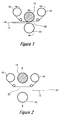
- FIG. 1 is a schematic view of a preferred embodiment of the apparatus of the present invention during application of a protective overcoat onto the digitally readable disc (12), showing a digitally readable disc (12), a heat roll (14), a pressure roll (22), a foil source roll (16) a carrier take-up roll (18), and a tensioned section of the donor web (20), the tensioned section being heated and pressed between the heat roll (14) and the pressure roll (22) onto the digitally readable disc (12).
- FIG. 2 is a schematic view of the apparatus of FIG. 1 after application of a protective overcoat onto the digitally readable disc (12) with the heat roll (14) and the pressure roll (22) positioned away from the tensioned section of the donor web (18) and the digitally readable disc (12) having already passed the tensioned section of the donor web (18).
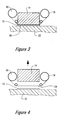
- FIG. 3 is a schematic view of another preferred embodiment of the apparatus of the present invention during application of a protective overcoat onto the digitally readable disc (12), showing a digitally readable disc (12), a heat die (14), a base (22), a foil source roll (16) a carrier take-up roll (18), and a tensioned section of the donor web (20), the tensioned section being heated and pressed between the heat die (14) and the base (22) onto the digitally readable disc (12).
- FIG. 4 is a schematic view of the apparatus of FIG. 2 after application of a protective overcoat onto the digitally readable disc (12) with the heat die (14) positioned away from the tensioned section of the donor web (18) and the digitally readable disc (12) having already passed the tensioned section of the donor web (18).
- FIG. 5 is a schematic view of several digitally readable disc layout options in the present invention: (a) printing onto the disc, coating the disc, recording onto the disc; (b) recording onto the disc, printing onto the disc, overcoating the disc; (c) printing onto the disc, overcoating the disc; (d) overcoating the disc
- the present invention provides a means of creating inexpensive, durable overcoatings for the label bearing side of a digitally readable disk that can compete or improve upon the quality and durability of currently-used printing and/or imaging methods.
- the label images can be produced, in a non-limiting embodiment, by digital printing devices such as inkjet printers generally using water-based inks.
- This invention uses a thermally-transferred, transparent overcoat material, which is applied as a clear transparent film, to protect the image printed on the digitally readable disk.
- the overcoats and media of the present invention are obtained by transferring thermal transfer material from a donor web which has a top side of carrier ribbon material, the carrier ribbon material anchoring the bottom side which has at least one layer of thermal transfer material. As the donor web is heated and pressed into contact with the printable surface of a digitally printable disc, the thermal transfer material is transferred onto the printable surface.
- the printing processes of the present invention can include, but are not limited to inks conventionally used in inkjet, offset, and gravure.
- it includes the imaging means used in liquid electrophotography, electrophotography, and conventional photography.
- inkjet printing for example, both dye based and pigment based inkjet inks can be used, but the invention is not limited to such inks.
- the clear thermal transfer overcoat film of the present invention improves image quality and increases durability of the images.
- the overcoat film provides good protection against various substances that might spill, either in the form of liquid or dry spills, on the surface of a print.
- substances which the present invention would protect against would be water, alcohol, ink, coffee, soda, ammonia based or other cleaning liquids, food stains (e.g. mustard, chocolate, berry), and dirt.
- the clear, thermal transfer overcoat film can be applied in a way that provides, for example, a gloss finish or a matte finish. This may be achieved through the control of the application temperature, pressure, and speed. In addition, the creation of patterns using a thermal bar as the heating element can be used to create unique matte or patterned finishes.
- the composition of the overcoat film can also be formulated to target specific properties. It can be formulated to achieve a specific gloss or matte level, and to enhance the gloss uniformity or the matte uniformity.
- the thermal transfer material can also be formulated with materials or additives which improve the printed image, specifically, indoor light fade resistance, UV light fade resistance, resistance to water and other liquids, vapor resistance, scratch resistance and blocking resistance.
- the thermal transfer material composition can also be formulated to have a colorless or color-tinted appearance, provide a flexible, conformable coating, decrease the required dry time, optimize the adhesion of the thermal transfer film to the digitally readable disc, optimize the release of the thermal transfer overcoat from the donor web, and minimize the adhesion of the thermal transfer overcoat to the base.
- the carrier ribbon material and the thermal transfer material there can also be layers that enhance the transfer of the thermal transfer material to the printable surface of the digitally readable disc.
- These additional layers can include, for example, an adhesive layer positioned as the exterior layer of the thermal transfer material. The primary function of this adhesive layer is to enhance the fixation of the thermal transfer material onto the printable surface of the digitally readable disc.
- Another example is a release layer positioned on the interior surface of the thermal transfer material next to the interior surface of the carrier ribbon material.
- the adhesive layer and the release layer can also include additives which enhance indoor and UV lightfade resistance, resistance to water and other liquids, vapor resistance, scratch resistance and blocking resistance in the printed images on the printable surface.
- the thermal transfer materials should be flexible. Materials should be selected such that the final film conforms to the surface of the digitally readable disc. During application, the material should not crack or break, thereby leaving blemishes, image degradations, or exposed medium.
- Non-limiting examples of light resisting additives that can be added to the thermal transfer material to be transferred to the printable surface of the digitally readable disc in the form of a clear overcoating are the hindered amine series light stabilizers.
- the hindered amine series light stabilizer can include commercially available hindered amine series light stabilizers having a property of dispersing within a region which it can react with a dye molecule and deactivate an active species.
- Preferable specific examples of such hindered amine series light stabilizers include TINUVIN 292, TINUVIN 123, and TINUVIN 144 (trademarks, produced by Japan Ciba-Geigy Company).
- the thermal materials can also include UV absorbers, which can include, but are not limited to, the benzophenone series UV absorbers, benzotriazole series UV absorbers, acetanilide series UV absorbers, cyanoacrylate series UV absorbers, and triazine series UV absorbers.
- UV absorbers can include, but are not limited to, the benzophenone series UV absorbers, benzotriazole series UV absorbers, acetanilide series UV absorbers, cyanoacrylate series UV absorbers, and triazine series UV absorbers.
- acetanilide series UV absorbers such as Sanduvor UVS powder and Sanduvor 3206 Liquid (trademark names, produced by Sando Kabushiki Kaisha); and commercially available benzotriazole series UV absorbers such as TINUVIN 328, TINUVIN 900, TINUVIN 1130, and TINUVIN 384 (trademark names, produced by Japan Ciba-Geigy Company), and Sanduvor 3041 Dispersion (trademark name, produced by Sando Kabushiki Kaisha).
- Non-limiting examples of liquid resistance additives or vapor resistance additives which can be added to the thermal transfer material layers, to be transferred to the printable surface of the digitally readable disc in the form of a clear overcoating are additives that decrease the wetability of the surface by decreasing the surface energy, thereby repelling liquids such as (but not limited to) water from the surface.
- These additives may include the family of fluoro-surfactants, silanes, siloxanes, organosiloxanes, siliconizing agents, and waxes or combinations thereof.
- the formulation of the layers can provide improvements.
- Individual thin layers may develop pits or pin holes in their surface during their coating to the carrier. These holes provide avenues for liquid or vapor to travel down to the printed surface.
- the probability of a pinhole extending all the way through the entire layer stack is decreased.
- this allows the individual layers to be optimized for a unique performance attribute, whereas it may not be possible to acquire as large a range of attributes from a single layer.
- an upper layer may be optimized for gloss, and it may cover a lower layer optimized for light fade resistance.
- the combination of the two may be the same thickness as a single layer that has lower gloss and inferior light fade and liquid resistant properties due to the tradeoffs associated with formulating that single layer.
- the present invention makes possible very thin individual layers on a digitally readable disc that can be applied either as transparent or opaque layers.
- thin protective layers as both undercoating and overcoating to a digitally readable disc, achieving durability and protection of print qualities without sacrificing good optical or media qualities in the finished product.
- One of the layers in the coating may consist of material having barrier properties (i.e., having very low permeability toward gases (e.g., oxygen or water vapor)).
- barrier properties i.e., having very low permeability toward gases (e.g., oxygen or water vapor)
- examples of the most widely used materials with barrier properties are co-polymers of acrylonitrile or co-polymers of vinylidene chloride or vinylidene fluoride.
- Use of materials with barrier properties in the overcoat makes it possible to dramatically increase protection of the overcoated print from humidity and fade (partially caused by oxidation of the colorants.
- the digitally readable disc may also include or be coated with materials which increase adhesion of inkjet dyes or pigments, increase adhesion of the overcoat material, optimize image quality, increase resistance to scratches, increase resistance to fading, increase resistance to moisture, or increase resistance to UV light.
- materials include, but are not limited to polyesters, polystyrenes, polystyrene-acrylic, polymethyl methacrylate, polyvinyl acetate, polyolefins, poly(vinylethylene-co-acetate), polyethylene-co-acrylics, amorphous polypropylene and copolymers and graft copolymers of polypropylene.
- the digitally readable disc material typically comprises a circular disc having both a printable surface and recordable surfaces , though the shape of the medium is not limited in any way and the size and thickness of the medium may vary.
- an image can be applied to a printable surface of the digitally readable disc using commonly known and available means, such as inkjet or electrostatic printing.
- An optional dryer can be used to ensure the ink is dry enough to facilitate coating adhesion before overcoating.
- the dryer can dry the wet image using convection, conduction or irradiation (for example, in a preferred embodiment, with any of the following: a radiative heating apparatus, a conductive heating apparatus, a convective blowing apparatus, an infrared apparatus, an infrared radiative heating element, an ultraviolet apparatus and a microwave apparatus).
- convection, conduction or irradiation for example, in a preferred embodiment, with any of the following: a radiative heating apparatus, a conductive heating apparatus, a convective blowing apparatus, an infrared apparatus, an infrared radiative heating element, an ultraviolet apparatus and a microwave apparatus.
- the image may also be preheated prior to coating, to facilitate the transfer of the overcoat material. If a dryer is used, the drying step may provide this preheating.
- the heating element used for transfer is selected from a group consisting of a heated roller, a ceramic heat bar, a heat die or a thermal printhead.
- a heated roller similar to what is used in most commercial laminators or many electrophotograpic printers, provides a good means of providing uniform, continuous, full width transfer of the overcoat.
- a ceramic heat bar similar to what is used in many monochrome electrophographic printers (a.k.a. instant-on fusers), also provides a good means of providing uniform, continuous, full width transfer of the overcoat.
- ceramic elements have a lower thermal mass than a typical heated roller, thus they quickly reach the desired transfer temperature and quickly cool following transfer, thereby enhancing energy efficiency and reducing start-up time.
- a thermal printhead or heat die similar to what is used in thermal transfer, dye sublimation printers or faxes, provides a good means of providing continuous or intermittent, full width or discrete, transfer of the overcoat.
- the heating element can be rigid, or it may be compressible, with the compression level influencing the nip area.
- the medium is positioned over a base, and the heating element and base are pressed towards each other to create a nip area.
- the base can be rigid, or it can be compressible, with the compression level influencing the nip area.
- the base may be coated with a non-stick (non-wetting), heat-resistant surface. A solid lubricant can be used to provide this surface.
- the solid lubricant may be a fluororesin, fluorocarbon, or fluoropolymer coating such as (poly)-tetrafluoroethylene (PTFE), perfluoroalkoxy (PFA), fluorinated ethylene propylene (FEP), ethylene tetrafluoroethylene (ETFE), ethylene chlorotrifluoroethylene (ECTFE), polyvinylidene fluoride (PVDF), with trade names such as Teflon, Silverstone, Fluoroshield Magna, Cerm-a-lon, Magna TR, Newcastleon, Apticote, or Edlon.
- a replenished liquid lubricant such as silicone oil, can be used to provide this non-stick surface.
- the heating element, the base (or pressure element) and the donor web span beyond the width of the printable surface of the digitally readable disc to be coated.
- the heating element and base maintain a constant nip force and area across the donor web, which is in contact with the digitally readable disc. Since the donor web and nip area extend beyond the print sides, full coating to all print edges is insured.
- the non-stick base surface ensures that the overcoat is only transferred to the printable surface and not to the surrounding non-stick surface of the base. Only that portion of the thermal transfer overcoat that touches the printable surface separates from the donor web. The rest, including the thermal transfer material overcoat portion extending beyond the edges, remains connected to the donor web.
- the present design also provides the added feature in that one source of overcoat can be used to coat any print size narrower than the source, without the need for post process trimming.
- the heating element When not being applied, the heating element may be removed from the donor web and base surfaces, thereby discontinuing transfer and allowing feed of the digitally readable disc under and away from the heater element. Also, application of the coating can be discontinued by reducing the temperature of the heating element or by reducing the nip force, which can be facilitated by raising the heating element or the combination of the heating element and donor web off the digitally readable disc surface
- the area of the printable surface that actually receives a transferred section of the thermal transfer overcoat can be further limited to a specific portion of the printable surface by limiting the section of the thermal transfer overcoat to the area in which heat and pressure is applied.
- This can be accomplished with the use of a thermal printhead, as used in thermal transfer printers.
- selected printed areas, such as colored images, on the printable surface can be overcoated while other printed areas, such as black and white text, can remain uncoated.
- Such an embodiment is shown in Fig. 3.
- Such selective overcoating of discrete areas on digitally printable discs is not feasible with traditional laminates and traditional laminating processes nor other digital coating processes.
- the speed of the donor web through the heating element is maintained at the same speed as the digitally readable disc, thus ensuring a uniform coverage.
- a source roll of donor web is located upstream of the heating element and a take-up roll is located downstream.
- the source roll is torque limited with a slip clutch or similar device to tension and present the thermal transfer material on the donor web, and to allow the unrolling of the donor web concurrent with the digitally readable disc during application but ensuring that uncontrolled unrolling does not occur.
- the take-up roll provides enough torque to peel the donor web from the coated disc's surface, but not enough to pull the donor web/ disc combination through the applicator or to distort the coating in the applicator. The take-up mechanism thus peels the donor web from the coated medium, collects the donor web, and helps maintain the uniform tension on the donor web during application.
- a thermal transfer overcoat module can be offered to use, for example, as a plug-in module for an apparatus that prints on the surface of digitally readable discs such as CD's.
- An inkjet printer in combination with a thermal transfer overcoat module would provide a compact reliable system for creating durable photo-quality prints.
- a printer can be built which completely incorporates the thermal transfer overcoating function into an integrated printing and coating printer.
- a stand-alone coater can be used, which allows the user to hand load the already printed digitally readable discs to be overcoated.
- Covering the image with a thermal transfer material overcoat offers the advantage of providing an intimate, gap-free bond with the digitally readable disc, thus protecting the image from the outside environment.
- Thermal transfer overcoating is an improvement over lamination as previously disclosed.
- a thermal transfer material overcoat is transferred onto the digitally readable disc surface only at the locations that are subjected to the contact pressure and heat. Thus, it disengages from the donor web as it transfers and only the thermal transfer material and not the donor web is attached to the disc surface. There is clean separation of the donor web and the disc material at all edges of the print.
- the transferred laminate is still attached to the overcoat supply source, until separated by a manual or automated trimming step. In the present invention, there is no need for a secondary manual or automated trimming step to disconnect the thermal overcoat supply source (the donor web) from the overcoated disc. This also facilitates the easy feeding of digitally readable discs.
- Prints embodied in the present invention can be produced by a variety of apparatuses. Such apparatuses typically comprise the elements illustrated in FIGS. 1 and 3, though it will be appreciated that other apparatuses may be employed without departing from the scope and true spirit of the present invention.
- the take up roll (18), or other similar means tensions a section (20) of the donor web coming from the source roll (16), and at least one heating element roll (14) heats the segment of the donor web and presses it against the medium positioned on a base (22) (which in this embodiment is in the form of a pressure roller) to transfer a segment of the thermal transfer material layer of the donor web onto the digitally readable disc (12) as it moves through the system.
- a base (22) which in this embodiment is in the form of a pressure roller
- the heating element (14) or other similar means is raised and the pressing element (22) is lowered so that they no longer provide heat and pressure to the donor web.
- the thermal transfer film layer separates from the donor web during transfer up to the edges of the digitally readable disc, with the thermal transfer material layer adhering to the surface of the disc where the pressure and heat were applied and continuing to be attached to the donor web beyond the edges of the disc.
- FIG. 2 shows the apparatus of FIG. 1 with the ribbon handler tensioning the donor web in a position away from and no longer abutting the heater and base as the digitally readable disc moves through the system. In this position, no thermal transfer material layer transfers onto the disc as it moves through the system, and no material is collected in the take-up roll.
- the take up roll (18), or other similar means tensions a section (20) of the donor web coming from the source roll (16), and at least one heating element die (14) heats the segment of the donor web and presses it against the medium positioned on a base (22) (which in this embodiment is in the form of a platen) to transfer a segment of the thermal transfer material layer of the donor web onto the digitally readable disc (12) as it moves through the system.
- a base (22) which in this embodiment is in the form of a platen
- the heating die (14) or other similar means is raised above the platen (22) so that the combination of the two no longer provides heat and pressure to the donor web.
- the thermal transfer film layer separates from the donor web during transfer up to the edges of the digitally readable disc, with the thermal transfer material layer adhering to the surface of the disc where the pressure and heat were applied and continuing to be attached to the donor web beyond the edges of the disc.
- FIG. 4 shows the apparatus of FIG. 3 with the ribbon handler tensioning the donor web in a position away from and no longer abutting the heating die and base as the digitally readable disc moves through the system In this position, no thermal transfer material layer transfers onto the disc as it moves through the system, and no material is collected in the take-up roll.
- FIG. 5 shows a schematic view of several digitally readable disc layout options in the present invention: (a) printing onto the disc, coating the disc, recording onto the disc; (b) recording onto the disc, printing onto the disc, overcoating the disc; (c) printing onto the disc, overcoating the disc; (d) overcoating the disc
Landscapes
- Decoration By Transfer Pictures (AREA)
- Application Of Or Painting With Fluid Materials (AREA)
- Ink Jet (AREA)
- Electronic Switches (AREA)
Applications Claiming Priority (2)
| Application Number | Priority Date | Filing Date | Title |
|---|---|---|---|
| US09/774,426 US20020101497A1 (en) | 2001-01-30 | 2001-01-30 | Method for creating durable printed CD's using clear hot stamp coating |
| US774426 | 2001-01-30 |
Publications (2)
| Publication Number | Publication Date |
|---|---|
| EP1229529A2 true EP1229529A2 (de) | 2002-08-07 |
| EP1229529A3 EP1229529A3 (de) | 2005-03-09 |
Family
ID=25101194
Family Applications (1)
| Application Number | Title | Priority Date | Filing Date |
|---|---|---|---|
| EP20020250376 Withdrawn EP1229529A3 (de) | 2001-01-30 | 2002-01-21 | Verfahren zur Erzeugung von dauerhaften bedruckten CDs mit einer klaren Heissprägebeschichtung |
Country Status (4)
| Country | Link |
|---|---|
| US (2) | US20020101497A1 (de) |
| EP (1) | EP1229529A3 (de) |
| JP (1) | JP2002358758A (de) |
| HK (1) | HK1045750A1 (de) |
Cited By (2)
| Publication number | Priority date | Publication date | Assignee | Title |
|---|---|---|---|---|
| WO2006069332A3 (en) * | 2004-12-22 | 2007-04-19 | Imation Corp | Optical media with laminated inkjet receptor |
| CN109446862A (zh) * | 2014-03-17 | 2019-03-08 | 爱克发有限公司 | 用于数字指纹代码的解码器和编码器 |
Families Citing this family (10)
| Publication number | Priority date | Publication date | Assignee | Title |
|---|---|---|---|---|
| JP4402964B2 (ja) * | 2004-01-14 | 2010-01-20 | 富士フイルム株式会社 | パターン膜形成方法 |
| US8252409B2 (en) * | 2004-02-19 | 2012-08-28 | Hewlett-Packard Development Company, L.P. | Durable printed composite materials and associated methods |
| US20060177634A1 (en) * | 2004-09-01 | 2006-08-10 | John Lazar | Activator means for pre-applied adhesives |
| US20070071945A1 (en) * | 2005-09-29 | 2007-03-29 | Schalk Wesley R | System and method for forming gloss and matte transparent labels from a common film and emulsion set |
| US20080092153A1 (en) * | 2006-10-11 | 2008-04-17 | Imation Corp. | System and process for forming a durable image on an optical disk |
| WO2010030932A2 (en) * | 2008-09-12 | 2010-03-18 | Brigham Young University | Optical data media containing an ultraviolet protection layer |
| US20130032288A1 (en) * | 2010-01-07 | 2013-02-07 | Hid Global Corporation | Transfer lamination |
| WO2014022088A1 (en) | 2012-07-31 | 2014-02-06 | Hid Global Corporation | Transfer lamination |
| WO2017025827A1 (en) | 2015-08-13 | 2017-02-16 | Assa Abloy Ab | Transfer lamination |
| EP3356144B1 (de) | 2015-10-02 | 2020-12-23 | Assa Abloy Ab | Laminiervorrichtung für kartengrundkörper und verfahren |
Family Cites Families (24)
| Publication number | Priority date | Publication date | Assignee | Title |
|---|---|---|---|---|
| JPS6151391A (ja) * | 1984-08-20 | 1986-03-13 | Toshiba Corp | 熱転写記録媒体と熱転写装置 |
| US4724026A (en) * | 1985-02-05 | 1988-02-09 | Omnicrom Systems Corporation | Process for selective transfer of metallic foils to xerographic images |
| JPS62216730A (ja) * | 1986-03-18 | 1987-09-24 | Gunze Ltd | 熱圧着ラミネ−ト方法及び装置 |
| DE3721651A1 (de) * | 1987-07-01 | 1989-01-12 | Philips & Du Pont Optical | Verfahren zum bedrucken plattenfoermiger informationstraeger |
| DE69032843T2 (de) * | 1989-07-14 | 1999-08-12 | Dai Nippon Insatsu K.K., Tokio/Tokyo | Thermische Übertragungsschicht |
| US5203941A (en) * | 1989-10-19 | 1993-04-20 | Avery Dennison Corporation | Process for manufacturing plastic siding panels with outdoor weatherable embossed surfaces |
| US5397634A (en) * | 1993-07-22 | 1995-03-14 | Rexham Graphics Incorporated | Transferable protective cover layers |
| US5555011A (en) * | 1994-01-26 | 1996-09-10 | Eastman Kodak Company | Lamination of a protective layer over an image produced by a thermal printer |
| US5512126A (en) * | 1994-03-11 | 1996-04-30 | Polaroid Corporation | Optical laminator |
| US5486397A (en) * | 1994-04-29 | 1996-01-23 | Polaroid Corporation | Protected reflection image |
| US5942330A (en) * | 1994-05-19 | 1999-08-24 | Bostik, Incorporated | Adhesive compositions and methods and articles of manufacture comprising same |
| JP3478647B2 (ja) * | 1994-12-09 | 2003-12-15 | キヤノン株式会社 | 感圧転写性保護被覆材料及びこれを用いた画像の保護被覆方法 |
| US5798161A (en) * | 1995-01-20 | 1998-08-25 | Dai Nippon Printing Co., Ltd. | Optical disk, method of forming image on optical disk, image forming apparatus and adhesive layer transfer sheet |
| JPH08310170A (ja) * | 1995-05-18 | 1996-11-26 | Dainippon Printing Co Ltd | ホログラム付き印画物及びその作成方法 |
| JP3776480B2 (ja) * | 1995-06-01 | 2006-05-17 | 大日本印刷株式会社 | 保護層熱転写フィルム及び印画物 |
| US5932352A (en) * | 1995-11-21 | 1999-08-03 | Higgins; David Edward | Release film |
| US5906905A (en) * | 1996-01-11 | 1999-05-25 | Xerox Corporation | Simulated photographic-quality prints using a transparent substrate containing a wrong reading image and a backing sheet containing an ultraviolet light absorber |
| US5612777A (en) * | 1996-01-11 | 1997-03-18 | Xerox Corporation | Method and apparatus for applying a clear toner resin containing lightfastness material to toner images |
| US5807461A (en) * | 1996-05-09 | 1998-09-15 | Fargo Electronics, Inc. | Lamination technique |
| US5783348A (en) * | 1997-01-08 | 1998-07-21 | Eastman Kodak Company | Method of fusing toner |
| US6264296B1 (en) * | 1997-05-06 | 2001-07-24 | Fargo Electronics, Inc. | Ink jet identification card printer with lamination station |
| US6095220A (en) * | 1997-06-23 | 2000-08-01 | Nisca Corporation | Overcoat fixing device |
| US5847738A (en) * | 1997-07-11 | 1998-12-08 | Eastman Kodak Company | Process for applying protective overcoat on printed media |
| JP2002120434A (ja) * | 2000-07-31 | 2002-04-23 | Hewlett Packard Co <Hp> | 印刷された媒体用の保護アンダーコーティング |
-
2001
- 2001-01-30 US US09/774,426 patent/US20020101497A1/en not_active Abandoned
-
2002
- 2002-01-21 EP EP20020250376 patent/EP1229529A3/de not_active Withdrawn
- 2002-01-30 JP JP2002022148A patent/JP2002358758A/ja not_active Withdrawn
- 2002-09-25 HK HK02106995.0A patent/HK1045750A1/en unknown
-
2003
- 2003-05-16 US US10/439,797 patent/US20030207120A1/en not_active Abandoned
Cited By (3)
| Publication number | Priority date | Publication date | Assignee | Title |
|---|---|---|---|---|
| WO2006069332A3 (en) * | 2004-12-22 | 2007-04-19 | Imation Corp | Optical media with laminated inkjet receptor |
| CN109446862A (zh) * | 2014-03-17 | 2019-03-08 | 爱克发有限公司 | 用于数字指纹代码的解码器和编码器 |
| EP3570204A1 (de) * | 2014-03-17 | 2019-11-20 | Agfa Nv | Ein dekoratives werkstück |
Also Published As
| Publication number | Publication date |
|---|---|
| HK1045750A1 (en) | 2002-12-06 |
| JP2002358758A (ja) | 2002-12-13 |
| US20020101497A1 (en) | 2002-08-01 |
| US20030207120A1 (en) | 2003-11-06 |
| EP1229529A3 (de) | 2005-03-09 |
Similar Documents
| Publication | Publication Date | Title |
|---|---|---|
| EP1177913B1 (de) | Verfahren zum Herstellen eines mit einer Schutzbeschichtung bedruckten Mediums | |
| EP1177912B1 (de) | Verfahren zum Herstellen eines mit einer Schutzunterbeschichtung bedruckten Mediums | |
| JP4142517B2 (ja) | 保護層熱転写シートおよびマット調印画物 | |
| EP1229529A2 (de) | Verfahren zur Erzeugung von dauerhaften bedruckten CDs mit einer klaren Heissprägebeschichtung | |
| US6654040B2 (en) | Method for creating durable electrophotographically printed color transparencies using clear hot stamp coating | |
| US6733844B2 (en) | Photographic-quality prints and methods for making the same | |
| JP2004001446A (ja) | 画像保護シート、画像保護液、インクジェット記録物とその製造方法 | |
| JP3925348B2 (ja) | インクジェット記録物及び該記録物の製造に使用する熱転写シート | |
| JPH0679889A (ja) | サーマルプリンタ | |
| US7770801B1 (en) | Environmentally favorable reward cards | |
| EP1566282B1 (de) | Beständige bedruckte Verbundmaterialien und damit zusammenhängende Verfahren | |
| EP1101627A3 (de) | Aufzeichnungsmedium und Aufzeichnungsverfahren | |
| JP2004174965A (ja) | ラミネートフィルムおよびラミネート印画物 | |
| JP2003320622A (ja) | 熱転写型画像保護シート、保護層形成方法、ならびにその方法によって得られる記録物 | |
| JP6642187B2 (ja) | 被転写シートへの保護層または転写層の転写方法 | |
| US20040109953A1 (en) | Photographic-quality prints and methods for making the same | |
| JP2005230806A (ja) | 熱転写方法及び熱転写装置及びインクジェット記録装置及び印刷物 | |
| JP2002254793A (ja) | 保護層転写フィルム、保護層転写方法及びそれによって得られる記録物 | |
| JP2001322360A (ja) | 溶融型熱転写インクリボン、印刷物、印刷装置 | |
| JP2009292040A (ja) | 熱転写ラミネートフィルム、熱転写シートおよび画像形成装置 | |
| JP2003103910A (ja) | 被記録媒体の保護体 | |
| JP2004001299A (ja) | プリンタ装置及びプリント方法 | |
| JPH07242072A (ja) | 熱転写記録方法及び装置 | |
| JP2004223968A (ja) | 画像保護方法、転写装置及び画像記録装置 | |
| JPH02253989A (ja) | 感熱転写記録用受像紙 |
Legal Events
| Date | Code | Title | Description |
|---|---|---|---|
| PUAI | Public reference made under article 153(3) epc to a published international application that has entered the european phase |
Free format text: ORIGINAL CODE: 0009012 |
|
| AK | Designated contracting states |
Kind code of ref document: A2 Designated state(s): AT BE CH CY DE DK ES FI FR GB GR IE IT LI LU MC NL PT SE TR |
|
| AX | Request for extension of the european patent |
Free format text: AL;LT;LV;MK;RO;SI |
|
| RIC1 | Information provided on ipc code assigned before grant |
Ipc: 7B 41M 5/38 B Ipc: 7G 11B 7/24 B Ipc: 7G 11B 7/26 A |
|
| PUAL | Search report despatched |
Free format text: ORIGINAL CODE: 0009013 |
|
| AK | Designated contracting states |
Kind code of ref document: A3 Designated state(s): AT BE CH CY DE DK ES FI FR GB GR IE IT LI LU MC NL PT SE TR |
|
| AX | Request for extension of the european patent |
Extension state: AL LT LV MK RO SI |
|
| 17P | Request for examination filed |
Effective date: 20050819 |
|
| AKX | Designation fees paid |
Designated state(s): DE FR GB NL |
|
| STAA | Information on the status of an ep patent application or granted ep patent |
Free format text: STATUS: THE APPLICATION IS DEEMED TO BE WITHDRAWN |
|
| 18D | Application deemed to be withdrawn |
Effective date: 20060404 |
|
| REG | Reference to a national code |
Ref country code: HK Ref legal event code: WD Ref document number: 1045750 Country of ref document: HK |