EP1229560A1 - Actionneur électromagnétique à un électroaimant pour soupape de moteur à combustion interne - Google Patents
Actionneur électromagnétique à un électroaimant pour soupape de moteur à combustion interne Download PDFInfo
- Publication number
- EP1229560A1 EP1229560A1 EP02290176A EP02290176A EP1229560A1 EP 1229560 A1 EP1229560 A1 EP 1229560A1 EP 02290176 A EP02290176 A EP 02290176A EP 02290176 A EP02290176 A EP 02290176A EP 1229560 A1 EP1229560 A1 EP 1229560A1
- Authority
- EP
- European Patent Office
- Prior art keywords
- branches
- valve
- short
- pole piece
- pole pieces
- Prior art date
- Legal status (The legal status is an assumption and is not a legal conclusion. Google has not performed a legal analysis and makes no representation as to the accuracy of the status listed.)
- Granted
Links
- 238000002485 combustion reaction Methods 0.000 title claims description 5
- 230000005291 magnetic effect Effects 0.000 claims abstract description 23
- 229910000859 α-Fe Inorganic materials 0.000 claims description 4
- XEEYBQQBJWHFJM-UHFFFAOYSA-N Iron Chemical compound [Fe] XEEYBQQBJWHFJM-UHFFFAOYSA-N 0.000 claims description 3
- 239000000463 material Substances 0.000 claims description 3
- 230000010287 polarization Effects 0.000 claims description 3
- 230000009471 action Effects 0.000 claims description 2
- 238000004146 energy storage Methods 0.000 claims 1
- 230000006698 induction Effects 0.000 description 6
- 230000000694 effects Effects 0.000 description 4
- 238000006073 displacement reaction Methods 0.000 description 3
- 238000000034 method Methods 0.000 description 2
- 208000031968 Cadaver Diseases 0.000 description 1
- 239000006096 absorbing agent Substances 0.000 description 1
- 238000013459 approach Methods 0.000 description 1
- 230000008859 change Effects 0.000 description 1
- 230000006835 compression Effects 0.000 description 1
- 238000007906 compression Methods 0.000 description 1
- 238000010276 construction Methods 0.000 description 1
- 239000003302 ferromagnetic material Substances 0.000 description 1
- 230000004907 flux Effects 0.000 description 1
- 239000000446 fuel Substances 0.000 description 1
- 238000009413 insulation Methods 0.000 description 1
- 239000000696 magnetic material Substances 0.000 description 1
- 230000005415 magnetization Effects 0.000 description 1
- 238000012423 maintenance Methods 0.000 description 1
- 230000010355 oscillation Effects 0.000 description 1
- 230000008569 process Effects 0.000 description 1
- 230000035939 shock Effects 0.000 description 1
- 238000012360 testing method Methods 0.000 description 1
- 230000007704 transition Effects 0.000 description 1
- 238000013519 translation Methods 0.000 description 1
- 238000004804 winding Methods 0.000 description 1
Images

Classifications
-
- H—ELECTRICITY
- H01—ELECTRIC ELEMENTS
- H01F—MAGNETS; INDUCTANCES; TRANSFORMERS; SELECTION OF MATERIALS FOR THEIR MAGNETIC PROPERTIES
- H01F7/00—Magnets
- H01F7/06—Electromagnets; Actuators including electromagnets
- H01F7/08—Electromagnets; Actuators including electromagnets with armatures
- H01F7/16—Rectilinearly-movable armatures
- H01F7/1638—Armatures not entering the winding
- H01F7/1646—Armatures or stationary parts of magnetic circuit having permanent magnet
-
- F—MECHANICAL ENGINEERING; LIGHTING; HEATING; WEAPONS; BLASTING
- F01—MACHINES OR ENGINES IN GENERAL; ENGINE PLANTS IN GENERAL; STEAM ENGINES
- F01L—CYCLICALLY OPERATING VALVES FOR MACHINES OR ENGINES
- F01L9/00—Valve-gear or valve arrangements actuated non-mechanically
- F01L9/20—Valve-gear or valve arrangements actuated non-mechanically by electric means
-
- H—ELECTRICITY
- H01—ELECTRIC ELEMENTS
- H01F—MAGNETS; INDUCTANCES; TRANSFORMERS; SELECTION OF MATERIALS FOR THEIR MAGNETIC PROPERTIES
- H01F7/00—Magnets
- H01F7/06—Electromagnets; Actuators including electromagnets
- H01F7/08—Electromagnets; Actuators including electromagnets with armatures
- H01F7/121—Guiding or setting position of armatures, e.g. retaining armatures in their end position
- H01F7/122—Guiding or setting position of armatures, e.g. retaining armatures in their end position by permanent magnets
Definitions
- the present invention relates to valve actuators of internal combustion engines.
- a valve actuator of the aforementioned type generally comprises two electromagnets between which is provided an air gap.
- a magnetic pallet linked to the valve actuated, movable by electromagnets against storage springs energy.
- the arrangement thus formed forms a harmonic oscillator in which stores the energy required for rapid switching by the springs and the change of position is controlled using the electromagnets.
- the valve position is checked by means of the two coils of electromagnets by application of current which generates a field magnetic producing a force F.
- this force is proportional to the square of the current injected in the coils and inversely proportional to the square of the air gap.
- the force exerted on the pallet is always positive due to its proportionality to the square of the coil supply current.
- the actuator On admission, the actuator must be able to provide the necessary energy at switching. This is to compensate for friction losses which rise at about 0.2 J for an 8 mm stroke or lift of the valve, and by therefore from the range of electromagnets.
- the energy provided by an electromagnet throughout the race above, is equal to the integral of the force.
- the useful power would be 20 W, which is low compared to its mass, of the order of 1 kg and its large volume.
- the energy to be supplied is around 1.4 J to fight against pressure in the cylinder chamber when opening the valve.
- the current actuator has a low power density which limits its use for controlling intake valves of engines with a unit displacement greater than or equal to 500 cm 3 .
- the efficiency of an actuator is the ratio between mechanical energy returned (useful) and the electrical energy consumed. It is around 30%, losses being due mainly to induced currents and losses by effect Joule.
- An engine revolution has a duration of 60 ms at 1000 rpm, while a valve transition takes approximately 3.5 ms. We can see that at low speed, the system statistically very often in a stable position, either open or closed.
- the actuator lends itself well to this operation, since the force produced by the electromagnet is naturally raised to zero air gap.
- the consumption of electric current weighs heavily in the calculation of the consumption of the vehicle which is done at an average speed of 1600 RPM approximately, representative of the actual use of vehicles which contains a lot driving at low engine speeds.
- 100 W electrical requires approximately 200 W for the internal combustion engine, approximately 1.5% of fuel consumption per cycle.
- the consumption of the current actuator is high and can be reduced.
- the engine thus provides an additional parking brake that some users use as an additional brake to the handbrake, in particular in the ribs.
- valves When using electromagnetic actuators, the valves are in an equilibrium position in the middle, so that all the engine chambers are at atmospheric pressure and there is no more additional braking possible.
- the actuator itself is relatively inexpensive due to its simplicity, but the associated control electronics as well as the valve position, are complex and therefore expensive.
- the invention aims to remedy the drawbacks of electromagnetic actuators of conventional valves by creating an actuator, which while being of a relatively low cost price, presents performances improved in all the areas mentioned above.
- an electromagnetic valve actuator internal combustion engine comprising at least one electromagnet comprising a body, at least one supply coil, a magnetic pallet linked to a valve drive member against the action of at least one spring for storing switching energy of said valve, characterized in that in the magnetic body of the electromagnet is interposed a permanent magnet whose field is perpendicular to the field generated in said body by said at least one supply coil.
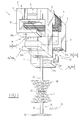
- the electromagnetic valve actuator shown in Figure 1 comprises an electromagnet 1 comprising a body made of magnetic material 2 carrying a supply coil 3.
- the body 2 essentially comprises two pole pieces 4.5 between which is arranged a permanent magnet 6 whose polarization direction indicated by arrow 7 is perpendicular to the direction of the magnetic field generated by the supply coil 3.
- Each of the pole pieces 4.5 advantageously made of ferrite, or of material based on agglomerated iron powder has a central part 8.9 around which pass the turns of the supply coil 3 which surrounds also the permanent magnet 6.
- branches 10, 11, 12 and 13 perpendicular to said central parts 8, 9 and to the magnet permanent 6.
- a branch 10.12 of each pole piece 4.5 is a branch short and a branch 11.13 of each pole piece is a long branch.
- the short branch 10 of the pole piece 4 and the long branch 13 of the pole piece 5, extend from the ends of the central zones 8 and 9 located opposite each other.
- the long branch 11 of the pole piece 4 and the short branch 12 of the pole piece 5 extend from the other ends of the central zones 8 and 9 located opposite each other.
- Each of the branches 10 to 13 of the pole pieces 4.5 has a respective end 10a to 13a perpendicular to the corresponding branch, from so that each of these branches has an L shape.
- the short branches 10 and 12 form with the long branches 11.13 respectively, air gaps 14.15 whose value corresponds to the lifting of a valve to operate.
- the actuating rod 17 and the tail 19 of the valve 18 are surrounded by two return springs 20,21, the ends of which lie opposite one on the other, bear on a part 22 connecting the actuating rod 17 and the valve stem 19 of the valve 18.
- the head 23 of the valve 18 cooperates with a non-valve seat depicted of an engine cylinder head 24.
- the short branches 10 and 12 of the pole pieces 4 and 5 define with the plate 16, a high magnetic circuit.
- Long branches 11 and 13 form with the magnetic plate 16, a low magnetic circuit.
- the plate 16 and the branches short and long in turn define air gaps e1, e2 whose sum is equal to the lift L of the valve, this lift being equal to the difference between the air gap 14.15 between each short branch and each respective long branch pole pieces 4 and 5 and the thickness of the plate 16.
- a negative current is applied to the coil 3.
- the plate 16 peels off and is pushed back by the lower spring 21 which brings speed and compresses the upper spring 20.
- the plateau describes a sinusoidal type trajectory typical of a system harmonic in free oscillation.
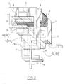
- the actuator of Figure 3 differs from that of Figure 1 in that it comprises two supply coils 30,31 each wound around a branch of a pole piece 4.5.
- the supply coils 30, 31 are wound around the respective short branches 10.12 of the pole pieces 4.5.
- Said short branches 10,12 are located on the same side of the pallet magnetic 16.
- the coils 30, 31 are supplied so as to generate a flow of same direction as the flow generated by the coil 3 of the actuator of Figure 1 that they replace.
- the winding directions of the two coils 30,31 as well as the currents supply of these coils are such that the effects of the fields generated by these add up.
Landscapes
- Engineering & Computer Science (AREA)
- Physics & Mathematics (AREA)
- Electromagnetism (AREA)
- Power Engineering (AREA)
- Mechanical Engineering (AREA)
- General Engineering & Computer Science (AREA)
- Valve Device For Special Equipments (AREA)
- Magnetically Actuated Valves (AREA)
Abstract
Description
- le corps magnétique dudit électroaimant comprend deux pièces polaires entre lesquelles est disposé ledit aimant permanent, chaque pièce polaire comprenant transversalement à la direction de polarisation de l'aimant, une branche courte et une branche longue, les branches courte et longue d'une pièce polaire définissant des entrefers respectifs avec les branches longue et courte de l'autre pièce polaire, ladite armature étant montée déplaçable dans lesdits entrefers ;
- les branches courte et longue de chaque pièce polaire sont en forme de L, les extrémités libres des branches courte et longue d'une pièce polaire définissant lesdits entrefers avec les extrémités libres des branches longue et courte de l'autre pièce polaire ;
- les extrémités libres des branches des pièces polaires sont parallèles entre elles ;
- lesdites pièces polaires sont en ferrite, ou en matériau à base de poudre de fer agglomérée, ou en tout autre matériau ferromagnétique ;
- l'aimant permanent est disposé entre des parties centrales des pièces polaires et l'actionneur comporte une bobine d'alimentation enroulée autour desdites parties centrales des pièces polaires et de l'aimant ;
- l'aimant permanent est disposé entre les parties centrales desdites pièces polaires et l'actionneur comporte deux bobines d'alimentation portées chacune par une branche d'une pièce polaire correspondante, les branches des deux pièces polaires étant situées du même côté de ladite palette.
- la Fig.1 est une vue schématique en perspective d'un actionneur électromagnétique de soupape suivant l'invention en position de soupape ouverte;
- la Fig.2 est une vue analogue à celle de la figure 1 montrant l'actionneur en position de soupape fermée ; et
- la Fig.3 est une vue schématique en perspective d'un actionneur électromagnétique de soupape suivant un autre mode de réalisation de l'invention.
- Bih : induction magnétique créée par la bobine d'alimentation 3 dans l'entrefer e1 entre le circuit magnétique haut défini par les branches courtes 10,12 des pièces polaires 4 et 5 et la palette 16 ;
- Bib : induction magnétique créée par la bobine d'alimentation 3 dans l'entrefer e2 entre le circuit magnétique bas défini par les branches longues 11,13 des pièces polaires 4 et 5 et la palette 16.
- Ba : induction magnétique créée par l'aimant permanent 6.
Claims (7)
- Actionneur électromagnétique de soupape de moteur à combustion interne comprenant au moins un électroaimant comportant un corps, au moins une bobine d'alimentation (3;30,31), une palette magnétique (16) liée à un organe (17) d'entraínement de la soupape (18) à l'encontre de l'action d'au moins un ressort (20,21) de stockage d'énergie de commutation de ladite soupape, caractérisé en ce que dans le corps magnétique de l'électroaimant est interposé un aimant permanent (6) dont le champ est perpendiculaire au champ engendré dans ledit corps par ladite au moins une bobine d'alimentation (3;30,31).
- Actionneur électromagnétique suivant la revendication 1, caractérisé en ce que le corps magnétique (2) dudit électroaimant comprend deux pièces polaires (4,5) entre lesquelles est disposé ledit aimant permanent (6), chaque pièce polaire comprenant transversalement à la direction de polarisation de l'aimant (6), une branche courte (10,12) et une branche longue (11,13), les branches courte et longue (10,11) d'une pièce polaire (4) définissant des entrefers respectifs (14,15) avec les branches longue et courte (13,12) de l'autre pièce polaire (5), ladite palette (16) étant montée déplaçable dans lesdits entrefers.
- Actionneur électromagnétique suivant la revendication 2, caractérisé en ce que les branches courte et longue (10,12,11,13) de chaque pièce polaire sont en forme de L, les extrémités libres (10a,11a) des branches courte et longue (10,11) d'une pièce polaire (4) définissant lesdits entrefers (14,15) avec les extrémités libres (13a,12a) des branches longue et courte (13,12) de l'autre pièce polaire (5).
- Actionneur suivant l'une des revendications 2 et 3, caractérisé en ce que les extrémités libres (10a,11a,12a,13a) des branches des pièces polaires (4,5) sont parallèles entre elles.
- Actionneur suivant l'une des revendications 2 à 4, caractérisé en ce que lesdites pièces polaires (4,5) sont en ferrite ou en matériau à base de poudre de fer agglomérée.
- Actionneur suivant l'une des revendications 1 à 5, caractérisé en ce que l'aimant permanent (6) est disposé entre des parties centrales (8,9) des pièces polaires (4,5) et en ce qu'il comporte une bobine d'alimentation (3) enroulée autour desdites parties centrales (8,9) des pièces polaires (4,5) et de l'aimant (6).
- Actionneur suivant l'une des revendications 2 à 5, caractérisé en ce que l'aimant permanent (6) est disposé entre des parties centrales (8,9) desdites pièces polaires (4,5) et en ce qu'il comporte deux bobines d'alimentation (30,31) portées chacune par une branche (10,12) d'une pièce polaire (4,5) correspondante, les branches (10,12) des deux pièces polaires (4,5) étant situées du même côté de ladite palette (16).
Applications Claiming Priority (2)
| Application Number | Priority Date | Filing Date | Title |
|---|---|---|---|
| FR0101372A FR2820238B1 (fr) | 2001-02-01 | 2001-02-01 | Actionneur electromagnetique a un electroaimant pour soupape de moteur a combustion interne |
| FR0101372 | 2001-02-01 |
Publications (2)
| Publication Number | Publication Date |
|---|---|
| EP1229560A1 true EP1229560A1 (fr) | 2002-08-07 |
| EP1229560B1 EP1229560B1 (fr) | 2009-01-14 |
Family
ID=8859507
Family Applications (1)
| Application Number | Title | Priority Date | Filing Date |
|---|---|---|---|
| EP02290176A Expired - Lifetime EP1229560B1 (fr) | 2001-02-01 | 2002-01-24 | Actionneur électromagnétique à un électroaimant pour soupape de moteur à combustion interne |
Country Status (5)
| Country | Link |
|---|---|
| EP (1) | EP1229560B1 (fr) |
| AT (1) | ATE421156T1 (fr) |
| DE (1) | DE60230827D1 (fr) |
| ES (1) | ES2317982T3 (fr) |
| FR (1) | FR2820238B1 (fr) |
Families Citing this family (2)
| Publication number | Priority date | Publication date | Assignee | Title |
|---|---|---|---|---|
| US7124720B2 (en) | 2004-03-25 | 2006-10-24 | Ford Global Technologies, Llc | Permanent magnet electromagnetic actuator for an electronic valve actuation system of an engine |
| US7249579B2 (en) | 2004-03-25 | 2007-07-31 | Ford Global Technologies, Llc | Enhanced permanent magnet electromagnetic actuator for an electronic valve actuation system of an engine |
Citations (4)
| Publication number | Priority date | Publication date | Assignee | Title |
|---|---|---|---|---|
| GB2149975A (en) * | 1983-11-16 | 1985-06-19 | Telemecanique Electrique | Electromagnetic device comprising a permanent magnet |
| US4749167A (en) * | 1979-12-03 | 1988-06-07 | Martin Gottschall | Two position mechanism |
| WO1992002712A1 (fr) * | 1990-07-27 | 1992-02-20 | Keith Leslie Richards | Dispositif de commande de soupape |
| US5153472A (en) * | 1991-07-19 | 1992-10-06 | International Business Machines Corporation | Probe positioning actuator |
-
2001
- 2001-02-01 FR FR0101372A patent/FR2820238B1/fr not_active Expired - Fee Related
-
2002
- 2002-01-24 DE DE60230827T patent/DE60230827D1/de not_active Expired - Lifetime
- 2002-01-24 ES ES02290176T patent/ES2317982T3/es not_active Expired - Lifetime
- 2002-01-24 EP EP02290176A patent/EP1229560B1/fr not_active Expired - Lifetime
- 2002-01-24 AT AT02290176T patent/ATE421156T1/de not_active IP Right Cessation
Patent Citations (4)
| Publication number | Priority date | Publication date | Assignee | Title |
|---|---|---|---|---|
| US4749167A (en) * | 1979-12-03 | 1988-06-07 | Martin Gottschall | Two position mechanism |
| GB2149975A (en) * | 1983-11-16 | 1985-06-19 | Telemecanique Electrique | Electromagnetic device comprising a permanent magnet |
| WO1992002712A1 (fr) * | 1990-07-27 | 1992-02-20 | Keith Leslie Richards | Dispositif de commande de soupape |
| US5153472A (en) * | 1991-07-19 | 1992-10-06 | International Business Machines Corporation | Probe positioning actuator |
Also Published As
| Publication number | Publication date |
|---|---|
| EP1229560B1 (fr) | 2009-01-14 |
| ATE421156T1 (de) | 2009-01-15 |
| DE60230827D1 (de) | 2009-03-05 |
| FR2820238A1 (fr) | 2002-08-02 |
| ES2317982T3 (es) | 2009-05-01 |
| FR2820238B1 (fr) | 2003-05-09 |
Similar Documents
| Publication | Publication Date | Title |
|---|---|---|
| EP1121511B1 (fr) | Procede et dispositif d'actionnement electromagnetique de soupape | |
| EP1174595A1 (fr) | Actionneur de soupapes de moteurs à combustion interne | |
| EP0992658B1 (fr) | Actionneur électromagnétique de soupape | |
| EP1174596B1 (fr) | Actionneur électromagnétique de soupape de moteur à combustion interne | |
| EP1450011B1 (fr) | Actionneur électromécanique de commande de soupape pour moteur interne et moteur à combustion interne muni d'un tel actionneur | |
| EP1229560B1 (fr) | Actionneur électromagnétique à un électroaimant pour soupape de moteur à combustion interne | |
| EP1421590B1 (fr) | Actionneur electromagnetique a deux positions stables de fin de course, notamment pour la commande de vannes de conduits d'admission d'air pour moteurs a combustion interne | |
| WO2002084082A1 (fr) | Dispositif de commande de soupape a point mort | |
| FR2873232A1 (fr) | Dispositif de commande electromagnetique fonctionnant en basculement | |
| FR2797297A1 (fr) | Dispositif d'actionnement de soupape electrodynamique | |
| FR2784222A1 (fr) | Actionneur electromagnetique de soupape | |
| FR2886669A1 (fr) | Electrovanne | |
| EP1568858B1 (fr) | Dispositif d'actionnement électromagnétique de soupape pour moteur à combustion interne | |
| CA3197790A1 (fr) | Actionneur electromagnetique bistable et valve de frein d'aeronef equipee d'un tel actionneur | |
| FR2811369A1 (fr) | Dispositif d'entrainement lineaire d'une soupape au moyen d'aimants permanents | |
| WO2005075796A1 (fr) | Dispositif de commande à électroaimant pour une soupape de moteur à combustion interne | |
| EP1215370A1 (fr) | Dispositif d'entrainement lineaire d'une soupape au moyen d'aimants mobiles | |
| EP1122748A1 (fr) | Dispositif pour contrôler et réduire la vitesse d'impact d'un actionneur électromécanique | |
| WO1997026667A1 (fr) | Actionneur electromagnetique monophase rotatif a ressort magnetique et vanne electrique mettant en oeuvre un tel actionneur | |
| FR2818431A1 (fr) | Dispositif d'entrainement lineaire d'une soupape au moyen d'aimants mobiles | |
| FR3071678A1 (fr) | Convertisseur d'energie electromagnetique | |
| FR3047513B1 (fr) | Actionneur electromagnetique pour soupape de moteur a combustion interne | |
| FR2849466A1 (fr) | Ationneur lineaire de soupape comportant un aimant mobile dans un entrefer magnetique | |
| FR2811467A1 (fr) | Actionneur de soupape electrodynamique et agencement d'une pluralite de tels actionneurs | |
| WO2016051040A1 (fr) | Actionneur electromagnetique a trois bobines |
Legal Events
| Date | Code | Title | Description |
|---|---|---|---|
| PUAI | Public reference made under article 153(3) epc to a published international application that has entered the european phase |
Free format text: ORIGINAL CODE: 0009012 |
|
| AK | Designated contracting states |
Kind code of ref document: A1 Designated state(s): AT BE CH CY DE DK ES FI FR GB GR IE IT LI LU MC NL PT SE TR |
|
| AX | Request for extension of the european patent |
Free format text: AL;LT;LV;MK;RO;SI |
|
| 17P | Request for examination filed |
Effective date: 20030110 |
|
| AKX | Designation fees paid |
Designated state(s): AT BE CH CY DE DK ES FI FR GB GR IE IT LI LU MC NL PT SE TR |
|
| GRAP | Despatch of communication of intention to grant a patent |
Free format text: ORIGINAL CODE: EPIDOSNIGR1 |
|
| GRAS | Grant fee paid |
Free format text: ORIGINAL CODE: EPIDOSNIGR3 |
|
| GRAA | (expected) grant |
Free format text: ORIGINAL CODE: 0009210 |
|
| AK | Designated contracting states |
Kind code of ref document: B1 Designated state(s): AT BE CH CY DE DK ES FI FR GB GR IE IT LI LU MC NL PT SE TR |
|
| REG | Reference to a national code |
Ref country code: GB Ref legal event code: FG4D Free format text: NOT ENGLISH |
|
| REG | Reference to a national code |
Ref country code: CH Ref legal event code: EP |
|
| REG | Reference to a national code |
Ref country code: IE Ref legal event code: FG4D Free format text: LANGUAGE OF EP DOCUMENT: FRENCH |
|
| REF | Corresponds to: |
Ref document number: 60230827 Country of ref document: DE Date of ref document: 20090305 Kind code of ref document: P |
|
| REG | Reference to a national code |
Ref country code: GB Ref legal event code: 746 Effective date: 20090226 |
|
| REG | Reference to a national code |
Ref country code: ES Ref legal event code: FG2A Ref document number: 2317982 Country of ref document: ES Kind code of ref document: T3 |
|
| PG25 | Lapsed in a contracting state [announced via postgrant information from national office to epo] |
Ref country code: NL Free format text: LAPSE BECAUSE OF FAILURE TO SUBMIT A TRANSLATION OF THE DESCRIPTION OR TO PAY THE FEE WITHIN THE PRESCRIBED TIME-LIMIT Effective date: 20090114 |
|
| NLV1 | Nl: lapsed or annulled due to failure to fulfill the requirements of art. 29p and 29m of the patents act | ||
| PG25 | Lapsed in a contracting state [announced via postgrant information from national office to epo] |
Ref country code: FI Free format text: LAPSE BECAUSE OF FAILURE TO SUBMIT A TRANSLATION OF THE DESCRIPTION OR TO PAY THE FEE WITHIN THE PRESCRIBED TIME-LIMIT Effective date: 20090114 |
|
| REG | Reference to a national code |
Ref country code: IE Ref legal event code: FD4D |
|
| PG25 | Lapsed in a contracting state [announced via postgrant information from national office to epo] |
Ref country code: SE Free format text: LAPSE BECAUSE OF FAILURE TO SUBMIT A TRANSLATION OF THE DESCRIPTION OR TO PAY THE FEE WITHIN THE PRESCRIBED TIME-LIMIT Effective date: 20090414 Ref country code: MC Free format text: LAPSE BECAUSE OF NON-PAYMENT OF DUE FEES Effective date: 20090131 Ref country code: AT Free format text: LAPSE BECAUSE OF FAILURE TO SUBMIT A TRANSLATION OF THE DESCRIPTION OR TO PAY THE FEE WITHIN THE PRESCRIBED TIME-LIMIT Effective date: 20090114 Ref country code: PT Free format text: LAPSE BECAUSE OF FAILURE TO SUBMIT A TRANSLATION OF THE DESCRIPTION OR TO PAY THE FEE WITHIN THE PRESCRIBED TIME-LIMIT Effective date: 20090615 |
|
| REG | Reference to a national code |
Ref country code: CH Ref legal event code: PL |
|
| PG25 | Lapsed in a contracting state [announced via postgrant information from national office to epo] |
Ref country code: IE Free format text: LAPSE BECAUSE OF FAILURE TO SUBMIT A TRANSLATION OF THE DESCRIPTION OR TO PAY THE FEE WITHIN THE PRESCRIBED TIME-LIMIT Effective date: 20090114 Ref country code: CH Free format text: LAPSE BECAUSE OF NON-PAYMENT OF DUE FEES Effective date: 20090131 Ref country code: DK Free format text: LAPSE BECAUSE OF FAILURE TO SUBMIT A TRANSLATION OF THE DESCRIPTION OR TO PAY THE FEE WITHIN THE PRESCRIBED TIME-LIMIT Effective date: 20090114 Ref country code: LI Free format text: LAPSE BECAUSE OF NON-PAYMENT OF DUE FEES Effective date: 20090131 |
|
| PLBE | No opposition filed within time limit |
Free format text: ORIGINAL CODE: 0009261 |
|
| STAA | Information on the status of an ep patent application or granted ep patent |
Free format text: STATUS: NO OPPOSITION FILED WITHIN TIME LIMIT |
|
| 26N | No opposition filed |
Effective date: 20091015 |
|
| PG25 | Lapsed in a contracting state [announced via postgrant information from national office to epo] |
Ref country code: BE Free format text: LAPSE BECAUSE OF NON-PAYMENT OF DUE FEES Effective date: 20090131 |
|
| PG25 | Lapsed in a contracting state [announced via postgrant information from national office to epo] |
Ref country code: GR Free format text: LAPSE BECAUSE OF FAILURE TO SUBMIT A TRANSLATION OF THE DESCRIPTION OR TO PAY THE FEE WITHIN THE PRESCRIBED TIME-LIMIT Effective date: 20090415 |
|
| PG25 | Lapsed in a contracting state [announced via postgrant information from national office to epo] |
Ref country code: LU Free format text: LAPSE BECAUSE OF NON-PAYMENT OF DUE FEES Effective date: 20090124 |
|
| PG25 | Lapsed in a contracting state [announced via postgrant information from national office to epo] |
Ref country code: TR Free format text: LAPSE BECAUSE OF FAILURE TO SUBMIT A TRANSLATION OF THE DESCRIPTION OR TO PAY THE FEE WITHIN THE PRESCRIBED TIME-LIMIT Effective date: 20090114 |
|
| PG25 | Lapsed in a contracting state [announced via postgrant information from national office to epo] |
Ref country code: CY Free format text: LAPSE BECAUSE OF FAILURE TO SUBMIT A TRANSLATION OF THE DESCRIPTION OR TO PAY THE FEE WITHIN THE PRESCRIBED TIME-LIMIT Effective date: 20090114 |
|
| REG | Reference to a national code |
Ref country code: ES Ref legal event code: GC2A Effective date: 20130213 |
|
| REG | Reference to a national code |
Ref country code: FR Ref legal event code: PLFP Year of fee payment: 15 |
|
| REG | Reference to a national code |
Ref country code: FR Ref legal event code: PLFP Year of fee payment: 16 |
|
| REG | Reference to a national code |
Ref country code: FR Ref legal event code: PLFP Year of fee payment: 17 |
|
| REG | Reference to a national code |
Ref country code: FR Ref legal event code: CA Effective date: 20180312 Ref country code: FR Ref legal event code: CD Owner name: PEUGEOT CITROEN AUTOMOBILES SA, FR Effective date: 20180312 |
|
| PGFP | Annual fee paid to national office [announced via postgrant information from national office to epo] |
Ref country code: IT Payment date: 20190102 Year of fee payment: 18 |
|
| PG25 | Lapsed in a contracting state [announced via postgrant information from national office to epo] |
Ref country code: IT Free format text: LAPSE BECAUSE OF NON-PAYMENT OF DUE FEES Effective date: 20200124 |
|
| PGFP | Annual fee paid to national office [announced via postgrant information from national office to epo] |
Ref country code: GB Payment date: 20201218 Year of fee payment: 20 Ref country code: FR Payment date: 20201217 Year of fee payment: 20 |
|
| PGFP | Annual fee paid to national office [announced via postgrant information from national office to epo] |
Ref country code: DE Payment date: 20201217 Year of fee payment: 20 |
|
| REG | Reference to a national code |
Ref country code: ES Ref legal event code: FD2A Effective date: 20210604 |
|
| PG25 | Lapsed in a contracting state [announced via postgrant information from national office to epo] |
Ref country code: ES Free format text: LAPSE BECAUSE OF NON-PAYMENT OF DUE FEES Effective date: 20200125 |
|
| REG | Reference to a national code |
Ref country code: DE Ref legal event code: R071 Ref document number: 60230827 Country of ref document: DE |
|
| REG | Reference to a national code |
Ref country code: GB Ref legal event code: PE20 Expiry date: 20220123 |
|
| PG25 | Lapsed in a contracting state [announced via postgrant information from national office to epo] |
Ref country code: GB Free format text: LAPSE BECAUSE OF EXPIRATION OF PROTECTION Effective date: 20220123 |