EP1229691A2 - Einstellung von Umgebung-Parametern in tragbaren Geräten - Google Patents
Einstellung von Umgebung-Parametern in tragbaren Geräten Download PDFInfo
- Publication number
- EP1229691A2 EP1229691A2 EP02250773A EP02250773A EP1229691A2 EP 1229691 A2 EP1229691 A2 EP 1229691A2 EP 02250773 A EP02250773 A EP 02250773A EP 02250773 A EP02250773 A EP 02250773A EP 1229691 A2 EP1229691 A2 EP 1229691A2
- Authority
- EP
- European Patent Office
- Prior art keywords
- command
- computer
- time
- storage device
- data storage
- Prior art date
- Legal status (The legal status is an assumption and is not a legal conclusion. Google has not performed a legal analysis and makes no representation as to the accuracy of the status listed.)
- Ceased
Links
Images




Classifications
-
- H—ELECTRICITY
- H04—ELECTRIC COMMUNICATION TECHNIQUE
- H04N—PICTORIAL COMMUNICATION, e.g. TELEVISION
- H04N5/00—Details of television systems
- H04N5/76—Television signal recording
- H04N5/765—Interface circuits between an apparatus for recording and another apparatus
- H04N5/77—Interface circuits between an apparatus for recording and another apparatus between a recording apparatus and a television camera
- H04N5/772—Interface circuits between an apparatus for recording and another apparatus between a recording apparatus and a television camera the recording apparatus and the television camera being placed in the same enclosure
-
- H—ELECTRICITY
- H04—ELECTRIC COMMUNICATION TECHNIQUE
- H04L—TRANSMISSION OF DIGITAL INFORMATION, e.g. TELEGRAPHIC COMMUNICATION
- H04L9/00—Cryptographic mechanisms or cryptographic arrangements for secret or secure communications; Network security protocols
- H04L9/40—Network security protocols
-
- H—ELECTRICITY
- H04—ELECTRIC COMMUNICATION TECHNIQUE
- H04N—PICTORIAL COMMUNICATION, e.g. TELEVISION
- H04N23/00—Cameras or camera modules comprising electronic image sensors; Control thereof
- H04N23/60—Control of cameras or camera modules
- H04N23/66—Remote control of cameras or camera parts, e.g. by remote control devices
-
- H—ELECTRICITY
- H04—ELECTRIC COMMUNICATION TECHNIQUE
- H04L—TRANSMISSION OF DIGITAL INFORMATION, e.g. TELEGRAPHIC COMMUNICATION
- H04L69/00—Network arrangements, protocols or services independent of the application payload and not provided for in the other groups of this subclass
- H04L69/28—Timers or timing mechanisms used in protocols
-
- H—ELECTRICITY
- H04—ELECTRIC COMMUNICATION TECHNIQUE
- H04N—PICTORIAL COMMUNICATION, e.g. TELEVISION
- H04N5/00—Details of television systems
- H04N5/76—Television signal recording
- H04N5/765—Interface circuits between an apparatus for recording and another apparatus
- H04N5/77—Interface circuits between an apparatus for recording and another apparatus between a recording apparatus and a television camera
-
- H—ELECTRICITY
- H04—ELECTRIC COMMUNICATION TECHNIQUE
- H04N—PICTORIAL COMMUNICATION, e.g. TELEVISION
- H04N5/00—Details of television systems
- H04N5/76—Television signal recording
- H04N5/78—Television signal recording using magnetic recording
- H04N5/782—Television signal recording using magnetic recording on tape
- H04N5/7824—Television signal recording using magnetic recording on tape with rotating magnetic heads
- H04N5/7826—Television signal recording using magnetic recording on tape with rotating magnetic heads involving helical scanning of the magnetic tape
- H04N5/78263—Television signal recording using magnetic recording on tape with rotating magnetic heads involving helical scanning of the magnetic tape for recording on tracks inclined relative to the direction of movement of the tape
-
- H—ELECTRICITY
- H04—ELECTRIC COMMUNICATION TECHNIQUE
- H04N—PICTORIAL COMMUNICATION, e.g. TELEVISION
- H04N5/00—Details of television systems
- H04N5/76—Television signal recording
- H04N5/91—Television signal processing therefor
- H04N5/92—Transformation of the television signal for recording, e.g. modulation, frequency changing; Inverse transformation for playback
- H04N5/9201—Transformation of the television signal for recording, e.g. modulation, frequency changing; Inverse transformation for playback involving the multiplexing of an additional signal and the video signal
Definitions
- the present invention relates to a method of setting an environment parameter in a portable data storage device, e.g., a digital video camcorder, a personal digital assistant (PDA), a portable music player, or the like.
- a portable data storage device e.g., a digital video camcorder, a personal digital assistant (PDA), a portable music player, or the like.
- PDA personal digital assistant
- portable data storage devices receive, store and reproduce data, typically in the form of digital signals.
- a digital video camcorder (hereinafter "DVC") records and reproduces video and audio data.
- the DVC has advantages over an analog type device in terms of high video and audio quality and easy storage and editing.
- a number of operational keys on an operation panel of the portable device is reduced and simplified.
- the one button is used for a plurality of functions, typically requiring the user to operate buttons in a particular sequence, including pressing one button a plurality of times at different points in the sequence, to select a desired function.
- a portable device may be made to connect with and to exchange data to and from a host computer, e.g. a PC
- the data allowed to be exchanged is limited to application related data, e.g., the audio/video data in the case of the DVC, contact, schedule and/or appointment data of a PDA, or one or more music files in the case of a portable music player, e.g., an MP3 player, etc.
- a user must still use the less convenient input interface of the portable device in order to set the operation environment, e.g., the configuration setting preference, the time and date setting or the like, of the portable device itself,
- a user of a DVC may encounter difficulty in setting a recording/reproducing method selection, a video/audio recording pattern selection, and a time setting selection, using the input buttons of the DVC.
- the aim of the present invention is to ameliorate the aforementioned problem.
- a method according to the present invention is characterised by establishing a communications link between the portable data storage device and a host computer, transmitting a signal from the host computer to the portable data storage device, said signal containing a code indicating that it carries an environment parameter setting value and an environment parameter setting value, and setting an environment parameter in the portable data storage device in dependence on said code and said environment parameter setting value.
- Said signal may be structured substantially according to IEEE-1394.
- the environment parameter may be time.
- a method of setting the environment for a portable data storage device that has an interface for interfacing with a host computer thereby enabling a mutual data transmission with the host computer, comprises: assigning an environment setting command code to at least one code in a reserved area that is not in use in a code area available for assignment of commands for the mutual data transmission between the portable device and the host computer via the interface; preparing an operation code area and an operand area in a command frame transmitted between the host computer and the portable device, the operation code area containing the environment setting command code, the operand area containing environment setting data corresponding to the environment setting command code; determining whether the code contained in the operation code area of the command frame is the environment setting command code where the command frame is transmitted from the host computer to the portable device; and upon determining the code contained in the operation code area of the command frame being the environment setting command code, updating the existing environment setting data of the portable device with the environment setting data contained in the operand area.
- the environment setting commands may be a time setting command while the environment setting data may be the time data corresponding to the time setting command.
- the time data may be the data relating to the time keeping in the host computer, which in turn may sometimes be downloaded from a remote time server that provides the standard time data, over the Internet or the like.
- the time data may be used as the time stamp recorded in a time recording sector of a magnetic tape during a recording.
- the environment setting data such as for example, the time data
- the portable device is easily inputted to the portable device by using the host computer. Accordingly, without complicated manipulation of key buttons of the portable device, the environments configuration for the portable device can be set.
- a digital video camcorder comprises an interface which enables mutual transmission of digital data with a host computer; a microcomputer which counts a current time based on time data transmitted from the host computer via the interface.
- the digital video camcorder may also comprises a head which records audio/video data on a magnetic tape during audio/video data recording and records the current time counted by the microcomputer on a predetermined part of the magnetic tape.
- Figure 1 shows a connection between a digital video camcorder (DVC) 100 and a personal computer 200 and Figure 2 is a detailed block diagram of the connection between the DVC 100 and the computer 200 shown in Figure 1.
- the DVC 100 is connected to the computer 200, and the computer 200 is connected to a time server 230 via the Internet 220.
- the DVC 100 comprises a microcomputer 90 which controls overall operation of sub-devices, a key input portion 85 through which a user inputs various control commands regarding operation of the DVC 100, a camera 10 which captures image and acquires sound to obtain video and audio data for a scene, a camera interface 20 which interfaces between the microcomputer 90 and the camera 10, a magnetic tape 80 which stores the video and audio data obtained by the camera 10 and additional data, a head 70 which records data on the magnetic tape 80 and reproduces recorded data from the magnetic tape 80, a mechanical driving portion 30 which mechanically drives the head 70 and the magnetic tape 80, an error checking portion 60 which checks for errors in the signal read by the head 70 and in the signals to be recorded on the magnetic tape 80, and a data compressing/decompressing portion 50 which compresses output data of the camera interface 20 and decompresses the data read by the head 70.
- a microcomputer 90 which controls overall operation of sub-devices
- a key input portion 85 through which a user inputs various control commands regarding operation of
- the DVC 100 further comprises an environment data storage portion 95, which stores environment setting data, and a digital interface 40 which provides an interface between the computer 200 and the DVC 100 so that digital data is receivable from the computer 200 and storable in the environment data storage portion 95.
- the computer 200 is connected to the digital interface 40 of the DVC 100 through, for example, a cable 110 for the exchange of data between the computer 200 and the DVC 100.
- the environment data storage portion 95 preferably employs a non-volatile memory to prevent erasure of data during power cut-off.
- the digital interface 40 between the DVC 100 and the computer 200 communicates data including video and/or audio data between the DVC 100 and the computer 200.
- image and audio data acquired by the DVC 100 is transmitted to the computer 200 via the digital interface 40.
- Image and audio data edited or prestored in the computer 200 is also transmitted to the DVC 100 for reproduction via the digital interface 40.
- the computer 200 transmits control data to the DVC 100 to control respective operations of the DVC 100, such as for example, recording, reproducing, fast forward, rewind, etc.
- a separate communication protocol is defined, such as, for example, the IEEE-1394 protocol.
- the IEEE-1394 protocol specifies various control commands to control the respective devices using the computer 200, according to which the operation of the DVC 100 is controlled through the computer 200. It should be understood, however, that any other communication protocol may be utilised.
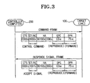
- the IEEE-1394 protocol labels a device that sends a control command a "controller”, and a device that receives the control command from the controller a "target”. As shown in Figure 3, the computer 200 acts as a controller while the DVC 100 acts as a target.
- the IEEE-1394 protocol specifies the structure of the command frame transmitted between the controller and the target, the relevant portions of which will now be described in greater detail, and in reference to Figure 3.
- each command frame contains five code fields, i.e. a command and transaction set (CTS) field, a command type/response code (CT/RC) field, a header address (HA) field, an operation code (OPC) field and an operand (OPR) field.
- CTS command and transaction set
- C/RC command type/response code
- HA header address
- OPC operation code
- OCR operand
- the CTS field indicates types of control command.
- the command frame is an audio/video control (A/VC) frame.
- the computer 200 transmits to the DVC 100 a control command for controlling the sub-devices of the DVC 100 , which is an audio/video device, the CTS field is always assigned the value 0000 2 .
- the CT/RC field indicates whether the frame is a command from the computer 200 or a response code from the DVC 100, and also indicates the category of the commands transmitted. More specifically, if the most significant bit (MSB) of the CT/RC field is zero (0), the frame is a command frame from the computer 200. If the MSB of the CT/RC field is one (1), the frame is a response code transmitted from the DVC 100. If the CT/RC field equals 0000 2 , the command from the computer 200 is categorized as a control command, and, if the CT/RC field equals 1001 2 , the response code from the DVC 100 is categorized as an accept signal to the command frame from the computer 200.
- MSB most significant bit
- the HA field has a code that specifies the target device or one of sub-devices in the target device, which is the object of the control. For example, if the code of the HA field equals to 00100 2 , it specifies a video cassette recorder as the object of the control.
- the OPC field has a code that specifies detailed operation of the device or a subdevice, and the OPR field has a parameter corresponding to the OPC field.
- the OPC and OPR fields are the primary contents of the frame regarding a command or a response.
- the OPC field is assigned with one (1) byte and the OPR field is assigned with more than one (1) byte. For example, if the OPC is 'C3 16 ' and the OPR is '75 16 ', the OPC indicates a 'forward reproducing'.
- the DVC 100 receives the command frame shown in Figure 3 from the computer 200
- the DVC 100 generates a response frame by converting the code of the CT/RC field into a code indicating the frame as a response frame and maintaining codes of remaining fields at the same values as the initial values in the received command frame, and transmits the newly generated response frame to the computer 200.
- the computer 200 determines the frame as a normal transmission of the command, and performs the forward reproducing of the DVC 100.
- Figure 4 shows an OPC map defined by the current IEEE-1394 protocol.
- One (1) byte code of the OPC field consists of four-bit higher nibble and four-bit lower nibble.
- the one (1) byte OPC is a combination of an upper nibble and a lower nibble, and corresponds to a command code representing each different command.
- no command corresponds to the fields of upper nibble of 8 16 , 9 16 , E 16 and F 16 .
- the 8 16 , 9 16 , E 16 and F 16 fields are reserved fields, which are not presently used to define a command. Accordingly, in an exemplary embodiment of the present invention, in order to re-define an environment setting command from the computer 200, the code values of the reserved field are used to define the environment setting commands OPC. If the OPC field contains an environment setting command, the OPR field contains data associated with the environment setting command.
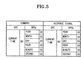
- the contents of the OPC and OPR fields for an exemplary environment setting command are shown in Figure 5.
- "COMMAND” represents a part of a frame transmitted from the computer 200 to the DVC 100
- RESPONSE SIGNAL represents a part of a frame transmitted from the DVC 100 to the computer 200.
- the OPC and OPR are especially related to a time setting command among the environment setting commands.
- a code 80 16 in the reserved field is defined as the OPC for a time setting command. That is, where the OPC is '80 16 ', the OPC indicates that data representing the current time is being transmitted.
- the OPR field contains data about the year, the month, the day, the hour, the minute and the second corresponding to the current time.
- the data about the year contains values ranging from '00' to '99', the month from '01' to '12', the day from '01' to '31', the hour from '00' to '23', the minute from '00' to '59' and the second from '00' to '59'.
- the OPR field is assigned a proper amount of bits necessary to hold data about the year, the month, the day, the hour, the minute and the second.
- the structure of the response frame is identical with a structure of the command frame.
- the response frame is transmitted from the DVC 100 to the computer 200 to confirm reception of the command frame, and accordingly, the computer 200 determines that the command frame is transmitted to the DVC 100 without an error if the computer receives the response frame having the same OPC and OPR as those of the command frame.
- Figure 5 shows the OPC and OPR for time data transmission by way of example only, however, other data for the environment setting are transmittable, by appropriately assigning the OPC other codes in the reserved field (e.g., code '81 16 ') and by defining the corresponding codes of the OPR.
- the reserved field e.g., code '81 16 '
- codes in the reserved field to define commands for the environment setting, configuring the environment for the DVC 100 is accomplished , without any conflict with other commands for performing functions of the IEEE-1394 protocol.
- codes for environment settings may be independently defined and used, without the use of the IEEE-1394 protocol.
- the microcomputer 90 in the DVC 100 checks through the digital interface 40 to see whether the DVC 100 is connected to the computer 200 at operation S10, and if it is determined that the DVC 100 is connected to the computer 200, DVC 100 transmits a command requesting a time data transmission to the computer 200 to receive the data for the current time at operation S20.
- the computer 200 converts the time data of the computer 200 to meet the communication protocol, e.g., the IEEE-1394 protocol at operation S30.
- the computer 200 converts the time data into the command frame of Figures 3 and 5 according to the IEEE-1394 protocol, and transmits the converted frame to the DVC 100 at operation S40.
- the command for time data setting is contained in the OPC field, while the time data is contained in the OPR field.
- the microcomputer 90 in the DVC 100 receives the command frame through the digital interface 40 at operation S50, and transmits a response frame corresponding to the command frame to the computer 200 at operation S60.
- the computer 200 determines at operation S70 whether the response frame contains the content corresponding to the command frame the computer 200 has transmitted. Where a discrepancy between the command frame the computer 200 transmitted and the response frame received from the DVC 100 is determined, the computer 200 takes corrective measures, such as for example, returning to operation S40 and retransmitting the command frame to the DVC 100, or the like.
- the DVC 100 analyzes the OPC of the command frame at operation S80. If the OPC contains '80 16 ' corresponding to the time setting command, the microcomputer 90 sets current time by extracting data from the OPR and storing the extracted data in the environment data storage portion 95 at operation S90 (step S90). If the OPC contains a code other than '80 16 ', the DVC 100 performs an operation corresponding to the command indicated by the received code at operation S95.
- the computer 200 is connectable to a time server 230 that provides standard time data via the Internet 220.
- the computer 200 downloads the standard time from the time server 230 using a known data downloading process, e.g. by using the TCP/IP, FTP protocols or the like. If the time data stored in the computer 200 does not correspond to the standard time of the time server, the computer 200 downloads the standard time from the time server 230 and then transmits the downloaded standard time to the DVC 100. Finally, in step 90, the data representing the current time previously stored in the environment data storage portion 95 is replaced by the time data received newly from the computer 200, and accordingly, the environment setting data of the DVC 100 is updated.
- the microcomputer 90 of the DVC 100 counts a current time based on the updated time data by using an internal clock. Accordingly, after the update of the time, the microcomputer 90 displays a current time outside of the DVC 100 or use the updated time for other purposes. In this manner, the time maintained by the microcomputer 90 is more accurately synchronized with the time of the computer 200 and/or with the standard time provided by the time server 230.
- the DVC 100 uses the updated time data for recording 'the time stamps' on the magnetic tape 80.
- the DVC 100 also records types of information other than the video/audio data on the magnetic tape 80.
- Time data is one example of the additional data recorded on the magnetic tape 80.
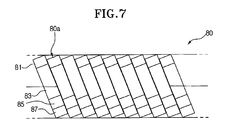
- the magnetic tape 80 has a plurality of tracks 80a inclining at a predetermined angle relative to a traveling direction.
- Each track 80a comprises four (4) sectors, i.e., a subcode sector 81, a video sector 83, an audio sector 85 and an insert and track information (ITI) sector 87.
- ITI insert and track information
- the subcode sector 81 records information representing the date, the time and the index information, while the ITI sector 87 records track information.
- the video sector 83 records signals representing the video images, while the audio sector 85 records signals representing the sound.
- the microcomputer 90 drives the head 70 and the mechanical-driving portion 30 to record the data inputted through the camera interface 20 on the video sector 83 and the audio sector 85 of the magnetic tape 80 while simultaneously recording corresponding data on the subcode sector 81 and the ITI sector 87.
- the relevant data stored in the environment data storage portion 95 is used as the time data to be recorded on the subcode sector 81. That is, by using the updated time data stored in the environment data storage portion 95, the microcomputer 90 continuously counts the current time accurately, and records the counted current time on the subcode sector 81 using the head 70. Accordingly, the DVC 100 provides accurate time, and also an accurate time stamp for the recorded images during the operations of DVC 100.
- Transmitting time data is only an example of an application of the present invention, and accordingly, other environment setting data may also be transmitted from the computer 200 to the DVC 100.
- a separate dedicated program may be incorporated in the computer 200 to provide commands and data for the environment setting of the DVC.
- the user may conveniently input the environment setting data directly to the computer 200 using the more convenient input interface of the computer 200.
- the inputted data are transmitted to the DVC 100, and stored in the environment data storage portion 95 through the processes as described above.
- the user accesses a special-purpose web site on the Internet for DVC environment setting, and downloads the environment setting data.
- the web site may provide a user interface menu, though which data for a variety of environment settings.
Landscapes
- Engineering & Computer Science (AREA)
- Signal Processing (AREA)
- Multimedia (AREA)
- Computer Security & Cryptography (AREA)
- Computer Networks & Wireless Communication (AREA)
- Signal Processing For Digital Recording And Reproducing (AREA)
- Television Signal Processing For Recording (AREA)
Applications Claiming Priority (2)
| Application Number | Priority Date | Filing Date | Title |
|---|---|---|---|
| KR10-2001-0005463A KR100398878B1 (ko) | 2001-02-05 | 2001-02-05 | 컴퓨터를 이용한 디지털 비디오 캠코더의 환경설정방법 |
| KR2001005463 | 2001-02-05 |
Publications (2)
| Publication Number | Publication Date |
|---|---|
| EP1229691A2 true EP1229691A2 (de) | 2002-08-07 |
| EP1229691A3 EP1229691A3 (de) | 2003-09-17 |
Family
ID=19705348
Family Applications (1)
| Application Number | Title | Priority Date | Filing Date |
|---|---|---|---|
| EP02250773A Ceased EP1229691A3 (de) | 2001-02-05 | 2002-02-05 | Einstellung von Umgebung-Parametern in tragbaren Geräten |
Country Status (3)
| Country | Link |
|---|---|
| US (1) | US7187403B2 (de) |
| EP (1) | EP1229691A3 (de) |
| KR (1) | KR100398878B1 (de) |
Families Citing this family (8)
| Publication number | Priority date | Publication date | Assignee | Title |
|---|---|---|---|---|
| KR20060005585A (ko) * | 2004-07-13 | 2006-01-18 | 삼성전자주식회사 | Usb를 이용한 데이터 전송 장치 및 방법 |
| US20080270816A1 (en) * | 2007-04-25 | 2008-10-30 | Phison Electronics Corp. | Portable data storage apparatus and synchronization method for the same |
| WO2009149183A1 (en) * | 2008-06-03 | 2009-12-10 | Saje Holdings, Inc. | Device capable of recording, storing, manipulating, and transferring information |
| US8601526B2 (en) | 2008-06-13 | 2013-12-03 | United Video Properties, Inc. | Systems and methods for displaying media content and media guidance information |
| JP2010002189A (ja) * | 2008-06-18 | 2010-01-07 | Sanyo Electric Co Ltd | 電子機器 |
| US9014546B2 (en) | 2009-09-23 | 2015-04-21 | Rovi Guides, Inc. | Systems and methods for automatically detecting users within detection regions of media devices |
| JP5564983B2 (ja) * | 2010-02-25 | 2014-08-06 | 株式会社リコー | 機器管理システム、管理対象機器、情報提供方法、情報提供プログラム、及びそのプログラムを記録した記録媒体 |
| CN102638655A (zh) * | 2012-04-13 | 2012-08-15 | 天津三星光电子有限公司 | 一种具有防止误开启功能的数码摄像机 |
Citations (6)
| Publication number | Priority date | Publication date | Assignee | Title |
|---|---|---|---|---|
| EP0841776A1 (de) | 1996-11-12 | 1998-05-13 | Sony Corporation | Kommunikationsverfahren und elektronisches Gerät |
| JPH10285501A (ja) | 1997-03-31 | 1998-10-23 | Sony Corp | 撮像装置 |
| EP0977431A2 (de) | 1998-07-30 | 2000-02-02 | Canon Kabushiki Kaisha | Ein Steuerungssystem welches die freie Auswahl der Kontrollbedingungen zwischen einer Bildaufnahmevorrichtung und einem Personalcomputer ermöglichen kann |
| JP2000138860A (ja) | 1998-10-30 | 2000-05-16 | Canon Inc | 撮像装置、撮像装置の制御装置及びコンピュータ読み取り可能な記憶媒体 |
| DE19909131A1 (de) | 1999-03-03 | 2000-09-07 | Deutsche Telekom Ag | Funkuhr |
| WO2000062487A1 (fr) * | 1999-04-09 | 2000-10-19 | Sony Corporation | Dispositif et procede de traitement d'informations, systeme de traitement d'informations et support enregistre |
Family Cites Families (12)
| Publication number | Priority date | Publication date | Assignee | Title |
|---|---|---|---|---|
| JPH07109434B2 (ja) * | 1991-11-19 | 1995-11-22 | 株式会社精工舎 | 時 計 |
| EP0659017A3 (de) | 1993-12-15 | 1997-07-23 | Eastman Kodak Co | Bewegliche elektronische Kamera zum Liefern von wahlfreier Parametereinstellung aus einem Computer. |
| AU700185B2 (en) | 1994-02-14 | 1998-12-24 | Zymogenetics Inc. | Method for preparing orphan receptor ligands |
| JP3971465B2 (ja) | 1995-06-08 | 2007-09-05 | ソニー株式会社 | カメラのセットアップ方法及びそのシステム |
| WO1997009658A1 (en) * | 1995-09-05 | 1997-03-13 | Youngberg C Eric | System, method, and device for automatic setting of clocks |
| JPH10254811A (ja) * | 1997-03-12 | 1998-09-25 | Sony Corp | 電子機器制御装置および方法 |
| JP3832937B2 (ja) * | 1997-08-26 | 2006-10-11 | キヤノン株式会社 | 制御装置 |
| JP3652125B2 (ja) * | 1998-07-10 | 2005-05-25 | キヤノン株式会社 | 撮像制御装置、撮像制御方法、撮像制御システム、及び記憶媒体 |
| US6023769A (en) * | 1998-09-17 | 2000-02-08 | Apple Computer, Inc. | Method and apparatus for synchronizing an imprecise time clock maintained by a computer system |
| JP3814428B2 (ja) * | 1998-10-30 | 2006-08-30 | キヤノン株式会社 | 端末装置のカメラ制御方法 |
| JP4006116B2 (ja) * | 1998-11-25 | 2007-11-14 | キヤノン株式会社 | 撮影条件管理装置、撮影条件管理方法、及び記憶媒体 |
| JP4365932B2 (ja) | 1999-04-28 | 2009-11-18 | キヤノン株式会社 | 撮像装置及びその制御方法及び記憶媒体 |
-
2001
- 2001-02-05 KR KR10-2001-0005463A patent/KR100398878B1/ko not_active Expired - Fee Related
-
2002
- 2002-02-04 US US10/061,347 patent/US7187403B2/en not_active Expired - Fee Related
- 2002-02-05 EP EP02250773A patent/EP1229691A3/de not_active Ceased
Patent Citations (7)
| Publication number | Priority date | Publication date | Assignee | Title |
|---|---|---|---|---|
| EP0841776A1 (de) | 1996-11-12 | 1998-05-13 | Sony Corporation | Kommunikationsverfahren und elektronisches Gerät |
| JPH10285501A (ja) | 1997-03-31 | 1998-10-23 | Sony Corp | 撮像装置 |
| EP0977431A2 (de) | 1998-07-30 | 2000-02-02 | Canon Kabushiki Kaisha | Ein Steuerungssystem welches die freie Auswahl der Kontrollbedingungen zwischen einer Bildaufnahmevorrichtung und einem Personalcomputer ermöglichen kann |
| JP2000138860A (ja) | 1998-10-30 | 2000-05-16 | Canon Inc | 撮像装置、撮像装置の制御装置及びコンピュータ読み取り可能な記憶媒体 |
| DE19909131A1 (de) | 1999-03-03 | 2000-09-07 | Deutsche Telekom Ag | Funkuhr |
| WO2000062487A1 (fr) * | 1999-04-09 | 2000-10-19 | Sony Corporation | Dispositif et procede de traitement d'informations, systeme de traitement d'informations et support enregistre |
| EP1096732A1 (de) | 1999-04-09 | 2001-05-02 | Sony Corporation | Vorrichtung und verfahren zur informationsverarbeitung, informationsverarbeitungssystem und aufzeichnungsmedium |
Also Published As
| Publication number | Publication date |
|---|---|
| KR100398878B1 (ko) | 2003-09-19 |
| KR20020065115A (ko) | 2002-08-13 |
| US20020114611A1 (en) | 2002-08-22 |
| EP1229691A3 (de) | 2003-09-17 |
| US7187403B2 (en) | 2007-03-06 |
Similar Documents
| Publication | Publication Date | Title |
|---|---|---|
| US5724155A (en) | Electronic imaging system | |
| EP1107103A2 (de) | Elektronische Anordnung zur Verwaltung eines Wechselspeichermediums, und Verfahren und Speichermedium dafür | |
| JPH10247345A (ja) | 記録再生装置遠隔操作システム | |
| EP1536357A1 (de) | Videoprogrammerzeugungssystem, tabellenbereitstellungseinrichtung, endgeräteeinrichtung, endgeräteverarbeitungsverfahren, programm, aufzeichnungsmedium | |
| EP1229691A2 (de) | Einstellung von Umgebung-Parametern in tragbaren Geräten | |
| US7715690B1 (en) | Apparatus, method and medium for information processing | |
| EP0932160B1 (de) | Übertragungssystem, -verfahren und Übertragungs-/Empfangssystem | |
| JP3859893B2 (ja) | データ送受信装置およびその方法 | |
| US7164843B2 (en) | Data recording system and recording objective determination device | |
| EP0957487B1 (de) | Vorrichtung und Verfahren zur Datenübertragung | |
| US7027978B2 (en) | Voice recording and reproducing apparatus, information processing apparatus, and recording medium having recorded an information processing program | |
| JP4405860B2 (ja) | 画像処理装置を制御する制御装置 | |
| JP3413228B2 (ja) | カメラ | |
| EP0971359A1 (de) | Anordnung und Verfahren zur Verarbeitung von Anlagesteuerbefehlen | |
| JP2002252887A (ja) | リモコン送信器のカスタマイズ装置及びカスタマイズ方法 | |
| KR20030036407A (ko) | 컴퓨터를 이용하여 환경을 설정할 수 있는 디지털 비디오캠코더 | |
| KR100335409B1 (ko) | 메뉴기능을제공하는광기록재생장치및그방법과메뉴기능을제공하는디스크 | |
| CN100487808C (zh) | 记录设备和记录方法 | |
| JPH1153844A (ja) | ファイル管理方法及びデータ制御装置及びデータ記録再生装置並びに記録媒体 | |
| JP3079729B2 (ja) | 遠隔操作システム | |
| JP4915289B2 (ja) | 画像記憶再生装置および画像記憶再生方法 | |
| JP2006109176A (ja) | 画像記録装置及びその制御方法 | |
| JP2004326374A (ja) | 処理装置および処理装置と接続されたサーバ | |
| JP2004208057A (ja) | 再生システム、サーバ、再生装置、プログラム、記録メディア、記録装置、通信方法 | |
| JP2001251578A (ja) | 通信制御方式及び記録再生装置 |
Legal Events
| Date | Code | Title | Description |
|---|---|---|---|
| PUAI | Public reference made under article 153(3) epc to a published international application that has entered the european phase |
Free format text: ORIGINAL CODE: 0009012 |
|
| AK | Designated contracting states |
Kind code of ref document: A2 Designated state(s): AT BE CH CY DE DK ES FI FR GB GR IE IT LI LU MC NL PT SE TR |
|
| AX | Request for extension of the european patent |
Free format text: AL;LT;LV;MK;RO;SI |
|
| PUAL | Search report despatched |
Free format text: ORIGINAL CODE: 0009013 |
|
| AK | Designated contracting states |
Kind code of ref document: A3 Designated state(s): AT BE CH CY DE DK ES FI FR GB GR IE IT LI LU MC NL PT SE TR |
|
| AX | Request for extension of the european patent |
Extension state: AL LT LV MK RO SI |
|
| RIC1 | Information provided on ipc code assigned before grant |
Ipc: 7G 11B 31/00 B Ipc: 7G 11B 27/30 B Ipc: 7H 04N 5/77 B Ipc: 7G 04G 1/00 B Ipc: 7H 04L 12/40 B Ipc: 7H 04L 29/06 B Ipc: 7H 04N 5/232 A |
|
| 17P | Request for examination filed |
Effective date: 20031025 |
|
| AKX | Designation fees paid |
Designated state(s): DE FR GB IT |
|
| RAP1 | Party data changed (applicant data changed or rights of an application transferred) |
Owner name: SAMSUNG ELECTRONICS CO., LTD. |
|
| 17Q | First examination report despatched |
Effective date: 20090506 |
|
| STAA | Information on the status of an ep patent application or granted ep patent |
Free format text: STATUS: THE APPLICATION HAS BEEN REFUSED |
|
| 18R | Application refused |
Effective date: 20120212 |