EP1229716A2 - Bildinformationsübertragungssystem, Abtastgerät und Benutzerendgerät und Verfahren zum Registrieren von Benutzerendgerätinformation an einem Abtastgerät - Google Patents
Bildinformationsübertragungssystem, Abtastgerät und Benutzerendgerät und Verfahren zum Registrieren von Benutzerendgerätinformation an einem Abtastgerät Download PDFInfo
- Publication number
- EP1229716A2 EP1229716A2 EP02002403A EP02002403A EP1229716A2 EP 1229716 A2 EP1229716 A2 EP 1229716A2 EP 02002403 A EP02002403 A EP 02002403A EP 02002403 A EP02002403 A EP 02002403A EP 1229716 A2 EP1229716 A2 EP 1229716A2
- Authority
- EP
- European Patent Office
- Prior art keywords
- user terminal
- address
- scanner
- information
- user
- Prior art date
- Legal status (The legal status is an assumption and is not a legal conclusion. Google has not performed a legal analysis and makes no representation as to the accuracy of the status listed.)
- Granted
Links
Images


Classifications
-
- H—ELECTRICITY
- H04—ELECTRIC COMMUNICATION TECHNIQUE
- H04N—PICTORIAL COMMUNICATION, e.g. TELEVISION
- H04N1/00—Scanning, transmission or reproduction of documents or the like, e.g. facsimile transmission; Details thereof
- H04N1/00127—Connection or combination of a still picture apparatus with another apparatus, e.g. for storage, processing or transmission of still picture signals or of information associated with a still picture
- H04N1/00204—Connection or combination of a still picture apparatus with another apparatus, e.g. for storage, processing or transmission of still picture signals or of information associated with a still picture with a digital computer or a digital computer system, e.g. an internet server
- H04N1/00209—Transmitting or receiving image data, e.g. facsimile data, via a computer, e.g. using e-mail, a computer network, the internet, I-fax
- H04N1/00222—Transmitting or receiving image data, e.g. facsimile data, via a computer, e.g. using e-mail, a computer network, the internet, I-fax details of image data generation or reproduction, e.g. scan-to-email or network printing
- H04N1/00225—Transmitting or receiving image data, e.g. facsimile data, via a computer, e.g. using e-mail, a computer network, the internet, I-fax details of image data generation or reproduction, e.g. scan-to-email or network printing details of image data generation, e.g. scan-to-email or network scanners
-
- H—ELECTRICITY
- H04—ELECTRIC COMMUNICATION TECHNIQUE
- H04N—PICTORIAL COMMUNICATION, e.g. TELEVISION
- H04N1/00—Scanning, transmission or reproduction of documents or the like, e.g. facsimile transmission; Details thereof
- H04N1/00962—Input arrangements for operating instructions or parameters, e.g. updating internal software
- H04N1/00973—Input arrangements for operating instructions or parameters, e.g. updating internal software from a remote device, e.g. receiving via the internet instructions input to a computer terminal
-
- H—ELECTRICITY
- H04—ELECTRIC COMMUNICATION TECHNIQUE
- H04N—PICTORIAL COMMUNICATION, e.g. TELEVISION
- H04N2201/00—Indexing scheme relating to scanning, transmission or reproduction of documents or the like, and to details thereof
- H04N2201/0008—Connection or combination of a still picture apparatus with another apparatus
- H04N2201/0015—Control of image communication with the connected apparatus, e.g. signalling capability
-
- H—ELECTRICITY
- H04—ELECTRIC COMMUNICATION TECHNIQUE
- H04N—PICTORIAL COMMUNICATION, e.g. TELEVISION
- H04N2201/00—Indexing scheme relating to scanning, transmission or reproduction of documents or the like, and to details thereof
- H04N2201/0077—Types of the still picture apparatus
- H04N2201/0081—Image reader
Definitions
- the present invention relates to an image information transmitting system, a scanner apparatus and a user terminal apparatus, and a method for registering user terminal information to the scanner apparatus.
- SMTP Simple Mail Transfer Protocol
- PC personal computers
- a route in which the e-mail message is directly transmitted to PC there are two routes including a route in which the e-mail message is directly transmitted to PC and a route in which the e-mail message is transmitted via a mail server.
- the image scanner which converts a paper document, which is analog information, into digital image data and stores converted image data in PC is required real time characteristics, so that the former route is preferable.
- IP address there has been recently used a DHCP server that assigns an IP address to a network terminal automatically.
- the IP address to be assigned to PC is different every time startup occurs. Accordingly, the need arises for the user to examine the user's own IP address every time the network scanner is used. Further, the need arises for the user to change the registration content of the network scanner.
- It is an object of the present invention is to provide an image information transmitting system, which is capable of easily registering user terminal information such as an IP address of a user terminal apparatus, a scanner apparatus and a user terminal apparatus, and a method for registering user terminal information to the scanner apparatus.
- the scanner apparatus receives a search signal broadcasted on a network from the user terminal apparatus, sends back a response signal including an IP address of at least the scanner apparatus to the user terminal apparatus, receives user terminal information including an IP address of at least the user terminal apparatus sent back to the IP address of the scanner from the user terminal apparatus, and stores it to memory.
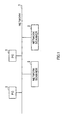
- FIG. 1 is a schematic view illustrating a network system where a network scanner operates according to one embodiment of the present invention.
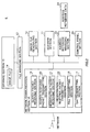
- FIG. 2 is a block diagram illustrating the function of the network scanner according to the above embodiment.
- a scanner section 11 scans a document to obtain an image signal.
- An image file generating section 12 generates an image file from the image signal output by the scanner section 11.
- a data format of the image file may be, for example, TIFF, GIF, JPEG and the like, and TIFF is used in this example.
- a file managing section 13 stores this image file 14 to a storage section 15.
- a network communication section 16 is connected to a network 1 by a network connection interference circuit (not shown) to perform communication with PC3 via network 1.
- an Lpd transmitting section 17 executes an Lpr/Lpd protocol between an Lpd receiving section 33 of PC3 to be described later and the Lpd transmitting section 17.
- a file transmitting section 18 executes the processing for transferring the image file 14 to PC3 using file managing section 13 through this Lpr/Lpd protocol procedure.
- a search packet receiving section 19 receives a search packet transmitted by PC3 to be described later.
- a search response packet transmitting section 20 transmits a search response packet, which is a response to the search packet received by the search packet receiving section 19, to PC3.
- a registration packet receiving section 21 receives a registration packet transmitted by PC3 to be described.
- a registration response packet transmitting section 22 transmits a registration response packet, serving as a response to the registration packet, to PC3.
- the functions of the respective sections of the forgoing network communication section 16 are implemented by software executed by CPU in this example, but they are not limited to this.
- An address notebook managing section 23 manages address notebook data 24 in which user terminal information is registered to be described later.
- a control panel 25 is used to read an IP address of transmission destination from the address notebook data 24 or to manually input an IP address in an unregistered case.
- FIG. 3 is a block diagram illustrating the function of a personal computer according to the above embodiment.
- PC 3 executes a network scanner controller application 31 that controls image scanning processing using the network scanner 2.
- a network communication section 32 performs communication with the foregoing network scanner 2.
- an Lpd receiving section 33 executes an Lpr/Lpd protocol between the Lpd transmitting section 17 of the foregoing network scanner 2 and the Lpd receiving section 33.
- a file receiving section 34 executes processing for receiving the image file from the network scanner 2 through this Lpr/Lpd protocol procedure.
- a search packet transmitting section 35 transmits a search packet on the network 1.
- a search response packet receiving section 36 receives a search response packet responded to this search packet.
- An image file storage processing section 39 stores the image file 14 received by the file receiving section 34 to the storage section 15.
- the file managing section 13 manages the image file stored to the storage section 15.
- a registration packet transmitting section 37 generates a registration packet from user terminal information 41 managed by a user terminal information managing section 40, and transmits the generated registration packet to the network scanner 2.
- a registration response packet receiving section 38 receives a registration response packet responded to the registration packet.
- An external application managing section 42 manages an external application 43, which is executed by PC3.
- This external application 43 includes an image viewer such as TIFF viewer, Adobe Photoshop (trademark of Adobe Corporation) and an image edit application.
- Lpr/Lpd protocol used in communication between the network scanner 2 and PC3 is a communication protocol, which is used to transmit/receive print data between hosts using UNIX as OS.
- the host which wishes to receive print service, outputs a request to a line printer daemon (Lpd), which is executed on a certain host.
- the daemon which has received the request, accepts it as a job, and queues it to perform processing.
- FIG. 4 is a sequence view illustrating an image file transfer carried out between the network scanner and the personal computer according to the above embodiment.
- the sender's network scanner 2 transmits a command "Received Job” instructing the reception of job to PC3 (ST401).
- PC3 sends back ACK to the network scanner 2 (ST402)
- the sender's network 2 transmits a sub-command "Receive control file” instructing the reception of control file to PC3 (ST403).
- This sub-command includes the size of control file and the name of control file name.
- control file includes a user name, a file name of image file, and the like.
- the network scanner 2 transmits a sub-command "Receive data file" representing the transmission of image file to PC3 (ST407).
- the network scanner 2 transmits an image file (TIFF file) to PC3 (ST409). If the reception of image file is completed, PC3 sends back ACK to the network scanner 2 (ST410).
- the transmission/reception of command, sub-command, control file and data file is carried out on not a packet-by-packet basis but a stream-by-stream basis.
- connection between the network scanner 2 and PC3 is established and then communication is carried out.
- Such a communication protocol is referred to as a connection type communication protocol, and an ftp protocol can be used in addition thereto.
- the network scanner 2 in order to perform data transmission to PC3 from the network scanner 2, the network scanner 2 must know the IP address of PC3 at the transmitting time.
- the network scanner 2 in order to register the IP address to address notebook data 24 together with the user name, the network scanner 2 must obtain the IP address and other relevant information (hereinafter referred to as user terminal information).
- FIG. 5 is a flowchart illustrating a user terminal information registration operation carried out between the network scanner and the personal computer according to the above embodiment.
- the search packet receiving section 19 monitors a packet with a specific port number on the network 1 (ST502).
- PC3 when PC3 is started up (ST503), PC3 detects the startup of network scanner controller application 31 or the reception of search start action (instruction of user registration) (ST504), and the search of the network scanner 2 on the network 1 is carried out in the following manner.
- the search packet transmitting section 35 broadcasts the search packet on the network 1 (ST505) and waits for the response (ST506).
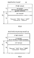
- FIG. 6 is a view showing a frame format of a search packet according to the above embodiment.
- a UDP packet is used as a search packet 60.
- a broadcast address for example, 255.255.255.255
- IP address of PC3 is specified in a sender address field.
- an UDP header 63 which is positioned at the top of an IP data field 62, the same port number that the search packet receiving section 19 of the network scanner 2 monitors is specified as a destination port number.
- an UDP data field 64 includes various kinds of information indicating that this packet is a search packet. Namely, the UDP data field 64 includes information "Discovery” indicting that this packet relates to an automatic registration of user terminal information, information "REQ” indicating that this packet relates to a processing request, and information "Group” indicating a group name to which the sender of the packet belongs.
- UDP protocol is a connectionless type communication protocol that does not have to establish the connection unlike the TPC protocol, it is suitable for searching the network scanner 2.
- the search packet receiving section 19 of the network scanner 2 receives the search packet 60, recognizes information "Group", and determines whether or not this is the group name to which a response should be given (507). For example, if the group name matches the name of a group to which the search packet receiving section 19 belongs, the search packet receiving section 19 determines that a response should be given. If it does not match, the search packet receiving section 19 determines that a response should not be given. In the case where it is determined that a response should not be given, the network scanner returns to a search packet waiting state without giving any response (ST508). On the other hand, in the case where it is determined that a response should be given, the search response packet transmitting section 20 sends back the search response packet to PC3 (ST509). In the case where PC3 transmits the search packet 60 including no information "Group", the network scanner 2 determines that this is the search from the other group and gives a response without fail.
- FIG. 7 is a view showing a frame format of a search response packet according to the above embodiment.
- a UDP packet is used as this search response packet 70.
- a sender of the search packet 60 that is, an IP address of PC3(hereinafter referred to as PC. IP address) is specified in a destination address field and an IP address of the network scanner 2 is specified in a sender address field.
- an UDP header 73 which is positioned at the top of an IP data field 72, the same port number that the search response packet receiving section 36 of PC 3 monitors is specified as a destination port number.
- an UDP data field 74 includes various kinds of information indicating that this packet is a search response packet. Namely, at the search packet 60 shown in FIG. 6, information "ACK" indicating that the packet relates to a processing response is used in place of information "REQ” indicating that the packet relates to a processing request.
- the registration packet transmitting section 37 of PC3 transmits the registration packet to the network scanner 2.
- FIG. 8 is a view showing a frame format of a registration packet according to the above embodiment.
- a UDP packet is used as this registration packet 80.
- the IP address of the network scanner 2 that has sent back the search response packet 70 is specified in the destination address field.
- an IP address of PC3 is specified in the sender address field.
- an UDP header 83 which is positioned at the top of an IP data field 82, the same port number that the registration packet receiving section 21 of the network scanner 2 monitors is specified as a destination port number.
- an UDP data field 84 includes information "USER” indicative of a user name, information “Lease period” indicative of effective time (lease period) of user terminal information (particularly, IP address) and information "Password” indicative of a password specified by the user, in addition to information "Discovery”, "REQ” and "Group.”
- the address notebook managing section 23 extracts user terminal information from the registration packet 80 (ST511), and registers it to address notebook data 24 (ST512). Thereafter, the registration response packet transmitting section 22 transmits a registration response packet 90 to PC3 to inform PC3 that registration has completed (ST513).
- FIG. 9 is a view showing a frame format of a registration response packet according to the above embodiment.
- a UDP packet is used as this registration packet 90.
- a sender of the registration packet 80 that is, a PC.
- IP address is specified in the destination address field.
- an IP address of the network scanner 2 is specified in the sender address field.
- an UDP header 93 which is positioned at the top of an IP data field 92, the same port number that the registration response packet receiving section 38 of PC3 monitors is specified as a destination port number.
- an UDP data field 94 includes various kinds of information indicating that this packet is a registration response packet. Namely, at the registration packet 80 shown in FIG. 8, information "AKC” indicating that the packet relates to a processing response is used in place of information "REQ” indicating that the packet relates to a processing request.
- FIG. 10 is a flowchart illustrating steps for search processing of the network scanner by the personal computer according to the above embodiment.
- PC3 resets a search retransmission counter to zero (ST1001).
- PC3 broadcasts the search packet 60 on the network 1.
- PC 3 obtains transmission start time from a built-in timer of PC3 (ST1004).
- PC 3 determines whether or not current time (obtained from the built-in timer) is greater than the sum of transmission start time and a total amount of search response waiting time, that is, whether or not a predetermined total amount of search response waiting time has elapsed since broadcast transmission (ST1003) (ST1005).
- PC3 waits for the reception of search response until predetermined search response waiting time per one time elapses (ST1006).
- PC3 determines whether or not the search response packet 70 is received while waiting for the reception (ST1007).
- PC3 determines whether or not the received search response packet 70 is one that responds to the search packet 60 transmitted by PC3 (ST1008). This can be carried out by, for example, determining whether information of the UDP data field of the search response packet 70 is "Discovery" and the processing response is "ACK" or not.
- the IP address of network scanner 2 obtained from the search response packet 70 is registered to a response table (ST1009). After registration, processing goes back to ST1005.
- the received search response packet 70 is not one that responds to the search packet 60 transmitted by PC3 so that the search response packet 70 is abandoned and processing goes back to ST1005.
- PC3 determines whether or not the response table is empty (ST1010).
- the search packet 60 disappears on the network 1 for some reason and does not reach any network scanner 2 in some cases .
- the search retransmission counter is incremented by one (ST1011) and processing goes back to ST1002.
- processing in ST1003 to ST1009 is repeated. Accordingly, the retransmission of search packet 60 is carried out up to the maximum number of the search retransmission times.
- step ST1010 determines whether the search packet 60 is effectively transmitted, so that processing goes back to ST1005. Then, processing in ST1006 to ST1009 is repeated, so that PC3 waits for a response from the network scanner 2 until time that has elapsed since broadcast transmission (ST1003) reaches the total amount of search response waiting time.
- PC3 can search all available network scanners 2, which exist on the network 1, and obtain the corresponding IP addresses. Moreover, PC3 can search the network scanners 2 without fail even if the search packet disappears or delay in response time of network scanner 2 occurs.
- FIG. 11 is a flowchart illustrating steps for responding to the search from the personal computer by the network scanner according to the above embodiment.
- the network scanner 2 normally waits for the reception of search packet 60 from PC3 (ST1101). If the network scanner 2 receives the packet (ST1102), the network scanner 2 checks whether or not the received packet is search packet 60 (ST1103). If "Discovery" and "REQ" are included in the received packet as illustrated in FIG. 6, the network scanner 2 determines that the received packet is search packet 60.
- the network scanner 2 recognizes the group name of PC3 from information "Group" included in the search packet 60, and checks whether or not the group name matches the name of the group to which the network scanner 2 belongs (ST1104). If they match each other (YES), the network scanner 2 prepares the search response packet 70 including the IP address of the network scanner 2 and transmits it to PC3 (ST1105). If they do not match (NO), the network scanner 2 checks whether or not the search packet 60 includes information "Group" (ST1106). If the search packet does not include information "Group” (YES), the network scanner 2 determines that this is the search from the other group, and processing moves to ST1105 to transmit the search response packet 70. While, if the result is NO, the network scanner 2 abandons the packet and goes back to ST1101. In this way, the network scanner 2 responds to the search from PC3 and notifies PC3 of the IP address of the network scanner 2.
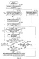
- FIG. 12 is a flowchart illustrating steps for registering user terminal information to the network scanner in the personal computer according to the above embodiment.
- PC3 determines whether or not a response table is empty (ST1201). If it is empty (YES), PC3 ends the registration steps (ST1202). If it is not empty (NO), PC3 extracts the IP address (registration destination) of a first network scanner 2 from the top of the response table (ST1203). Next, PC3 resets a registration retransmission counter to zero (ST1204). After that, PC3 determines whether or not the registration retransmission counter exceeds a maximum number of registration retransmission times (ST1205). If the determination result is NO, PC3 prepares a registration packet 80 shown in FIG. 8 and transmits it to the network scanner 2(ST1206).
- the PC3 After transmitting the registration packet 80, the PC3 obtains transmission start time from the built-in timer of PC3 (ST1207). Next, PC 3 determines whether or not current time is greater than the sum of transmission start time and a total amount of registration response waiting time, that is, whether or not a predetermined total amount of registration response waiting time has elapsed since the start of transmission (ST1208).
- PC3 waits for a registration response packet 90 from the network scanner 2 until predetermined registration response waiting time per one time elapses (ST1209). After that, PC3 determines whether or not the registration response packet 90 is received (ST1210). If the determination result is "YES” , PC3 determines whether or not the registration response packet 90 is one that responds to the registration packet 80 transmitted by PC3 (ST1211). If the determination result is "YES” in ST1211, PC3 extract the IP address of network scanner 2, which has responded, from the registration response packet 90, and registers it to a registration destination table (ST1212). After deleting the registration destination from the registration destination table (ST1213), processing goes back to ST1201 to carry out steps for registering user terminal information to a next registration destination.
- FIG. 13 is a flowchart illustrating steps for responding to the user registration from the personal computer by the network scanner according to the above embodiment.
- the network scanner 2 normally waits for the reception of registration packet 80 from PC3 (ST1301). If the network scanner 2 receives the packet (ST1302) the network scanner 2 checks whether the received packet is the registration packet 80 or not (ST1303). If “Discovery”, "REQ” and "USER" are included in the received packet as illustrated in FIG. 8, the network scanner 2 determines that the received packet is the registration packet 80.
- the network scanner 2 recognizes the group name of PC3 from information "Group" included in the registration packet 80, and checks whether or not the group name matches the name of the group to which the network scanner 2 belongs (ST1304). If they match each other (YES), processing goes to ST1305. While, if they do not match (NO), the network scanner 2 checks whether or not information "Group” is included in the registration packet 80 in ST1306. If it is not included therein (YES), the network scanner 2 determines that this is the request for registering user terminal information from the other the group, and processing moves to ST1305.
- the network scanner 2 searches address notebook data 24 using information "USER" included in the registration packet 80, and checks whether or not the same user name is already registered. If the result is "NO", the network scanner 2 newly registers user terminal information such as a user name extracted from the registration packet 80, PC. IP address, group name, password and the like to address notebook data 24 (ST1307).
- the network scanner 2 checks whether or not the user name and password, which are already registered as user terminal information, match the user name and password, which are indicated by each of information "USER" and "Group” included in the registration packet 80 (ST1308). If the result is "YES” in ST1308, the network scanner 2 determines that both are the same and overwrites the existing user terminal information onto address notebook data 24 using user terminal information extracted from the registration packet 80 (ST1309). On the other hand, if the result is "NO”, the network scanner 2 determines that both are not the same and newly registers user terminal information to address notebook data 24 (ST1307). This prevents user terminal information from being erroneously overwritten.
- the network scanner 2 prepares the registration response packet 90 and transmits it to PC3 (ST1310), and returns to a reception waiting state for registration packet 80 (ST1301).
- the network scanner 2 extracts user terminal information upon receiving the registration packet 80 from PC3, making it possible to newly register the extracted user terminal information to address notebook data or update it.
- the following will explain the steps in which the network scanner 2 scans a document and transmits digital image data to PC3 using user terminal information registered to the network scanner 2 from PC3 as mentioned above.
- FIG. 14 is a flowchart illustrating steps for transmitting digital image data between the network scanner and the personal computer according to the above embodiment.
- the network scanner 2 selects whether or not the address notebook is used in order to specify a transmission destination of digital image data (ST1401).
- the network scanner 2 carries out this selection by selecting an address notebook menu from menus.
- the network scanner 2 displays the user name registered to address notebook data 24 on an LCD provided at the control panel 25, and instructs the user to select the user name (ST1402). If the user name is selected, the IP address of PC3 registered to address notebook data 24 to be associated with this user name is called up and specified as a destination.
- the network scanner 2 determines whether or not the password is registered to be associated with the specified IP address (ST1403). If the result is YES, the network scanner 2 displays a message of a request for inputting a password on LCD, and waits for the entry of password (ST1404). If the password is input, the input password is checked against the password registered to address notebook data 24 (ST1405). If both match each other (YES), processing goes to ST1406. If both do not match each other (NO), processing is ended. If no password is registered in ST1403 (NO), processing also goes to ST1406.
- the scanner section 11 of network scanner 2 scans the document and obtains image information.
- the image file generating section 12 converts image information to an image file with a TIFF format (ST1408).
- the network scanner 2 transfers the image file to PC3 as a specified destination according to the foregoing Lpr/Lpt protocol (ST1409).
- the image file storage processing section 39 stores the image file to the storage section 15 (ST1410).
- PC3 merely starts up the network scanner controller application 31 or the user carries out the search starting action, so that the user can automatically register user terminal information including the IP address of PC3 to the network scanner 2 without examining the IP addresses of PC3 and network scanner 2.
- This makes it possible for the user to easily register user terminal information of PC3 to the network scanner 2 without fail even if the user has a poor knowledge of the PC or network.
- the IP address of destination is called up from address notebook data 24 of the network scanner 2 to instruct the scanner section 11 to scan the document, so that image information can be transmitted to PC3 and stored. This makes it possible to save time and effort to input the IP address at a document scanning time.
- information "Password” is included in user terminal information to be included in the registration packet 80.
- the IP address and password are registered to address notebook data 24 of the network scanner 2 to be associated with each other.
- the checking of passwords is performed (ST1403 to ST1405) before the start of scanning the document (ST1406) as illustrated in FIG. 14, and the scanning of document is allowed only when the passwords match each other. This makes it possible to prohibit the image file to be freely transmitted to PC3.
- information "USER" is included in user terminal information of registration packet 80 and the IP address and user name are registered to address notebook data 24 of the network scanner 2 to be associated with each other. For this reason, the user can call up the IP address from address notebook data 24 based on the user name in place of the IP address, which is identified with difficulty at the document scanning time, so that the operation can be easily carried out.
- information"Group is included in the search packet 60 and registration packet 80 so that the response and registration are carried out only when the network scanner 2 and PC3 belong to the same group. Resultantly, for example, a plurality of network scanners 2 is provided at one office so that these network scanners 2 can be selectively used according to the group to which the user belongs. Also, this eliminates the user having to have consciousness about this selective use at the time of registering user information.
- This invention may be conveniently implemented using a conventional general purpose digital computer or microprocessor programmed according to the teachings of the present specification, as will be apparent to those skilled in the computer art.
- Appropriate software coding can readily be prepared by skilled in programmers based on the teachings of the present disclosure, as will be apparent to those skilled in the software art.
- the invention may also be implemented by the preparation of application specific integrated circuits or by interconnecting an appropriate network of conventional component circuits, as will be readily apparent to those skilled in the art.
- the present invention includes a computer program product which is a storage medium including instructions which can be used to program a computer to perform a process of the invention.
- the storage medium can include, but is not limited to, any type of disk including floppy disks, optical discs, CD-ROMs, and magneto-optical disks, ROMs, RAMs, EPROMs, EEPROMs, magnetic or optical cards, or any type of media suitable for storing electronic instructions.
- the user terminal apparatus broadcasts the search signal, recognizes the IP address of the scanner apparatus from the response signal, which responds to the search signal and which is transmitted from the scanner apparatus. Then, the user terminal apparatus transmits user terminal information including the IP address of user terminal apparatus to the IP address of the scanner apparatus to the scanner apparatus, whereby making it possible to instruct the scanner apparatus to register user terminal information. Resultantly, the user can easily register user terminal information to the scanner apparatus without fail even if the user has a poor knowledge of IT (Information Technology).
- IT Information Technology
- the IP address of destination is called up from memory of the scanner apparatus to instruct the scanner apparatus to scan the document, so that image information can be transmitted to the user terminal apparatus to which this IP address is assigned and can be stored. This makes it possible to save time and effort to input the IP address at a document scanning time.
Landscapes
- Engineering & Computer Science (AREA)
- General Engineering & Computer Science (AREA)
- Multimedia (AREA)
- Signal Processing (AREA)
- Computing Systems (AREA)
- Facsimiles In General (AREA)
- Facsimile Transmission Control (AREA)
- Mobile Radio Communication Systems (AREA)
Applications Claiming Priority (2)
| Application Number | Priority Date | Filing Date | Title |
|---|---|---|---|
| JP2001026646A JP3450830B2 (ja) | 2001-02-02 | 2001-02-02 | 画情報送信システム、スキャナ装置およびユーザ端末装置、並びにスキャナ装置へのユーザ端末情報登録方法 |
| JP2001026646 | 2001-02-02 |
Publications (3)
| Publication Number | Publication Date |
|---|---|
| EP1229716A2 true EP1229716A2 (de) | 2002-08-07 |
| EP1229716A3 EP1229716A3 (de) | 2005-01-26 |
| EP1229716B1 EP1229716B1 (de) | 2013-10-23 |
Family
ID=18891429
Family Applications (1)
| Application Number | Title | Priority Date | Filing Date |
|---|---|---|---|
| EP02002403.0A Expired - Lifetime EP1229716B1 (de) | 2001-02-02 | 2002-01-31 | Bildinformationsübertragungssystem, Abtastgerät und Benutzerendgerät und Verfahren zum Registrieren von Benutzerendgerätinformation an einem Abtastgerät |
Country Status (3)
| Country | Link |
|---|---|
| US (1) | US7155522B2 (de) |
| EP (1) | EP1229716B1 (de) |
| JP (1) | JP3450830B2 (de) |
Cited By (1)
| Publication number | Priority date | Publication date | Assignee | Title |
|---|---|---|---|---|
| EP1530128A3 (de) * | 2003-11-05 | 2005-08-17 | Sony Corporation | Methode und System zur Installation von Software in einem Netzwerk |
Families Citing this family (23)
| Publication number | Priority date | Publication date | Assignee | Title |
|---|---|---|---|---|
| KR100453052B1 (ko) * | 2002-06-07 | 2004-10-15 | 삼성전자주식회사 | 전송 패킷을 이용하여 다기능을 수행하기 위한 통신 방법 및 장치 |
| US7257705B2 (en) * | 2002-11-18 | 2007-08-14 | Sparta Systems, Inc. | Method for preserving changes made during a migration of a system's configuration to a second configuration |
| US7480287B2 (en) * | 2002-11-19 | 2009-01-20 | Murata Kikai Kabushiki Kaisha | Communication terminal device, communication method and electronic mail server |
| US7313698B2 (en) | 2002-12-27 | 2007-12-25 | Brother Kogyo Kabushiki Kaisha | Image data processing system, image data generating apparatus, terminal equipment and program product |
| KR100580173B1 (ko) * | 2003-07-15 | 2006-05-15 | 삼성전자주식회사 | 네트워크 스캐닝 방법 및 장치와 이를 위한 패킷 포맷 |
| US20050097337A1 (en) * | 2003-11-03 | 2005-05-05 | Robert Sesek | Systems and methods for providing recipient-end security for transmitted data |
| WO2005066823A1 (ja) * | 2004-01-07 | 2005-07-21 | Matsushita Electric Industrial Co., Ltd. | サーバ、端末装置、機器登録システム、登録方法、登録プログラム、及び、記録媒体 |
| JP2006033086A (ja) | 2004-07-12 | 2006-02-02 | Canon Inc | 画像処理システム、情報処理装置、画像処理装置、それらの制御方法、それらの制御プログラム並びに、その制御プログラムを格納した記憶媒体 |
| KR100565081B1 (ko) * | 2004-09-20 | 2006-03-30 | 삼성전자주식회사 | 방화벽을 통과하는 네트워크 스캔 시스템 및 네트워크스캔 시스템 구성 방법 |
| JP2006339904A (ja) * | 2005-05-31 | 2006-12-14 | Brother Ind Ltd | 画像読取システム、画像読取装置の制御プログラム、端末装置の制御プログラム、および画像読取装置 |
| JP2007189503A (ja) * | 2006-01-13 | 2007-07-26 | Matsushita Electric Ind Co Ltd | 端末装置及びプログラム |
| JP4895763B2 (ja) * | 2006-11-06 | 2012-03-14 | 株式会社リコー | 画像入力装置、データの送信先保存方法、データの送信先保存プログラム及びその記憶媒体 |
| JP4895864B2 (ja) | 2007-02-28 | 2012-03-14 | 株式会社リコー | 画像入力装置、画像入力装置の情報登録方法、プログラム及びその記憶媒体 |
| JP5091791B2 (ja) | 2008-07-22 | 2012-12-05 | 京セラドキュメントソリューションズ株式会社 | 画像形成システム、画像形成装置およびコンピュータプログラム |
| JP5546189B2 (ja) * | 2009-09-18 | 2014-07-09 | キヤノン株式会社 | 画像形成装置、画像形成装置の制御方法及びプログラム |
| JP5515827B2 (ja) * | 2010-02-16 | 2014-06-11 | 株式会社リコー | 画像形成装置、表示管理装置、画像管理システム及び制御プログラム |
| JP5287812B2 (ja) * | 2010-09-09 | 2013-09-11 | ブラザー工業株式会社 | デバイス |
| KR101929299B1 (ko) * | 2011-12-06 | 2019-03-13 | 삼성전자주식회사 | 이동통신 네트워크에서 요금 지불을 대행하는 인터넷 서비스 제공 방법 및 장치 |
| JP2015103975A (ja) | 2013-11-25 | 2015-06-04 | キヤノン株式会社 | 画像読取システム、画像読取装置、情報処理装置、それらの制御方法、及びプログラム |
| JP2015104880A (ja) * | 2013-11-29 | 2015-06-08 | 京セラドキュメントソリューションズ株式会社 | 周辺機器、端末、省電力制御システム、省電力制御方法、及び省電力制御プログラム |
| JP2016062232A (ja) * | 2014-09-17 | 2016-04-25 | 株式会社リコー | 情報処理システム、情報処理装置、プログラム及び情報処理方法 |
| US11164211B2 (en) * | 2014-10-07 | 2021-11-02 | Grandpad, Inc. | System and method for enabling efficient digital marketing on portable wireless devices for parties with low capabilities |
| JP2020108027A (ja) | 2018-12-27 | 2020-07-09 | シャープ株式会社 | 接続システム、制御方法、画像処理装置及び通信方法 |
Citations (3)
| Publication number | Priority date | Publication date | Assignee | Title |
|---|---|---|---|---|
| US5911044A (en) | 1996-11-08 | 1999-06-08 | Ricoh Company, Ltd. | Network image scanning system which transmits image information from a scanner over a network to a client computer |
| EP1001584A2 (de) | 1998-11-12 | 2000-05-17 | Ricoh Company, Ltd. | Verfahren und Vorrichtung zur automatischen Netzkonfiguration |
| JP2001026646A (ja) | 1999-07-14 | 2001-01-30 | Sumitomo Chem Co Ltd | プリント基板用多孔質フィルム、プリプレグおよびプリント回路積層板 |
Family Cites Families (21)
| Publication number | Priority date | Publication date | Assignee | Title |
|---|---|---|---|---|
| JP4035173B2 (ja) * | 1993-01-18 | 2008-01-16 | キヤノン株式会社 | 制御装置および制御方法 |
| JP3621180B2 (ja) | 1996-01-24 | 2005-02-16 | 株式会社リコー | ネットワークスキャナ装置 |
| JPH09233239A (ja) | 1996-02-21 | 1997-09-05 | Mitsubishi Electric Corp | ファクシミリ装置 |
| JP3140381B2 (ja) * | 1996-10-30 | 2001-03-05 | 松下電送システム株式会社 | データ通信装置 |
| US6052784A (en) * | 1997-10-14 | 2000-04-18 | Intel Corporation | Network discovery system and method |
| US6327613B1 (en) * | 1998-01-12 | 2001-12-04 | Adaptec, Inc. | Method and apparatus for sharing peripheral devices over a network |
| JPH11233239A (ja) | 1998-02-20 | 1999-08-27 | Jidosha Kiki Co Ltd | セラミックスヒーター又はセラミックスグロープラグ及びそれらの製造方法 |
| JPH11341065A (ja) | 1998-05-26 | 1999-12-10 | Sanyo Electric Co Ltd | ネットワーク通信の機器設定システムおよび機器設定方法 |
| US6839755B1 (en) * | 1998-09-30 | 2005-01-04 | Hewlett-Packard Development Company, L.P. | Network peripheral server discovery method |
| US6223223B1 (en) * | 1998-09-30 | 2001-04-24 | Hewlett-Packard Company | Network scanner contention handling method |
| US20010039587A1 (en) * | 1998-10-23 | 2001-11-08 | Stephen Uhler | Method and apparatus for accessing devices on a network |
| US6496859B2 (en) * | 1998-11-25 | 2002-12-17 | Xerox Corporation | System for network device location |
| US6167462A (en) * | 1998-12-11 | 2000-12-26 | Hewlett-Packard Company | Remote scanning through a computer system network |
| JP2000244694A (ja) | 1999-02-17 | 2000-09-08 | Canon Inc | 画像処理装置および画像処理方法 |
| JP2001028655A (ja) | 1999-07-14 | 2001-01-30 | Ricoh Co Ltd | 画像配信システム |
| US6502128B1 (en) * | 1999-10-01 | 2002-12-31 | Hewlett-Packard Company | Server and a method for communicating event messages from the server connected to a peripheral device and a client computer |
| JP2001111628A (ja) * | 1999-10-08 | 2001-04-20 | Matsushita Graphic Communication Systems Inc | 画像送信装置、画像受信装置およびそれらの方法 |
| JP3489513B2 (ja) * | 1999-12-08 | 2004-01-19 | 日本電気株式会社 | スキャナ装置 |
| JP3525842B2 (ja) * | 2000-02-01 | 2004-05-10 | 日本電気株式会社 | ネットワークスキャナ装置及びプログラムを記録した記録媒体 |
| US20020038372A1 (en) * | 2000-09-28 | 2002-03-28 | Takenori Idehara | Network device connecting system, data transmission device, data receiving device, and portable terminal |
| KR20020026745A (ko) * | 2000-10-02 | 2002-04-12 | 윤종용 | 인터넷을 기반으로 한 네트워크 시스템 및 그 통신방법 |
-
2001
- 2001-02-02 JP JP2001026646A patent/JP3450830B2/ja not_active Expired - Fee Related
-
2002
- 2002-01-29 US US10/057,912 patent/US7155522B2/en not_active Expired - Fee Related
- 2002-01-31 EP EP02002403.0A patent/EP1229716B1/de not_active Expired - Lifetime
Patent Citations (3)
| Publication number | Priority date | Publication date | Assignee | Title |
|---|---|---|---|---|
| US5911044A (en) | 1996-11-08 | 1999-06-08 | Ricoh Company, Ltd. | Network image scanning system which transmits image information from a scanner over a network to a client computer |
| EP1001584A2 (de) | 1998-11-12 | 2000-05-17 | Ricoh Company, Ltd. | Verfahren und Vorrichtung zur automatischen Netzkonfiguration |
| JP2001026646A (ja) | 1999-07-14 | 2001-01-30 | Sumitomo Chem Co Ltd | プリント基板用多孔質フィルム、プリプレグおよびプリント回路積層板 |
Cited By (2)
| Publication number | Priority date | Publication date | Assignee | Title |
|---|---|---|---|---|
| EP1530128A3 (de) * | 2003-11-05 | 2005-08-17 | Sony Corporation | Methode und System zur Installation von Software in einem Netzwerk |
| EP1734448A3 (de) * | 2003-11-05 | 2007-01-17 | Sony Corporation | Installationsverfahren, Netzwerkgerät, Identifikationsinformationen, Kommunikationsverfahren, Informationsverarbeitungsverfahren, Verfahren zum Erhalt von Verbindungsinformation, Verfahren zur Anzeige von Verbindungsinformationen, Aufzeichnungsmedium und Programm |
Also Published As
| Publication number | Publication date |
|---|---|
| EP1229716A3 (de) | 2005-01-26 |
| JP2002232637A (ja) | 2002-08-16 |
| US7155522B2 (en) | 2006-12-26 |
| EP1229716B1 (de) | 2013-10-23 |
| JP3450830B2 (ja) | 2003-09-29 |
| US20020107937A1 (en) | 2002-08-08 |
Similar Documents
| Publication | Publication Date | Title |
|---|---|---|
| EP1229716B1 (de) | Bildinformationsübertragungssystem, Abtastgerät und Benutzerendgerät und Verfahren zum Registrieren von Benutzerendgerätinformation an einem Abtastgerät | |
| JP3153781B2 (ja) | 中継通信装置及び中継通信方法 | |
| US9350885B2 (en) | Image reading device and image processing method utilizing the same | |
| EP1091561B1 (de) | Gerät und Verfahren zum Senden und Empfangen von Bildern | |
| US20070146802A1 (en) | Communication apparatus, communication method, communication system, and storage medium | |
| EP1229717B1 (de) | Bildinformationsübertragungssystem, Abtastgerät und Benutzerendgerät | |
| US20140002857A1 (en) | Document scanning method and computer program for controlling scanning apparatus | |
| JP5359700B2 (ja) | 画像形成装置、画像形成装置利用システム、画像形成方法 | |
| KR101391109B1 (ko) | 화상 판독 장치, 방법 및 프로그램을 기억한 기억 매체 | |
| US20090033985A1 (en) | Mobile device, printer server and private network system, and methods to receive fax data thereby | |
| KR101758854B1 (ko) | 스캐닝장치, 이에 연결된 모바일장치 및 그 스캔작업수행방법 | |
| US7564577B2 (en) | Fax gateway, fax machine, and fax transmission system | |
| JP2000059553A (ja) | 画像入力装置及びその制御方法 | |
| JP5783001B2 (ja) | 通信システム、通信端末装置、サーバ装置及びクラウド転送用ボックスの設定方法 | |
| US10624139B2 (en) | Communication device and storage medium suitable for connection to wireless LAN (local area network) | |
| JP3675624B2 (ja) | ネットワークスキャナ | |
| JP3437533B2 (ja) | ネットワークファクシミリ装置および回線選択方法 | |
| JPH1169051A (ja) | ファクシミリ装置 | |
| JP4722336B2 (ja) | データ送信装置、データ送信先登録方法ならびにデータ送信先登録プログラムおよびこれを記録したコンピュータ読み取り可能な記録媒体 | |
| KR101499553B1 (ko) | 스캔 데이터 처리 방법 및 장치 | |
| JP5338539B2 (ja) | 画像形成装置、画像形成装置利用システム、画像データ生成方法 | |
| JP4535681B2 (ja) | ネットワークファクシミリ装置 | |
| JP2019071508A (ja) | 通信装置、その制御方法、及びプログラム | |
| JP4535688B2 (ja) | ネットワークファクシミリ装置 | |
| US20210337081A1 (en) | Processing facsimile in cloud server |
Legal Events
| Date | Code | Title | Description |
|---|---|---|---|
| PUAI | Public reference made under article 153(3) epc to a published international application that has entered the european phase |
Free format text: ORIGINAL CODE: 0009012 |
|
| AK | Designated contracting states |
Kind code of ref document: A2 Designated state(s): AT BE CH CY DE DK ES FI FR GB GR IE IT LI LU MC NL PT SE TR |
|
| AX | Request for extension of the european patent |
Free format text: AL;LT;LV;MK;RO;SI |
|
| 17P | Request for examination filed |
Effective date: 20030910 |
|
| RAP1 | Party data changed (applicant data changed or rights of an application transferred) |
Owner name: PANASONIC COMMUNICATIONS CO., LTD. |
|
| PUAL | Search report despatched |
Free format text: ORIGINAL CODE: 0009013 |
|
| AK | Designated contracting states |
Kind code of ref document: A3 Designated state(s): AT BE CH CY DE DK ES FI FR GB GR IE IT LI LU MC NL PT SE TR |
|
| AX | Request for extension of the european patent |
Extension state: AL LT LV MK RO SI |
|
| AKX | Designation fees paid |
Designated state(s): DE FR GB |
|
| RAP1 | Party data changed (applicant data changed or rights of an application transferred) |
Owner name: PANASONIC SYSTEM NETWORKS CO., LTD. |
|
| 17Q | First examination report despatched |
Effective date: 20110815 |
|
| GRAP | Despatch of communication of intention to grant a patent |
Free format text: ORIGINAL CODE: EPIDOSNIGR1 |
|
| INTG | Intention to grant announced |
Effective date: 20130524 |
|
| GRAS | Grant fee paid |
Free format text: ORIGINAL CODE: EPIDOSNIGR3 |
|
| GRAA | (expected) grant |
Free format text: ORIGINAL CODE: 0009210 |
|
| AK | Designated contracting states |
Kind code of ref document: B1 Designated state(s): DE FR GB |
|
| REG | Reference to a national code |
Ref country code: GB Ref legal event code: FG4D |
|
| REG | Reference to a national code |
Ref country code: DE Ref legal event code: R096 Ref document number: 60245664 Country of ref document: DE Effective date: 20131224 |
|
| PGFP | Annual fee paid to national office [announced via postgrant information from national office to epo] |
Ref country code: DE Payment date: 20140129 Year of fee payment: 13 |
|
| PGFP | Annual fee paid to national office [announced via postgrant information from national office to epo] |
Ref country code: FR Payment date: 20140108 Year of fee payment: 13 |
|
| PGFP | Annual fee paid to national office [announced via postgrant information from national office to epo] |
Ref country code: GB Payment date: 20140120 Year of fee payment: 13 |
|
| REG | Reference to a national code |
Ref country code: DE Ref legal event code: R097 Ref document number: 60245664 Country of ref document: DE |
|
| PLBE | No opposition filed within time limit |
Free format text: ORIGINAL CODE: 0009261 |
|
| STAA | Information on the status of an ep patent application or granted ep patent |
Free format text: STATUS: NO OPPOSITION FILED WITHIN TIME LIMIT |
|
| 26N | No opposition filed |
Effective date: 20140724 |
|
| REG | Reference to a national code |
Ref country code: DE Ref legal event code: R097 Ref document number: 60245664 Country of ref document: DE Effective date: 20140724 |
|
| REG | Reference to a national code |
Ref country code: DE Ref legal event code: R119 Ref document number: 60245664 Country of ref document: DE |
|
| GBPC | Gb: european patent ceased through non-payment of renewal fee |
Effective date: 20150131 |
|
| PG25 | Lapsed in a contracting state [announced via postgrant information from national office to epo] |
Ref country code: GB Free format text: LAPSE BECAUSE OF NON-PAYMENT OF DUE FEES Effective date: 20150131 Ref country code: DE Free format text: LAPSE BECAUSE OF NON-PAYMENT OF DUE FEES Effective date: 20150801 |
|
| REG | Reference to a national code |
Ref country code: FR Ref legal event code: ST Effective date: 20150930 |
|
| PG25 | Lapsed in a contracting state [announced via postgrant information from national office to epo] |
Ref country code: FR Free format text: LAPSE BECAUSE OF NON-PAYMENT OF DUE FEES Effective date: 20150202 |