EP1231085B1 - Système de suspension hydropneumatique - Google Patents
Système de suspension hydropneumatique Download PDFInfo
- Publication number
- EP1231085B1 EP1231085B1 EP02394020A EP02394020A EP1231085B1 EP 1231085 B1 EP1231085 B1 EP 1231085B1 EP 02394020 A EP02394020 A EP 02394020A EP 02394020 A EP02394020 A EP 02394020A EP 1231085 B1 EP1231085 B1 EP 1231085B1
- Authority
- EP
- European Patent Office
- Prior art keywords
- hydro
- spring
- pneumatic
- pneumatic spring
- suspension system
- Prior art date
- Legal status (The legal status is an assumption and is not a legal conclusion. Google has not performed a legal analysis and makes no representation as to the accuracy of the status listed.)
- Expired - Lifetime
Links
- 239000000725 suspension Substances 0.000 title claims abstract description 49
- 238000013459 approach Methods 0.000 claims abstract description 9
- 239000012528 membrane Substances 0.000 claims description 8
- 238000013016 damping Methods 0.000 claims description 5
- 239000011343 solid material Substances 0.000 claims description 2
- 238000010276 construction Methods 0.000 description 2
- 230000007423 decrease Effects 0.000 description 2
- 230000000694 effects Effects 0.000 description 2
- 230000003068 static effect Effects 0.000 description 2
- 230000002411 adverse Effects 0.000 description 1
- 230000006835 compression Effects 0.000 description 1
- 238000007906 compression Methods 0.000 description 1
- 239000012530 fluid Substances 0.000 description 1
- 239000002184 metal Substances 0.000 description 1
Images




Classifications
-
- B—PERFORMING OPERATIONS; TRANSPORTING
- B60—VEHICLES IN GENERAL
- B60G—VEHICLE SUSPENSION ARRANGEMENTS
- B60G11/00—Resilient suspensions characterised by arrangement, location or kind of springs
- B60G11/32—Resilient suspensions characterised by arrangement, location or kind of springs having springs of different kinds
- B60G11/48—Resilient suspensions characterised by arrangement, location or kind of springs having springs of different kinds not including leaf springs
- B60G11/56—Resilient suspensions characterised by arrangement, location or kind of springs having springs of different kinds not including leaf springs having helical, spiral or coil springs, and also fluid springs
- B60G11/58—Resilient suspensions characterised by arrangement, location or kind of springs having springs of different kinds not including leaf springs having helical, spiral or coil springs, and also fluid springs arranged coaxially
-
- B—PERFORMING OPERATIONS; TRANSPORTING
- B60—VEHICLES IN GENERAL
- B60G—VEHICLE SUSPENSION ARRANGEMENTS
- B60G11/00—Resilient suspensions characterised by arrangement, location or kind of springs
- B60G11/32—Resilient suspensions characterised by arrangement, location or kind of springs having springs of different kinds
- B60G11/48—Resilient suspensions characterised by arrangement, location or kind of springs having springs of different kinds not including leaf springs
- B60G11/56—Resilient suspensions characterised by arrangement, location or kind of springs having springs of different kinds not including leaf springs having helical, spiral or coil springs, and also fluid springs
-
- B—PERFORMING OPERATIONS; TRANSPORTING
- B60—VEHICLES IN GENERAL
- B60G—VEHICLE SUSPENSION ARRANGEMENTS
- B60G15/00—Resilient suspensions characterised by arrangement, location or type of combined spring and vibration damper, e.g. telescopic type
- B60G15/02—Resilient suspensions characterised by arrangement, location or type of combined spring and vibration damper, e.g. telescopic type having mechanical spring
- B60G15/06—Resilient suspensions characterised by arrangement, location or type of combined spring and vibration damper, e.g. telescopic type having mechanical spring and fluid damper
- B60G15/061—Resilient suspensions characterised by arrangement, location or type of combined spring and vibration damper, e.g. telescopic type having mechanical spring and fluid damper with a coil spring being mounted inside the damper
-
- B—PERFORMING OPERATIONS; TRANSPORTING
- B60—VEHICLES IN GENERAL
- B60G—VEHICLE SUSPENSION ARRANGEMENTS
- B60G15/00—Resilient suspensions characterised by arrangement, location or type of combined spring and vibration damper, e.g. telescopic type
- B60G15/08—Resilient suspensions characterised by arrangement, location or type of combined spring and vibration damper, e.g. telescopic type having fluid spring
- B60G15/12—Resilient suspensions characterised by arrangement, location or type of combined spring and vibration damper, e.g. telescopic type having fluid spring and fluid damper
-
- B—PERFORMING OPERATIONS; TRANSPORTING
- B60—VEHICLES IN GENERAL
- B60G—VEHICLE SUSPENSION ARRANGEMENTS
- B60G17/00—Resilient suspensions having means for adjusting the spring or vibration-damper characteristics, for regulating the distance between a supporting surface and a sprung part of vehicle or for locking suspension during use to meet varying vehicular or surface conditions, e.g. due to speed or load
- B60G17/02—Spring characteristics, e.g. mechanical springs and mechanical adjusting means
- B60G17/04—Spring characteristics, e.g. mechanical springs and mechanical adjusting means fluid spring characteristics
-
- B—PERFORMING OPERATIONS; TRANSPORTING
- B60—VEHICLES IN GENERAL
- B60G—VEHICLE SUSPENSION ARRANGEMENTS
- B60G17/00—Resilient suspensions having means for adjusting the spring or vibration-damper characteristics, for regulating the distance between a supporting surface and a sprung part of vehicle or for locking suspension during use to meet varying vehicular or surface conditions, e.g. due to speed or load
- B60G17/02—Spring characteristics, e.g. mechanical springs and mechanical adjusting means
- B60G17/04—Spring characteristics, e.g. mechanical springs and mechanical adjusting means fluid spring characteristics
- B60G17/048—Spring characteristics, e.g. mechanical springs and mechanical adjusting means fluid spring characteristics with the regulating means inside the fluid springs
-
- F—MECHANICAL ENGINEERING; LIGHTING; HEATING; WEAPONS; BLASTING
- F16—ENGINEERING ELEMENTS AND UNITS; GENERAL MEASURES FOR PRODUCING AND MAINTAINING EFFECTIVE FUNCTIONING OF MACHINES OR INSTALLATIONS; THERMAL INSULATION IN GENERAL
- F16F—SPRINGS; SHOCK-ABSORBERS; MEANS FOR DAMPING VIBRATION
- F16F13/00—Units comprising springs of the non-fluid type as well as vibration-dampers, shock-absorbers, or fluid springs
- F16F13/002—Units comprising springs of the non-fluid type as well as vibration-dampers, shock-absorbers, or fluid springs comprising at least one fluid spring
-
- F—MECHANICAL ENGINEERING; LIGHTING; HEATING; WEAPONS; BLASTING
- F16—ENGINEERING ELEMENTS AND UNITS; GENERAL MEASURES FOR PRODUCING AND MAINTAINING EFFECTIVE FUNCTIONING OF MACHINES OR INSTALLATIONS; THERMAL INSULATION IN GENERAL
- F16F—SPRINGS; SHOCK-ABSORBERS; MEANS FOR DAMPING VIBRATION
- F16F9/00—Springs, vibration-dampers, shock-absorbers, or similarly-constructed movement-dampers using a fluid or the equivalent as damping medium
- F16F9/06—Springs, vibration-dampers, shock-absorbers, or similarly-constructed movement-dampers using a fluid or the equivalent as damping medium using both gas and liquid
-
- F—MECHANICAL ENGINEERING; LIGHTING; HEATING; WEAPONS; BLASTING
- F16—ENGINEERING ELEMENTS AND UNITS; GENERAL MEASURES FOR PRODUCING AND MAINTAINING EFFECTIVE FUNCTIONING OF MACHINES OR INSTALLATIONS; THERMAL INSULATION IN GENERAL
- F16F—SPRINGS; SHOCK-ABSORBERS; MEANS FOR DAMPING VIBRATION
- F16F9/00—Springs, vibration-dampers, shock-absorbers, or similarly-constructed movement-dampers using a fluid or the equivalent as damping medium
- F16F9/06—Springs, vibration-dampers, shock-absorbers, or similarly-constructed movement-dampers using a fluid or the equivalent as damping medium using both gas and liquid
- F16F9/064—Units characterised by the location or shape of the expansion chamber
- F16F9/065—Expansion chamber provided on the upper or lower end of a damper, separately there from or laterally on the damper
-
- F—MECHANICAL ENGINEERING; LIGHTING; HEATING; WEAPONS; BLASTING
- F16—ENGINEERING ELEMENTS AND UNITS; GENERAL MEASURES FOR PRODUCING AND MAINTAINING EFFECTIVE FUNCTIONING OF MACHINES OR INSTALLATIONS; THERMAL INSULATION IN GENERAL
- F16F—SPRINGS; SHOCK-ABSORBERS; MEANS FOR DAMPING VIBRATION
- F16F9/00—Springs, vibration-dampers, shock-absorbers, or similarly-constructed movement-dampers using a fluid or the equivalent as damping medium
- F16F9/32—Details
- F16F9/48—Arrangements for providing different damping effects at different parts of the stroke
-
- B—PERFORMING OPERATIONS; TRANSPORTING
- B60—VEHICLES IN GENERAL
- B60G—VEHICLE SUSPENSION ARRANGEMENTS
- B60G2200/00—Indexing codes relating to suspension types
- B60G2200/10—Independent suspensions
- B60G2200/14—Independent suspensions with lateral arms
- B60G2200/144—Independent suspensions with lateral arms with two lateral arms forming a parallelogram
-
- B—PERFORMING OPERATIONS; TRANSPORTING
- B60—VEHICLES IN GENERAL
- B60G—VEHICLE SUSPENSION ARRANGEMENTS
- B60G2200/00—Indexing codes relating to suspension types
- B60G2200/40—Indexing codes relating to the wheels in the suspensions
- B60G2200/44—Indexing codes relating to the wheels in the suspensions steerable
-
- B—PERFORMING OPERATIONS; TRANSPORTING
- B60—VEHICLES IN GENERAL
- B60G—VEHICLE SUSPENSION ARRANGEMENTS
- B60G2202/00—Indexing codes relating to the type of spring, damper or actuator
- B60G2202/10—Type of spring
- B60G2202/12—Wound spring
-
- B—PERFORMING OPERATIONS; TRANSPORTING
- B60—VEHICLES IN GENERAL
- B60G—VEHICLE SUSPENSION ARRANGEMENTS
- B60G2202/00—Indexing codes relating to the type of spring, damper or actuator
- B60G2202/10—Type of spring
- B60G2202/15—Fluid spring
- B60G2202/154—Fluid spring with an accumulator
-
- B—PERFORMING OPERATIONS; TRANSPORTING
- B60—VEHICLES IN GENERAL
- B60G—VEHICLE SUSPENSION ARRANGEMENTS
- B60G2204/00—Indexing codes related to suspensions per se or to auxiliary parts
- B60G2204/10—Mounting of suspension elements
- B60G2204/12—Mounting of springs or dampers
- B60G2204/129—Damper mount on wheel suspension or knuckle
-
- B—PERFORMING OPERATIONS; TRANSPORTING
- B60—VEHICLES IN GENERAL
- B60G—VEHICLE SUSPENSION ARRANGEMENTS
- B60G2204/00—Indexing codes related to suspensions per se or to auxiliary parts
- B60G2204/10—Mounting of suspension elements
- B60G2204/19—Mounting of transmission differential
-
- B—PERFORMING OPERATIONS; TRANSPORTING
- B60—VEHICLES IN GENERAL
- B60G—VEHICLE SUSPENSION ARRANGEMENTS
- B60G2204/00—Indexing codes related to suspensions per se or to auxiliary parts
- B60G2204/40—Auxiliary suspension parts; Adjustment of suspensions
- B60G2204/416—Ball or spherical joints
-
- B—PERFORMING OPERATIONS; TRANSPORTING
- B60—VEHICLES IN GENERAL
- B60G—VEHICLE SUSPENSION ARRANGEMENTS
- B60G2204/00—Indexing codes related to suspensions per se or to auxiliary parts
- B60G2204/40—Auxiliary suspension parts; Adjustment of suspensions
- B60G2204/45—Stops limiting travel
-
- B—PERFORMING OPERATIONS; TRANSPORTING
- B60—VEHICLES IN GENERAL
- B60G—VEHICLE SUSPENSION ARRANGEMENTS
- B60G2204/00—Indexing codes related to suspensions per se or to auxiliary parts
- B60G2204/40—Auxiliary suspension parts; Adjustment of suspensions
- B60G2204/45—Stops limiting travel
- B60G2204/4504—Stops limiting travel using cable or band to prevent extension
-
- B—PERFORMING OPERATIONS; TRANSPORTING
- B60—VEHICLES IN GENERAL
- B60G—VEHICLE SUSPENSION ARRANGEMENTS
- B60G2206/00—Indexing codes related to the manufacturing of suspensions: constructional features, the materials used, procedures or tools
- B60G2206/01—Constructional features of suspension elements, e.g. arms, dampers, springs
- B60G2206/40—Constructional features of dampers and/or springs
- B60G2206/42—Springs
- B60G2206/422—Accumulators for hydropneumatic springs
-
- B—PERFORMING OPERATIONS; TRANSPORTING
- B60—VEHICLES IN GENERAL
- B60G—VEHICLE SUSPENSION ARRANGEMENTS
- B60G2500/00—Indexing codes relating to the regulated action or device
- B60G2500/20—Spring action or springs
Definitions
- This invention relates to hydro-pneumatic springs and in particular to hydro-pneumatic springs used in vehicle suspension systems.
- a hydro-pneumatic spring uses hydraulic fluid to transmit force to a variable volume gas chamber which acts as a spring.
- Hydro-pneumatic suspension systems for vehicles offer a number of advantages which include a rise in spring rate as the spring is compressed into bump and the possibility of adding additional features such as integral damping, variable damping, variable ride height, and load compensation.
- the non-linear spring characteristic while advantageous as the spring is compressed towards the full bump position, creates a problem as the spring is extended towards the full rebound position because at full rebound, there is usually a large residual force remaining in the spring. This has an adverse effect on vehicle roll when cornering.
- the present invention is directed towards overcoming this problem.
- Patent Specification Nos. US 6135434 and JP 61046702 disclose hydro-pneumatic suspension elements which incorporate a spring which opposes the force exerted by the hydro-pneumatic spring as it approaches full extension in rebound.
- a suspension system for a vehicle including means for supporting a wheel on a vehicle body, said wheel support means including a hydro-pneumatic spring, a compensating spring being provided which is associated with the hydro-pneumatic spring said compensating spring means being operable to act in opposition to the force exerted by the hydro-pneumatic spring as said hydro-pneumatic spring approaches full extension, the hydro-pneumatic spring having an oil chamber and an associated gas chamber with a separator piston or membrane therebetween characterised in that the compensating spring means is located in the oil chamber such that as the hydro-pneumatic spring extends into rebound the separator piston will compress the compensating spring means, the compensating spring means acting to reduce the force exerted by the separator piston or membrane on the oil in the oil chamber
- a suspension system for a vehicle including:
- the compensating spring comprises an elastic element of solid material such as metal or rubber.
- the compensating spring may conveniently be provided by a coil spring.
- the hydro-pneumatic spring has a suspension actuator which is separate from but operably connected to a hydro-pneumatic element, the suspension actuator having two parts, namely a piston which is slidably mounted within an associated cylinder, one part for connection to the vehicle body and the other part for connection to the wheel support, the hydro-pneumatic element having a chamber containing oil and a chamber containing a gas separated by a separator membrane of piston, an oil chamber within the cylinder formed between an inner end of a bore of the cylinder and the piston, said oil chamber in the cylinder communicating with the oil chamber of the hydro-pneumatic element through a damping orifice.
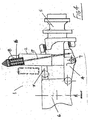
- Fig. 1 there is illustrated one side of an independent wheel suspension system according to the invention, indicated generally by the reference numeral 1, the other side of the system, which is located at an opposite side of the vehicle, being similar.
- the suspension system 1 incorporates a hydrostrut, hydraulic suspension actuator or hydro-pneumatic spring 2.
- the suspension system incorporates an upper control arm 3 and a lower control arm 4 to locate a wheel carrier 5 with respect to a vehicle body 6.
- the hydro-pneumatic spring 2 is connected at its upper end to the vehicle body 6 by an articulated joint 8 and at its lower end 7 to the lower control arm 4. It will be understood that this type of suspension system is shown for the purpose of illustration only and that the invention may be used in conjunction with many different types of suspension system.
- the hydro-pneumatic spring 2 is under compression and provides the suspension force tending to extend the suspended wheel downwardly away from the vehicle body.
- the hydro-pneumatic spring 2 comprises an inner cylinder 9, an inner end of which is slidable within an outer cylinder 10.
- the inner cylinder 9 has an upper chamber containing a variable volume of gas 11 above a separator piston 12.
- the remaining volume 13 of inner cylinder 9 below the separator piston 12 forms a lower chamber which is filled with oil and communicates with an oil-filled outer cylinder volume 14 through a damper orifice 15.
- a compensating spring 16 is located internally of the inner cylinder 9 within the lower chamber below the separator piston 12.
- the compensating spring 16 free length and stiffness may be chosen to give a hydro-pneumatic spring force which decreases gradually from a suitable load level such as the static load value to zero at full rebound, as shown in Fig. 9.
- the upper control arm 3 has an inner end connected by an articulating joint 40 with the vehicle body 6.
- An outer end of the upper control arm 3 is connected by an articulating joint 41 with the wheel carrier 5 which is a wheel hub on which a wheel (not shown) is mounted.
- An inner end of the lower control arm 4 is mounted by an articulating joint 42 on the vehicle body 6.
- An outer end of the lower control arm 4 is connected to the wheel carrier 5 by an articulating joint 43.
- a check strap 17 is provided which serves to limit the extension of the hydro-pneumatic spring 2.
- the check strap 17 is located between the vehicle body 6 and the lower control arm 4.
- the compensating spring 16 is in this case located externally of the hydro-pneumatic spring 2 and in series with the check strap 17.
- the force in the compensating spring 16 counteracts the residual force in the hydro-pneumatic spring 2.
- the compensating spring 16 free length and stiffness may be chosen to give a resultant spring force which decreases gradually from a suitable load level such as the static load value to zero at full rebound as shown in Fig. 9.
- a suspension actuator or strut 18 which is mounted between the body at 8 and the lower control arm 4 at 7, is separate from the hydro-pneumatic spring element 19.
- the strut 18 has a piston 20 slidable within an associated cylinder 22.
- An oil chamber filled with an oil volume 14 is formed between an inner bore of the cylinder 22 and the piston 20.
- the hydro-pneumatic spring 19 is separated into chamber with a gas volume 11 and an associated chamber with oil volume 13 by a separator membrane or piston 12.
- the oil volume 13 communicates with the oil volume 14 in the suspension actuator or strut 18 through damping orifice 15.
- the compensating spring 16 is internal to the hydro-pneumatic spring element 19 and acts to reduce the force exerted by the gas on the oil as the gas volume increases towards its maximum value in precisely the same manner as in the embodiment illustrated in Fig. 3.
- FIG. 7 there is shown schematically another embodiment 60 which is largely similar to that of Fig. 6 and like parts are assigned the same reference numerals.
- the compensating spring 16 is located in the suspension strut 18 within the cylinder 22 beneath the piston 20.
- the strut piston 20 comes into contact with the compensating spring 16 as the suspension moves into rebound and the force in the compensating spring 16 counteracts the residual force in the suspension strut 18.
- Fig. 8 there is shown schematically another suspension system 70 in which parts similar to those described previously are assigned the same reference numerals.
- the suspension strut 18 is a double acting hydraulic ram separate from the hydro-pneumatic spring element 19 and the compensating spring 16 is a second hydro-pneumatic spring element connected to a rod end volume 21 of the suspension strut 18 which forms a second oil chamber in the cylinder between the piston 20 and an outer end of the cylinder 22 and acts to reduce the force exerted by the suspension strut 18 as it approaches full extension.
- the compensating spring 16 has a gas volume 30 and an oil volume 31 separated by a separator membrane or piston 12, the oil volume 31 being connected to the rod end volume 21 of the suspension strut 18.
- hydro-pneumatic spring 2 or strut 18, when used in an independent suspension system of the type shown in Figs. 1 and 4, may be mounted between the vehicle body 6 and either the upper control arm 3 or lower control arm 4.
Landscapes
- Engineering & Computer Science (AREA)
- Mechanical Engineering (AREA)
- General Engineering & Computer Science (AREA)
- Vehicle Body Suspensions (AREA)
Claims (5)
- Système de suspension (1) pour un véhicule, comprenant des moyens (2, 3, 4, 5) servant à soutenir une roue sur une caisse de véhicule (6), lesdits moyens de support de roue (2, 3, 4, 5) incluant un ressort hydro-pneumatique (2), un moyen à ressort de compensation (16) étant prévu lequel est associé au ressort hydro-pneumatique (2), ledit moyen à ressort de compensation (16) pouvant être actionné pour agir en opposition à la force exercée par le ressort hydro-pneumatique (2) lorsque ledit ressort hydro-pneumatique (2) se rapproche de son extension totale, le ressort hydro-pneumatique (2) étant pourvu d'une chambre à huile (13) et d'une chambre à gaz associée (11) alors qu'un piston de séparation (12) ou une membrane est montée entre elles, caractérisé en ce que le moyen à ressort de compensation (16) est positionné dans la chambre à huile (13) de telle sorte qu'au fur et à mesure que le ressort hydro-pneumatique (2) s'étend jusqu'à la position de rebond, le piston de séparation (10) va comprimer le moyen à ressort de compensation (16), le moyen à ressort (16) agissant de façon à réduire la force exercée par le piston de séparation (12) ou la membrane sur l'huile présente dans la chambre à huile (13).
- Système de suspension (1), selon la revendication 1, comprenant :un bras de commande supérieur (3),un bras de commande inférieur (4),lesdits bras de commande (3, 4) servant à soutenir un ensemble roue sur une caisse (6) de véhicule,chaque bras de commande (3, 4) ayant une extrémité interne et une extrémité externe,l'extrémité interne étant raccordée à la caisse du véhicule (6) par l'intermédiaire d'un raccord articulé (40, 42),l'extrémité externe étant raccordée à l'ensemble roue (5) par l'intermédiaire d'un raccord articulé (41, 43),un ressort hydro-pneumatique (2) ayant une extrémité supérieure et une extrémité inférieure,l'extrémité supérieure étant attachée à la caisse du véhicule (6),l'extrémité inférieure étant attachée à l'un des desdits bras de commande supérieur et inférieur (3, 4),un moyen à ressort de compensation (16) qui peut être actionné au fur et à mesure que ledit ressort hydro-pneumatique (2) se rapproche de son extension totale afin d'agir en opposition à la force exercée par le ressort hydro-pneumatique (2).
- Système de suspension (1), selon la revendication 1 ou 2, dans lequel le ressort de compensation comprend un élément élastique réalisé en matériau plein.
- Système de suspension (1), selon l'une quelconque des revendications précédentes, dans lequel un ressort à boudin (16) assure la fonction de ressort de compensation.
- Système de suspension (50), selon l'une quelconque des revendications précédentes, dans lequel le ressort hydro-pneumatique (19) possède un actionneur de suspension (18) qui est séparé d'un élément hydro-pneumatique (19) mais qui est raccordé de façon opérationnelle à ce dernier, l'actionneur de suspension (18) étant composé de deux parties, notamment un piston (20) lequel est monté de façon coulissante à l'intérieur d'un cylindre associé (22), une partie (20, 22) étant destinée à être raccordée à la caisse du véhicule (6), l'autre partie (20, 22) étant destinée à être raccordée au support de roue (3, 4), alors que l'élément hydro-pneumatique (19) possède une chambre (11) contenant de l'huile ainsi qu'une chambre (13) contenant du gaz lesquelles sont séparées par une membrane de séparation (12) ou un piston, une chambre à huile (14) prévue à l'intérieur du cylindre (22) étant formée entre une extrémité interne d'un alésage du cylindre (22) et le piston (20), ladite chambre à huile (14) dans le cylindre (22) étant en communication avec la chambre à huile (13) de l'élément hydro-pneumatique (19) grâce à un orifice d'amortissement (15).
Applications Claiming Priority (2)
| Application Number | Priority Date | Filing Date | Title |
|---|---|---|---|
| IE20010125 | 2001-02-09 | ||
| IE20010125 | 2001-02-09 |
Publications (3)
| Publication Number | Publication Date |
|---|---|
| EP1231085A2 EP1231085A2 (fr) | 2002-08-14 |
| EP1231085A3 EP1231085A3 (fr) | 2004-01-07 |
| EP1231085B1 true EP1231085B1 (fr) | 2007-04-25 |
Family
ID=11042733
Family Applications (1)
| Application Number | Title | Priority Date | Filing Date |
|---|---|---|---|
| EP02394020A Expired - Lifetime EP1231085B1 (fr) | 2001-02-09 | 2002-02-11 | Système de suspension hydropneumatique |
Country Status (4)
| Country | Link |
|---|---|
| US (5) | US20020109327A1 (fr) |
| EP (1) | EP1231085B1 (fr) |
| AT (1) | ATE360543T1 (fr) |
| DE (1) | DE60219708T2 (fr) |
Families Citing this family (20)
| Publication number | Priority date | Publication date | Assignee | Title |
|---|---|---|---|---|
| DE10231376B3 (de) * | 2002-07-11 | 2004-01-15 | Daimlerchrysler Ag | Fahrzeugstarrachse mit integrierten Längslenkern und Anbaukonsolen |
| US7083163B2 (en) * | 2003-09-19 | 2006-08-01 | Tenneco Automotive Operating Company Inc. | Booster with spring to adapt air spring pressure for load dependent shock absorber |
| US20100116608A1 (en) * | 2004-04-08 | 2010-05-13 | Hemscheidt Fahrwerktechnik Gmbh & Co. Kg | Suspension and damping device for motor vehicles |
| US20060021833A1 (en) * | 2004-04-08 | 2006-02-02 | Hemscheidt Fahrwerktechnik Gmbh & Co. Kg | Suspension and damping device for motor vehicles |
| DE202004005623U1 (de) * | 2004-04-08 | 2005-08-11 | Hemscheidt Fahrwerktechnik Gmbh & Co. Kg | Federungs- und Dämpfungseinrichtung für Kraftfahrzeuge |
| US8151953B2 (en) | 2004-04-08 | 2012-04-10 | Samsung Electronics Co., Ltd. | Suspension and damping device for motor vehicles |
| US7383914B2 (en) * | 2004-12-23 | 2008-06-10 | Cnh America Llc | Apparatus and method for reducing shear loading on elements connecting an axle and a chassis of a vehicle |
| DE202005011439U1 (de) | 2005-07-18 | 2006-11-23 | Hemscheidt Fahrwerktechnik Gmbh & Co. Kg | Federungseinrichtung für Kraftfahrzeuge |
| FR2894184A1 (fr) * | 2005-12-05 | 2007-06-08 | Peugeot Citroen Automobiles Sa | Dispositif formant butee de detente d'une suspension d'un vehicule notamment automobile |
| US7954792B2 (en) * | 2008-02-22 | 2011-06-07 | Axletech International IP Holdings, LLC. | Strut assembly with air spring |
| SE532525C2 (sv) | 2008-06-13 | 2010-02-16 | Stroemsholmen Ab | Hydropneumatisk fjädringsenhet |
| SE533002C2 (sv) * | 2008-10-20 | 2010-06-08 | Bae Systems Haegglunds Ab | Hjulupphängning för hjulfordon |
| CN102287472B (zh) * | 2011-08-09 | 2012-10-03 | 中国汽车工程研究院股份有限公司 | 串联型单筒磁流变油气弹簧 |
| FR2988453A1 (fr) * | 2012-03-22 | 2013-09-27 | Peugeot Citroen Automobiles Sa | Amortisseur hydraulique comprenant une chambre de compensation et une butee deportee |
| US9193242B2 (en) * | 2013-09-01 | 2015-11-24 | Saber Sohrabi | Air shock absorber with smart suspension system with height adjustment without losing comfort and safety |
| US9507037B2 (en) * | 2013-09-20 | 2016-11-29 | Pgs Geophysical As | Air-spring compensation in a piston-type marine vibrator |
| CN105059074B (zh) * | 2015-09-08 | 2018-02-02 | 北京航天发射技术研究所 | 具有过载保护功能的悬架限位器、悬架系统和车辆 |
| KR101997114B1 (ko) * | 2017-11-17 | 2019-10-17 | 동원정밀 주식회사 | 실린더형 차량의 현가장치 |
| US10828955B1 (en) * | 2018-06-29 | 2020-11-10 | Zoox, Inc. | Vehicle suspension system with remote actuation |
| CN110356181A (zh) * | 2019-07-17 | 2019-10-22 | 北京航天发射技术研究所 | 一种超重载底盘的大行程独立悬架系统 |
Family Cites Families (33)
| Publication number | Priority date | Publication date | Assignee | Title |
|---|---|---|---|---|
| US2522323A (en) * | 1944-08-28 | 1950-09-12 | Monroe Auto Equipment Co | Shock absorber seal structure |
| FR1256427A (fr) * | 1959-05-13 | 1961-03-17 | Volvo Ab | Dispositif hydropneumatique de suspension et d'amortissement pour véhicules |
| GB883161A (en) * | 1959-05-13 | 1961-11-22 | Volvo Ab | Improvements in hydropneumatic suspension and damping devices for vehicles |
| FR1239452A (fr) * | 1959-07-17 | 1960-08-26 | Dispositif pour assurer la correction d'assiette d'une suspension oléopneumatique | |
| US3162432A (en) * | 1963-03-27 | 1964-12-22 | Hughes Tool Co | Oleo strut |
| US3743109A (en) * | 1972-02-03 | 1973-07-03 | Pullman Inc | Hydraulic cushion device for railway vehicles |
| JPS50125418A (fr) * | 1974-03-19 | 1975-10-02 | ||
| US3966223A (en) * | 1974-11-08 | 1976-06-29 | Carr James P | Vehicle suspension |
| US3972551A (en) * | 1975-06-04 | 1976-08-03 | General Motors Corporation | Telescoping energy absorber for vehicle bumpers and method of assembly |
| FR2473144A1 (fr) * | 1980-01-04 | 1981-07-10 | Fournales France Sarl | Dispositif combine amortisseur et suspension pour vehicule |
| DE3174727D1 (en) * | 1980-11-25 | 1986-07-03 | Bayerische Motoren Werke Ag | Suspension system for vehicles |
| AU553238B2 (en) * | 1983-09-26 | 1986-07-10 | Nhk Spring Co. Ltd. | Vehicle hydropneumatic suspension |
| FR2557515B1 (fr) * | 1983-12-28 | 1986-05-16 | Citroen Sa | Suspension a garde au sol variable et butees suiveuses |
| US4807860A (en) * | 1984-06-28 | 1989-02-28 | Simons Stephen W | Motorcycle front fork anti-cavity damping system |
| JPS6146702A (ja) * | 1984-08-10 | 1986-03-07 | Toyota Motor Corp | サスペンシヨンのストラツトバ−装置 |
| JPS62258207A (ja) * | 1986-04-30 | 1987-11-10 | Sumio Sugawara | 複合流体圧シリンダ装置 |
| DE3824611A1 (de) * | 1988-07-20 | 1990-01-25 | Bayerische Motoren Werke Ag | Feder-daempfer-system fuer fahrzeuge |
| JPH02299914A (ja) * | 1989-05-16 | 1990-12-12 | Shoichi Nomoto | 車輪の懸架装置 |
| DE4014466A1 (de) * | 1990-05-07 | 1991-11-14 | Bosch Gmbh Robert | Fahrzeugfederung |
| US5570286A (en) * | 1993-12-23 | 1996-10-29 | Lord Corporation | Regenerative system including an energy transformer which requires no external power source to drive same |
| JP3485276B2 (ja) * | 1994-03-28 | 2004-01-13 | 富士重工業株式会社 | 車両の懸架装置 |
| GB2300892A (en) * | 1995-05-16 | 1996-11-20 | Lotus Car | A damper for a vehicle suspension system |
| FI107963B (fi) * | 1995-06-20 | 2001-10-31 | Instrumentarium Oy | Infrapunasäteilijä |
| US5836541A (en) * | 1997-03-05 | 1998-11-17 | Pham; Roger N. C. | Easily-convertible fixed-wing roadable aircraft |
| US5810130A (en) * | 1997-03-14 | 1998-09-22 | General Motors Corporation | Suspension damper with rebound cut-off |
| US5984060A (en) * | 1997-08-25 | 1999-11-16 | General Motors Corporation | Monotube strut assembly |
| US6260832B1 (en) * | 1997-12-17 | 2001-07-17 | Marzocchi S.P.A. | Shock absorber with adjustable compression and rebound |
| DE19801055C1 (de) * | 1998-01-14 | 1999-04-08 | Mannesmann Sachs Ag | Hydropneumatische Feder |
| US6311962B1 (en) * | 1998-02-03 | 2001-11-06 | Fox Factory, Inc. | Shock absorber with external air cylinder spring |
| US6135434A (en) * | 1998-02-03 | 2000-10-24 | Fox Factory, Inc. | Shock absorber with positive and negative gas spring chambers |
| US6036201A (en) * | 1998-02-23 | 2000-03-14 | General Dynamics Land Systems | Adjustable vehicle suspension |
| GB2347395B (en) * | 1999-03-04 | 2002-07-31 | Rover Group | Vehicle suspension dampers |
| DE10016641C2 (de) * | 2000-04-04 | 2002-06-13 | Daimler Chrysler Ag | Schwingungsdämpfer mit Zuganschlag |
-
2002
- 2002-02-11 AT AT02394020T patent/ATE360543T1/de not_active IP Right Cessation
- 2002-02-11 DE DE60219708T patent/DE60219708T2/de not_active Expired - Lifetime
- 2002-02-11 EP EP02394020A patent/EP1231085B1/fr not_active Expired - Lifetime
- 2002-02-11 US US10/071,083 patent/US20020109327A1/en not_active Abandoned
-
2004
- 2004-07-06 US US10/883,774 patent/US20040232606A1/en not_active Abandoned
-
2007
- 2007-01-17 US US11/653,831 patent/US20070132163A1/en not_active Abandoned
-
2009
- 2009-07-24 US US12/509,058 patent/US20100156012A1/en not_active Abandoned
-
2013
- 2013-01-18 US US13/744,721 patent/US20130127132A1/en not_active Abandoned
Also Published As
| Publication number | Publication date |
|---|---|
| ATE360543T1 (de) | 2007-05-15 |
| DE60219708D1 (de) | 2007-06-06 |
| US20100156012A1 (en) | 2010-06-24 |
| EP1231085A2 (fr) | 2002-08-14 |
| DE60219708T2 (de) | 2007-12-27 |
| US20020109327A1 (en) | 2002-08-15 |
| EP1231085A3 (fr) | 2004-01-07 |
| US20070132163A1 (en) | 2007-06-14 |
| US20040232606A1 (en) | 2004-11-25 |
| US20130127132A1 (en) | 2013-05-23 |
Similar Documents
| Publication | Publication Date | Title |
|---|---|---|
| US20100156012A1 (en) | Hydro-pneumatic suspension system | |
| EP1664578B1 (fr) | Derivation dependant de la course | |
| US8256749B2 (en) | Strut assembly with air spring | |
| JP3538364B2 (ja) | ショックアブソーバ | |
| EP1259742B1 (fr) | Amortisseur a fluide compressible | |
| US4607861A (en) | Hydraulic stabilizing system for vehicle suspension | |
| EP2892740B1 (fr) | Ressort à air avec une constante de raideur linéarisé | |
| CA2398595A1 (fr) | Amortisseur reglable par voie pneumatique | |
| JPS63159119A (ja) | サスペンション装置および流体シリンダ装置 | |
| EP1663678A2 (fr) | Surpresseur a ressort pour l'adaptation de la pression de suspension pneumatique pour amortisseur a dependance de charge | |
| US4903984A (en) | Suspension device | |
| WO2005032861A2 (fr) | Amplificateur permettant d'adapter la pression du ressort pneumatique a l'amortisseur fdd | |
| US6988599B2 (en) | Compressible fluid strut | |
| US20040119250A1 (en) | Spring arrangement including a spring and shock absorber assembly | |
| IE20020093A1 (en) | Hydro-pneumatic suspension system | |
| US8087646B2 (en) | Hydropneumatic suspension with load-dependent damping control | |
| JPH02109713A (ja) | サスペンション装置 | |
| JPS5841398Y2 (ja) | カ−トリツジシヨツクアブソ−バ | |
| US10118456B2 (en) | Load leveling emulsion suspension system | |
| US20230067276A1 (en) | Shock absorber | |
| CA2267553C (fr) | Ressort pneumatique progressif | |
| AU3942000A (en) | Suspension apparatus |
Legal Events
| Date | Code | Title | Description |
|---|---|---|---|
| PUAI | Public reference made under article 153(3) epc to a published international application that has entered the european phase |
Free format text: ORIGINAL CODE: 0009012 |
|
| AK | Designated contracting states |
Kind code of ref document: A2 Designated state(s): AT BE CH CY DE DK ES FI FR GB GR IE IT LI LU MC NL PT SE TR |
|
| AX | Request for extension of the european patent |
Free format text: AL;LT;LV;MK;RO;SI |
|
| PUAL | Search report despatched |
Free format text: ORIGINAL CODE: 0009013 |
|
| AK | Designated contracting states |
Kind code of ref document: A3 Designated state(s): AT BE CH CY DE DK ES FI FR GB GR IE IT LI LU MC NL PT SE TR |
|
| AX | Request for extension of the european patent |
Extension state: AL LT LV MK RO SI |
|
| AKX | Designation fees paid | ||
| REG | Reference to a national code |
Ref country code: DE Ref legal event code: 8566 |
|
| 17P | Request for examination filed |
Effective date: 20040922 |
|
| RBV | Designated contracting states (corrected) |
Designated state(s): AT BE CH CY DE DK ES FI FR GB GR IE IT LI LU MC NL PT SE TR |
|
| 17Q | First examination report despatched |
Effective date: 20041229 |
|
| GRAP | Despatch of communication of intention to grant a patent |
Free format text: ORIGINAL CODE: EPIDOSNIGR1 |
|
| GRAS | Grant fee paid |
Free format text: ORIGINAL CODE: EPIDOSNIGR3 |
|
| GRAA | (expected) grant |
Free format text: ORIGINAL CODE: 0009210 |
|
| AK | Designated contracting states |
Kind code of ref document: B1 Designated state(s): AT BE CH CY DE DK ES FI FR GB GR IE IT LI LU MC NL PT SE TR |
|
| PG25 | Lapsed in a contracting state [announced via postgrant information from national office to epo] |
Ref country code: LI Free format text: LAPSE BECAUSE OF FAILURE TO SUBMIT A TRANSLATION OF THE DESCRIPTION OR TO PAY THE FEE WITHIN THE PRESCRIBED TIME-LIMIT Effective date: 20070425 Ref country code: FI Free format text: LAPSE BECAUSE OF FAILURE TO SUBMIT A TRANSLATION OF THE DESCRIPTION OR TO PAY THE FEE WITHIN THE PRESCRIBED TIME-LIMIT Effective date: 20070425 Ref country code: CH Free format text: LAPSE BECAUSE OF FAILURE TO SUBMIT A TRANSLATION OF THE DESCRIPTION OR TO PAY THE FEE WITHIN THE PRESCRIBED TIME-LIMIT Effective date: 20070425 |
|
| REG | Reference to a national code |
Ref country code: GB Ref legal event code: FG4D |
|
| REG | Reference to a national code |
Ref country code: IE Ref legal event code: FG4D |
|
| REG | Reference to a national code |
Ref country code: CH Ref legal event code: EP |
|
| REF | Corresponds to: |
Ref document number: 60219708 Country of ref document: DE Date of ref document: 20070606 Kind code of ref document: P |
|
| PG25 | Lapsed in a contracting state [announced via postgrant information from national office to epo] |
Ref country code: SE Free format text: LAPSE BECAUSE OF FAILURE TO SUBMIT A TRANSLATION OF THE DESCRIPTION OR TO PAY THE FEE WITHIN THE PRESCRIBED TIME-LIMIT Effective date: 20070725 |
|
| PG25 | Lapsed in a contracting state [announced via postgrant information from national office to epo] |
Ref country code: ES Free format text: LAPSE BECAUSE OF FAILURE TO SUBMIT A TRANSLATION OF THE DESCRIPTION OR TO PAY THE FEE WITHIN THE PRESCRIBED TIME-LIMIT Effective date: 20070805 |
|
| PG25 | Lapsed in a contracting state [announced via postgrant information from national office to epo] |
Ref country code: PT Free format text: LAPSE BECAUSE OF FAILURE TO SUBMIT A TRANSLATION OF THE DESCRIPTION OR TO PAY THE FEE WITHIN THE PRESCRIBED TIME-LIMIT Effective date: 20070925 |
|
| REG | Reference to a national code |
Ref country code: CH Ref legal event code: PL |
|
| NLV1 | Nl: lapsed or annulled due to failure to fulfill the requirements of art. 29p and 29m of the patents act | ||
| ET | Fr: translation filed | ||
| PG25 | Lapsed in a contracting state [announced via postgrant information from national office to epo] |
Ref country code: AT Free format text: LAPSE BECAUSE OF FAILURE TO SUBMIT A TRANSLATION OF THE DESCRIPTION OR TO PAY THE FEE WITHIN THE PRESCRIBED TIME-LIMIT Effective date: 20070425 |
|
| PG25 | Lapsed in a contracting state [announced via postgrant information from national office to epo] |
Ref country code: BE Free format text: LAPSE BECAUSE OF FAILURE TO SUBMIT A TRANSLATION OF THE DESCRIPTION OR TO PAY THE FEE WITHIN THE PRESCRIBED TIME-LIMIT Effective date: 20070425 |
|
| PG25 | Lapsed in a contracting state [announced via postgrant information from national office to epo] |
Ref country code: NL Free format text: LAPSE BECAUSE OF FAILURE TO SUBMIT A TRANSLATION OF THE DESCRIPTION OR TO PAY THE FEE WITHIN THE PRESCRIBED TIME-LIMIT Effective date: 20070425 |
|
| PLBE | No opposition filed within time limit |
Free format text: ORIGINAL CODE: 0009261 |
|
| STAA | Information on the status of an ep patent application or granted ep patent |
Free format text: STATUS: NO OPPOSITION FILED WITHIN TIME LIMIT |
|
| 26N | No opposition filed |
Effective date: 20080128 |
|
| PG25 | Lapsed in a contracting state [announced via postgrant information from national office to epo] |
Ref country code: IT Free format text: LAPSE BECAUSE OF FAILURE TO SUBMIT A TRANSLATION OF THE DESCRIPTION OR TO PAY THE FEE WITHIN THE PRESCRIBED TIME-LIMIT Effective date: 20070425 Ref country code: GR Free format text: LAPSE BECAUSE OF FAILURE TO SUBMIT A TRANSLATION OF THE DESCRIPTION OR TO PAY THE FEE WITHIN THE PRESCRIBED TIME-LIMIT Effective date: 20070726 |
|
| PG25 | Lapsed in a contracting state [announced via postgrant information from national office to epo] |
Ref country code: MC Free format text: LAPSE BECAUSE OF NON-PAYMENT OF DUE FEES Effective date: 20080228 |
|
| PG25 | Lapsed in a contracting state [announced via postgrant information from national office to epo] |
Ref country code: CY Free format text: LAPSE BECAUSE OF FAILURE TO SUBMIT A TRANSLATION OF THE DESCRIPTION OR TO PAY THE FEE WITHIN THE PRESCRIBED TIME-LIMIT Effective date: 20070425 |
|
| PG25 | Lapsed in a contracting state [announced via postgrant information from national office to epo] |
Ref country code: DK Free format text: LAPSE BECAUSE OF FAILURE TO SUBMIT A TRANSLATION OF THE DESCRIPTION OR TO PAY THE FEE WITHIN THE PRESCRIBED TIME-LIMIT Effective date: 20070425 |
|
| PG25 | Lapsed in a contracting state [announced via postgrant information from national office to epo] |
Ref country code: LU Free format text: LAPSE BECAUSE OF NON-PAYMENT OF DUE FEES Effective date: 20080211 |
|
| PG25 | Lapsed in a contracting state [announced via postgrant information from national office to epo] |
Ref country code: TR Free format text: LAPSE BECAUSE OF FAILURE TO SUBMIT A TRANSLATION OF THE DESCRIPTION OR TO PAY THE FEE WITHIN THE PRESCRIBED TIME-LIMIT Effective date: 20070425 |
|
| REG | Reference to a national code |
Ref country code: FR Ref legal event code: PLFP Year of fee payment: 14 |
|
| PGFP | Annual fee paid to national office [announced via postgrant information from national office to epo] |
Ref country code: IE Payment date: 20150213 Year of fee payment: 14 Ref country code: DE Payment date: 20150226 Year of fee payment: 14 |
|
| PGFP | Annual fee paid to national office [announced via postgrant information from national office to epo] |
Ref country code: FR Payment date: 20150225 Year of fee payment: 14 |
|
| REG | Reference to a national code |
Ref country code: DE Ref legal event code: R119 Ref document number: 60219708 Country of ref document: DE |
|
| REG | Reference to a national code |
Ref country code: FR Ref legal event code: ST Effective date: 20161028 |
|
| REG | Reference to a national code |
Ref country code: IE Ref legal event code: MM4A |
|
| PG25 | Lapsed in a contracting state [announced via postgrant information from national office to epo] |
Ref country code: DE Free format text: LAPSE BECAUSE OF NON-PAYMENT OF DUE FEES Effective date: 20160901 Ref country code: IE Free format text: LAPSE BECAUSE OF NON-PAYMENT OF DUE FEES Effective date: 20160211 Ref country code: FR Free format text: LAPSE BECAUSE OF NON-PAYMENT OF DUE FEES Effective date: 20160229 |
|
| PGFP | Annual fee paid to national office [announced via postgrant information from national office to epo] |
Ref country code: GB Payment date: 20170228 Year of fee payment: 16 |
|
| GBPC | Gb: european patent ceased through non-payment of renewal fee |
Effective date: 20180211 |
|
| PG25 | Lapsed in a contracting state [announced via postgrant information from national office to epo] |
Ref country code: GB Free format text: LAPSE BECAUSE OF NON-PAYMENT OF DUE FEES Effective date: 20180211 |