EP1231092B1 - Réduction du nombre des cycles de démarrage et arrêt d'un moteur à combustion dans un véhicule hybride - Google Patents
Réduction du nombre des cycles de démarrage et arrêt d'un moteur à combustion dans un véhicule hybride Download PDFInfo
- Publication number
- EP1231092B1 EP1231092B1 EP01000452A EP01000452A EP1231092B1 EP 1231092 B1 EP1231092 B1 EP 1231092B1 EP 01000452 A EP01000452 A EP 01000452A EP 01000452 A EP01000452 A EP 01000452A EP 1231092 B1 EP1231092 B1 EP 1231092B1
- Authority
- EP
- European Patent Office
- Prior art keywords
- unit
- threshold value
- status
- value
- parameter
- Prior art date
- Legal status (The legal status is an assumption and is not a legal conclusion. Google has not performed a legal analysis and makes no representation as to the accuracy of the status listed.)
- Expired - Lifetime
Links
Images

Classifications
-
- B—PERFORMING OPERATIONS; TRANSPORTING
- B60—VEHICLES IN GENERAL
- B60W—CONJOINT CONTROL OF VEHICLE SUB-UNITS OF DIFFERENT TYPE OR DIFFERENT FUNCTION; CONTROL SYSTEMS SPECIALLY ADAPTED FOR HYBRID VEHICLES; ROAD VEHICLE DRIVE CONTROL SYSTEMS FOR PURPOSES NOT RELATED TO THE CONTROL OF A PARTICULAR SUB-UNIT
- B60W20/00—Control systems specially adapted for hybrid vehicles
-
- B—PERFORMING OPERATIONS; TRANSPORTING
- B60—VEHICLES IN GENERAL
- B60K—ARRANGEMENT OR MOUNTING OF PROPULSION UNITS OR OF TRANSMISSIONS IN VEHICLES; ARRANGEMENT OR MOUNTING OF PLURAL DIVERSE PRIME-MOVERS IN VEHICLES; AUXILIARY DRIVES FOR VEHICLES; INSTRUMENTATION OR DASHBOARDS FOR VEHICLES; ARRANGEMENTS IN CONNECTION WITH COOLING, AIR INTAKE, GAS EXHAUST OR FUEL SUPPLY OF PROPULSION UNITS IN VEHICLES
- B60K6/00—Arrangement or mounting of plural diverse prime-movers for mutual or common propulsion, e.g. hybrid propulsion systems comprising electric motors and internal combustion engines
- B60K6/20—Arrangement or mounting of plural diverse prime-movers for mutual or common propulsion, e.g. hybrid propulsion systems comprising electric motors and internal combustion engines the prime-movers consisting of electric motors and internal combustion engines, e.g. HEVs
- B60K6/42—Arrangement or mounting of plural diverse prime-movers for mutual or common propulsion, e.g. hybrid propulsion systems comprising electric motors and internal combustion engines the prime-movers consisting of electric motors and internal combustion engines, e.g. HEVs characterised by the architecture of the hybrid electric vehicle
- B60K6/48—Parallel type
-
- B—PERFORMING OPERATIONS; TRANSPORTING
- B60—VEHICLES IN GENERAL
- B60K—ARRANGEMENT OR MOUNTING OF PROPULSION UNITS OR OF TRANSMISSIONS IN VEHICLES; ARRANGEMENT OR MOUNTING OF PLURAL DIVERSE PRIME-MOVERS IN VEHICLES; AUXILIARY DRIVES FOR VEHICLES; INSTRUMENTATION OR DASHBOARDS FOR VEHICLES; ARRANGEMENTS IN CONNECTION WITH COOLING, AIR INTAKE, GAS EXHAUST OR FUEL SUPPLY OF PROPULSION UNITS IN VEHICLES
- B60K6/00—Arrangement or mounting of plural diverse prime-movers for mutual or common propulsion, e.g. hybrid propulsion systems comprising electric motors and internal combustion engines
- B60K6/20—Arrangement or mounting of plural diverse prime-movers for mutual or common propulsion, e.g. hybrid propulsion systems comprising electric motors and internal combustion engines the prime-movers consisting of electric motors and internal combustion engines, e.g. HEVs
- B60K6/50—Architecture of the driveline characterised by arrangement or kind of transmission units
- B60K6/54—Transmission for changing ratio
- B60K6/543—Transmission for changing ratio the transmission being a continuously variable transmission
-
- B—PERFORMING OPERATIONS; TRANSPORTING
- B60—VEHICLES IN GENERAL
- B60T—VEHICLE BRAKE CONTROL SYSTEMS OR PARTS THEREOF; BRAKE CONTROL SYSTEMS OR PARTS THEREOF, IN GENERAL; ARRANGEMENT OF BRAKING ELEMENTS ON VEHICLES IN GENERAL; PORTABLE DEVICES FOR PREVENTING UNWANTED MOVEMENT OF VEHICLES; VEHICLE MODIFICATIONS TO FACILITATE COOLING OF BRAKES
- B60T13/00—Transmitting braking action from initiating means to ultimate brake actuator with power assistance or drive; Brake systems incorporating such transmitting means, e.g. air-pressure brake systems
- B60T13/10—Transmitting braking action from initiating means to ultimate brake actuator with power assistance or drive; Brake systems incorporating such transmitting means, e.g. air-pressure brake systems with fluid assistance, drive, or release
- B60T13/24—Transmitting braking action from initiating means to ultimate brake actuator with power assistance or drive; Brake systems incorporating such transmitting means, e.g. air-pressure brake systems with fluid assistance, drive, or release the fluid being gaseous
- B60T13/46—Vacuum systems
-
- B—PERFORMING OPERATIONS; TRANSPORTING
- B60—VEHICLES IN GENERAL
- B60T—VEHICLE BRAKE CONTROL SYSTEMS OR PARTS THEREOF; BRAKE CONTROL SYSTEMS OR PARTS THEREOF, IN GENERAL; ARRANGEMENT OF BRAKING ELEMENTS ON VEHICLES IN GENERAL; PORTABLE DEVICES FOR PREVENTING UNWANTED MOVEMENT OF VEHICLES; VEHICLE MODIFICATIONS TO FACILITATE COOLING OF BRAKES
- B60T17/00—Component parts, details, or accessories of power brake systems not covered by groups B60T8/00, B60T13/00 or B60T15/00, or presenting other characteristic features
- B60T17/02—Arrangements of pumps or compressors, or control devices therefor
-
- B—PERFORMING OPERATIONS; TRANSPORTING
- B60—VEHICLES IN GENERAL
- B60W—CONJOINT CONTROL OF VEHICLE SUB-UNITS OF DIFFERENT TYPE OR DIFFERENT FUNCTION; CONTROL SYSTEMS SPECIALLY ADAPTED FOR HYBRID VEHICLES; ROAD VEHICLE DRIVE CONTROL SYSTEMS FOR PURPOSES NOT RELATED TO THE CONTROL OF A PARTICULAR SUB-UNIT
- B60W10/00—Conjoint control of vehicle sub-units of different type or different function
- B60W10/04—Conjoint control of vehicle sub-units of different type or different function including control of propulsion units
- B60W10/06—Conjoint control of vehicle sub-units of different type or different function including control of propulsion units including control of combustion engines
-
- B—PERFORMING OPERATIONS; TRANSPORTING
- B60—VEHICLES IN GENERAL
- B60W—CONJOINT CONTROL OF VEHICLE SUB-UNITS OF DIFFERENT TYPE OR DIFFERENT FUNCTION; CONTROL SYSTEMS SPECIALLY ADAPTED FOR HYBRID VEHICLES; ROAD VEHICLE DRIVE CONTROL SYSTEMS FOR PURPOSES NOT RELATED TO THE CONTROL OF A PARTICULAR SUB-UNIT
- B60W10/00—Conjoint control of vehicle sub-units of different type or different function
- B60W10/04—Conjoint control of vehicle sub-units of different type or different function including control of propulsion units
- B60W10/08—Conjoint control of vehicle sub-units of different type or different function including control of propulsion units including control of electric propulsion units, e.g. motors or generators
-
- B—PERFORMING OPERATIONS; TRANSPORTING
- B60—VEHICLES IN GENERAL
- B60W—CONJOINT CONTROL OF VEHICLE SUB-UNITS OF DIFFERENT TYPE OR DIFFERENT FUNCTION; CONTROL SYSTEMS SPECIALLY ADAPTED FOR HYBRID VEHICLES; ROAD VEHICLE DRIVE CONTROL SYSTEMS FOR PURPOSES NOT RELATED TO THE CONTROL OF A PARTICULAR SUB-UNIT
- B60W10/00—Conjoint control of vehicle sub-units of different type or different function
- B60W10/30—Conjoint control of vehicle sub-units of different type or different function including control of auxiliary equipment, e.g. air-conditioning compressors or oil pumps
-
- F—MECHANICAL ENGINEERING; LIGHTING; HEATING; WEAPONS; BLASTING
- F01—MACHINES OR ENGINES IN GENERAL; ENGINE PLANTS IN GENERAL; STEAM ENGINES
- F01N—GAS-FLOW SILENCERS OR EXHAUST APPARATUS FOR MACHINES OR ENGINES IN GENERAL; GAS-FLOW SILENCERS OR EXHAUST APPARATUS FOR INTERNAL-COMBUSTION ENGINES
- F01N3/00—Exhaust or silencing apparatus having means for purifying, rendering innocuous, or otherwise treating exhaust
- F01N3/08—Exhaust or silencing apparatus having means for purifying, rendering innocuous, or otherwise treating exhaust for rendering innocuous
- F01N3/10—Exhaust or silencing apparatus having means for purifying, rendering innocuous, or otherwise treating exhaust for rendering innocuous by thermal or catalytic conversion of noxious components of exhaust
- F01N3/18—Exhaust or silencing apparatus having means for purifying, rendering innocuous, or otherwise treating exhaust for rendering innocuous by thermal or catalytic conversion of noxious components of exhaust characterised by methods of operation; Control
- F01N3/20—Exhaust or silencing apparatus having means for purifying, rendering innocuous, or otherwise treating exhaust for rendering innocuous by thermal or catalytic conversion of noxious components of exhaust characterised by methods of operation; Control specially adapted for catalytic conversion
- F01N3/2006—Periodically heating or cooling catalytic reactors, e.g. at cold starting or overheating
- F01N3/2013—Periodically heating or cooling catalytic reactors, e.g. at cold starting or overheating using electric or magnetic heating means
-
- F—MECHANICAL ENGINEERING; LIGHTING; HEATING; WEAPONS; BLASTING
- F02—COMBUSTION ENGINES; HOT-GAS OR COMBUSTION-PRODUCT ENGINE PLANTS
- F02D—CONTROLLING COMBUSTION ENGINES
- F02D41/00—Electrical control of supply of combustible mixture or its constituents
- F02D41/02—Circuit arrangements for generating control signals
- F02D41/021—Introducing corrections for particular conditions exterior to the engine
- F02D41/0235—Introducing corrections for particular conditions exterior to the engine in relation with the state of the exhaust gas treating apparatus
- F02D41/024—Introducing corrections for particular conditions exterior to the engine in relation with the state of the exhaust gas treating apparatus to increase temperature of the exhaust gas treating apparatus
-
- F—MECHANICAL ENGINEERING; LIGHTING; HEATING; WEAPONS; BLASTING
- F02—COMBUSTION ENGINES; HOT-GAS OR COMBUSTION-PRODUCT ENGINE PLANTS
- F02D—CONTROLLING COMBUSTION ENGINES
- F02D41/00—Electrical control of supply of combustible mixture or its constituents
- F02D41/02—Circuit arrangements for generating control signals
- F02D41/04—Introducing corrections for particular operating conditions
- F02D41/06—Introducing corrections for particular operating conditions for engine starting or warming up
- F02D41/062—Introducing corrections for particular operating conditions for engine starting or warming up for starting
-
- F—MECHANICAL ENGINEERING; LIGHTING; HEATING; WEAPONS; BLASTING
- F02—COMBUSTION ENGINES; HOT-GAS OR COMBUSTION-PRODUCT ENGINE PLANTS
- F02D—CONTROLLING COMBUSTION ENGINES
- F02D41/00—Electrical control of supply of combustible mixture or its constituents
- F02D41/02—Circuit arrangements for generating control signals
- F02D41/04—Introducing corrections for particular operating conditions
- F02D41/08—Introducing corrections for particular operating conditions for idling
- F02D41/083—Introducing corrections for particular operating conditions for idling taking into account engine load variation, e.g. air-conditionning
-
- F—MECHANICAL ENGINEERING; LIGHTING; HEATING; WEAPONS; BLASTING
- F02—COMBUSTION ENGINES; HOT-GAS OR COMBUSTION-PRODUCT ENGINE PLANTS
- F02N—STARTING OF COMBUSTION ENGINES; STARTING AIDS FOR SUCH ENGINES, NOT OTHERWISE PROVIDED FOR
- F02N11/00—Starting of engines by means of electric motors
- F02N11/08—Circuits specially adapted for starting of engines
- F02N11/0814—Circuits specially adapted for starting of engines comprising means for controlling automatic idle-start-stop
- F02N11/0818—Conditions for starting or stopping the engine or for deactivating the idle-start-stop mode
- F02N11/0829—Conditions for starting or stopping the engine or for deactivating the idle-start-stop mode related to special engine control, e.g. giving priority to engine warming-up or learning
-
- F—MECHANICAL ENGINEERING; LIGHTING; HEATING; WEAPONS; BLASTING
- F02—COMBUSTION ENGINES; HOT-GAS OR COMBUSTION-PRODUCT ENGINE PLANTS
- F02N—STARTING OF COMBUSTION ENGINES; STARTING AIDS FOR SUCH ENGINES, NOT OTHERWISE PROVIDED FOR
- F02N11/00—Starting of engines by means of electric motors
- F02N11/08—Circuits specially adapted for starting of engines
- F02N11/0814—Circuits specially adapted for starting of engines comprising means for controlling automatic idle-start-stop
- F02N11/0818—Conditions for starting or stopping the engine or for deactivating the idle-start-stop mode
- F02N11/0833—Vehicle conditions
- F02N11/084—State of vehicle accessories, e.g. air condition or power steering
-
- B—PERFORMING OPERATIONS; TRANSPORTING
- B60—VEHICLES IN GENERAL
- B60L—PROPULSION OF ELECTRICALLY-PROPELLED VEHICLES; SUPPLYING ELECTRIC POWER FOR AUXILIARY EQUIPMENT OF ELECTRICALLY-PROPELLED VEHICLES; ELECTRODYNAMIC BRAKE SYSTEMS FOR VEHICLES IN GENERAL; MAGNETIC SUSPENSION OR LEVITATION FOR VEHICLES; MONITORING OPERATING VARIABLES OF ELECTRICALLY-PROPELLED VEHICLES; ELECTRIC SAFETY DEVICES FOR ELECTRICALLY-PROPELLED VEHICLES
- B60L2240/00—Control parameters of input or output; Target parameters
- B60L2240/40—Drive Train control parameters
- B60L2240/44—Drive Train control parameters related to combustion engines
- B60L2240/445—Temperature
-
- B—PERFORMING OPERATIONS; TRANSPORTING
- B60—VEHICLES IN GENERAL
- B60W—CONJOINT CONTROL OF VEHICLE SUB-UNITS OF DIFFERENT TYPE OR DIFFERENT FUNCTION; CONTROL SYSTEMS SPECIALLY ADAPTED FOR HYBRID VEHICLES; ROAD VEHICLE DRIVE CONTROL SYSTEMS FOR PURPOSES NOT RELATED TO THE CONTROL OF A PARTICULAR SUB-UNIT
- B60W2510/00—Input parameters relating to a particular sub-units
- B60W2510/06—Combustion engines, Gas turbines
- B60W2510/068—Engine exhaust temperature
-
- B—PERFORMING OPERATIONS; TRANSPORTING
- B60—VEHICLES IN GENERAL
- B60W—CONJOINT CONTROL OF VEHICLE SUB-UNITS OF DIFFERENT TYPE OR DIFFERENT FUNCTION; CONTROL SYSTEMS SPECIALLY ADAPTED FOR HYBRID VEHICLES; ROAD VEHICLE DRIVE CONTROL SYSTEMS FOR PURPOSES NOT RELATED TO THE CONTROL OF A PARTICULAR SUB-UNIT
- B60W2540/00—Input parameters relating to occupants
- B60W2540/12—Brake pedal position
-
- F—MECHANICAL ENGINEERING; LIGHTING; HEATING; WEAPONS; BLASTING
- F01—MACHINES OR ENGINES IN GENERAL; ENGINE PLANTS IN GENERAL; STEAM ENGINES
- F01N—GAS-FLOW SILENCERS OR EXHAUST APPARATUS FOR MACHINES OR ENGINES IN GENERAL; GAS-FLOW SILENCERS OR EXHAUST APPARATUS FOR INTERNAL-COMBUSTION ENGINES
- F01N2550/00—Monitoring or diagnosing the deterioration of exhaust systems
- F01N2550/02—Catalytic activity of catalytic converters
-
- F—MECHANICAL ENGINEERING; LIGHTING; HEATING; WEAPONS; BLASTING
- F02—COMBUSTION ENGINES; HOT-GAS OR COMBUSTION-PRODUCT ENGINE PLANTS
- F02D—CONTROLLING COMBUSTION ENGINES
- F02D2250/00—Engine control related to specific problems or objectives
- F02D2250/41—Control to generate negative pressure in the intake manifold, e.g. for fuel vapor purging or brake booster
-
- F—MECHANICAL ENGINEERING; LIGHTING; HEATING; WEAPONS; BLASTING
- F02—COMBUSTION ENGINES; HOT-GAS OR COMBUSTION-PRODUCT ENGINE PLANTS
- F02D—CONTROLLING COMBUSTION ENGINES
- F02D41/00—Electrical control of supply of combustible mixture or its constituents
- F02D41/0025—Controlling engines characterised by use of non-liquid fuels, pluralities of fuels, or non-fuel substances added to the combustible mixtures
- F02D41/003—Adding fuel vapours, e.g. drawn from engine fuel reservoir
- F02D41/0045—Estimating, calculating or determining the purging rate, amount, flow or concentration
-
- F—MECHANICAL ENGINEERING; LIGHTING; HEATING; WEAPONS; BLASTING
- F02—COMBUSTION ENGINES; HOT-GAS OR COMBUSTION-PRODUCT ENGINE PLANTS
- F02D—CONTROLLING COMBUSTION ENGINES
- F02D41/00—Electrical control of supply of combustible mixture or its constituents
- F02D41/02—Circuit arrangements for generating control signals
- F02D41/04—Introducing corrections for particular operating conditions
- F02D41/042—Introducing corrections for particular operating conditions for stopping the engine
-
- F—MECHANICAL ENGINEERING; LIGHTING; HEATING; WEAPONS; BLASTING
- F02—COMBUSTION ENGINES; HOT-GAS OR COMBUSTION-PRODUCT ENGINE PLANTS
- F02N—STARTING OF COMBUSTION ENGINES; STARTING AIDS FOR SUCH ENGINES, NOT OTHERWISE PROVIDED FOR
- F02N2200/00—Parameters used for control of starting apparatus
- F02N2200/02—Parameters used for control of starting apparatus said parameters being related to the engine
- F02N2200/026—Catalyst temperature
-
- F—MECHANICAL ENGINEERING; LIGHTING; HEATING; WEAPONS; BLASTING
- F02—COMBUSTION ENGINES; HOT-GAS OR COMBUSTION-PRODUCT ENGINE PLANTS
- F02N—STARTING OF COMBUSTION ENGINES; STARTING AIDS FOR SUCH ENGINES, NOT OTHERWISE PROVIDED FOR
- F02N2200/00—Parameters used for control of starting apparatus
- F02N2200/08—Parameters used for control of starting apparatus said parameters being related to the vehicle or its components
- F02N2200/0806—Air condition state
-
- F—MECHANICAL ENGINEERING; LIGHTING; HEATING; WEAPONS; BLASTING
- F02—COMBUSTION ENGINES; HOT-GAS OR COMBUSTION-PRODUCT ENGINE PLANTS
- F02N—STARTING OF COMBUSTION ENGINES; STARTING AIDS FOR SUCH ENGINES, NOT OTHERWISE PROVIDED FOR
- F02N2200/00—Parameters used for control of starting apparatus
- F02N2200/08—Parameters used for control of starting apparatus said parameters being related to the vehicle or its components
- F02N2200/0807—Brake booster state
-
- Y—GENERAL TAGGING OF NEW TECHNOLOGICAL DEVELOPMENTS; GENERAL TAGGING OF CROSS-SECTIONAL TECHNOLOGIES SPANNING OVER SEVERAL SECTIONS OF THE IPC; TECHNICAL SUBJECTS COVERED BY FORMER USPC CROSS-REFERENCE ART COLLECTIONS [XRACs] AND DIGESTS
- Y02—TECHNOLOGIES OR APPLICATIONS FOR MITIGATION OR ADAPTATION AGAINST CLIMATE CHANGE
- Y02A—TECHNOLOGIES FOR ADAPTATION TO CLIMATE CHANGE
- Y02A50/00—TECHNOLOGIES FOR ADAPTATION TO CLIMATE CHANGE in human health protection, e.g. against extreme weather
- Y02A50/20—Air quality improvement or preservation, e.g. vehicle emission control or emission reduction by using catalytic converters
-
- Y—GENERAL TAGGING OF NEW TECHNOLOGICAL DEVELOPMENTS; GENERAL TAGGING OF CROSS-SECTIONAL TECHNOLOGIES SPANNING OVER SEVERAL SECTIONS OF THE IPC; TECHNICAL SUBJECTS COVERED BY FORMER USPC CROSS-REFERENCE ART COLLECTIONS [XRACs] AND DIGESTS
- Y02—TECHNOLOGIES OR APPLICATIONS FOR MITIGATION OR ADAPTATION AGAINST CLIMATE CHANGE
- Y02T—CLIMATE CHANGE MITIGATION TECHNOLOGIES RELATED TO TRANSPORTATION
- Y02T10/00—Road transport of goods or passengers
- Y02T10/10—Internal combustion engine [ICE] based vehicles
- Y02T10/12—Improving ICE efficiencies
-
- Y—GENERAL TAGGING OF NEW TECHNOLOGICAL DEVELOPMENTS; GENERAL TAGGING OF CROSS-SECTIONAL TECHNOLOGIES SPANNING OVER SEVERAL SECTIONS OF THE IPC; TECHNICAL SUBJECTS COVERED BY FORMER USPC CROSS-REFERENCE ART COLLECTIONS [XRACs] AND DIGESTS
- Y02—TECHNOLOGIES OR APPLICATIONS FOR MITIGATION OR ADAPTATION AGAINST CLIMATE CHANGE
- Y02T—CLIMATE CHANGE MITIGATION TECHNOLOGIES RELATED TO TRANSPORTATION
- Y02T10/00—Road transport of goods or passengers
- Y02T10/10—Internal combustion engine [ICE] based vehicles
- Y02T10/40—Engine management systems
-
- Y—GENERAL TAGGING OF NEW TECHNOLOGICAL DEVELOPMENTS; GENERAL TAGGING OF CROSS-SECTIONAL TECHNOLOGIES SPANNING OVER SEVERAL SECTIONS OF THE IPC; TECHNICAL SUBJECTS COVERED BY FORMER USPC CROSS-REFERENCE ART COLLECTIONS [XRACs] AND DIGESTS
- Y02—TECHNOLOGIES OR APPLICATIONS FOR MITIGATION OR ADAPTATION AGAINST CLIMATE CHANGE
- Y02T—CLIMATE CHANGE MITIGATION TECHNOLOGIES RELATED TO TRANSPORTATION
- Y02T10/00—Road transport of goods or passengers
- Y02T10/60—Other road transportation technologies with climate change mitigation effect
- Y02T10/62—Hybrid vehicles
Definitions
- This invention relates in general to hybrid motor vehicles operable by either an electric motor or a liquid fuel powered internal combustion engine and, in particular, to a method and system for reducing the cycling of the engine during non-propulsive operations.
- a vehicle with such an alternative propulsion system is generally referred to as a hybrid motor vehicle.
- a hybrid electric vehicle is generally described as a motor vehicle with a main power unit (HPU) which converts fuel energy to electric and/or mechanical energy, and a bidirectional energy storage system (ESS), usually electrical.
- the main power unit may be a piston engine, gas turbine, fuel cell or the like, while the energy storage system may be a battery, flywheel, capacitor or the like.
- HPU High-power drive the vehicle
- ESS ESS
- HPU electric traction motor-generator
- ESS ESS
- Various hybrid configurations add HPU and ESS power in different places in the system.
- the emissions that occur at engine startup are at a high level due to the fact that the air/fuel ratio is not accurately determined on startup and the catalytic converter is usually cold (unless it is electrically heated).
- initial emissions are high due to low catalyst efficiency until the catalyst temperature is stabilized. It is, therefore, desirable to limit the frequency of engine starts in a given drive cycle. Emissions are much lower if the engine is requested to remain on for a short extended period beyond driver demand (accelerator) to satisfy ancillary requirements.
- the catalyst is sufficiently hot from the ongoing combustion process to perform the catalytic action required to maintain low emissions.
- Ancillary functions that require engine operation include, but are not limited to: brake booster vacuum, fuel vapor purge, and passenger compartment heating or air conditioning. It is an object of the present invention to reduce the number of times that the engine or other main power unit is turned on solely for supporting non-propulsive or ancillary functions to thereby enhance both fuel economy and reduce engine emissions.
- An engine stop and restart device has been proposed in EP 0990 793 for a vehicle provided with a brake booster using an intake negative pressure generated by the engine rotation as the boost source.
- the engine is stopped under certain conditions and restarted when the negative pressure decreases to a predetermined value or less during engine stop.
- Sufficient surge tank negative pressure that is, the brake booster negative pressure, is secured by restarting of the engine. This prevents the deterioration of the brake booster function resulting from increased engine stop frequency.
- US 4,416,230 discloses another engine control apparatus which interrupts the fuel supply to an engine under certain conditions but prevents the engine from being switched on when there is insufficient vacuum to operate a brake booster.
- a method of reducing the number of times a main power unit of a hybrid electric vehicle is activated to support an auxiliary system of the vehicle during a given drive cycle comprising a sequence of the following steps:
- the invention also provides a system implementing the above method as set forth in Claim 7 of the appended claims.
- the brake booster may be regarded as an auxiliary system of which a parameter, namely the boost pressure, is taken into consideration when switching the engine on and off.
- a parameter namely the boost pressure
- the present invention also sets a second threhold value and requires the parameter of the auxilary system to cross this second threshold before the engine is allowed to be switched off. In this way, the invention reduces the frequency with which the engine is switched on and off.
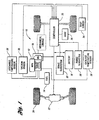
- the HEV 10 contains a main power unit (HPU) 12, for example an internal combustion engine, which uses fuel from an onboard fuel tank 14 to generate electricity in a motor-generator (MG) 16 to power the vehicle 10.
- HPU main power unit
- MG motor-generator
- ESS energy storage system
- a direct mechanical linkage shown in dashed lines, may be included to provide a parallel configuration.
- Both the HPU 12 and ESS 18 are under the control of a controller 20.
- the controller hardware is conventional and includes the usual components, such as a processor (“CPU”); input/ output ports; an electronic storage medium or read-only memory containing processor-executable instructions and calibration values ("ROM”); random-access memory (“RAM”); “keep-alive” memory (“KAM”); and a data bus of any suitable configuration. While the controller will be discussed as a single computer, it will be understood by those skilled in the art that a plurality of processors or separate interconnected computers may be employed. As illustrated, the vehicle 10 contains a motor/transaxle 22 for delivering power from the HPU and ESS to the vehicle wheels 24. The proportion of the total motive demand power (MDP) power derived from the HPU and ESS depends upon the operational strategy method employed.
- MDP total motive demand power
- the controller 20 receives signals from a variety of sensors coupled to the unit 12 and/or the vehicle and controls the operation of the unit 12 and various ancillary subsystems.
- the sensors indicated in Figure 1 include an air charge temperature sensor 26 providing input to the controller 20 for controlling a purge subsystem 28, a vacuum sensor 30 providing input for controlling a brake and/or other vacuum operated subsystem generally indicated at 32, one or more temperature sensors 34 providing input for controlling a heating, ventilating and air conditioning (HVAC) subsystem generally indicated at 36, and a catalyst temperature sensor 38 providing input for monitoring catalyst efficiency.
- HVAC heating, ventilating and air conditioning
- the aforementioned subsystems are illustrative only and not intended to limit the type of subsystems to which the invention may be applied.
- the engine ON flag is set at block 48 which requests the engine be turned ON. If the thresholds of all of the auxiliary systems are above their respective "ENGINE OFF" thresholds, the engine ON flag is cleared at block 46.
- a request is made for the engine to remain ON until an upper threshold of, for example, 15 inches of Hg vacuum is reserved in the vacuum canister. Once this vacuum level is reached, the request is withdrawn and the engine may be turned OFF if no longer needed for other functions. If a lower threshold of, for example, 10 inches Hg is reached while the engine is OFF, the system requests that the engine be turned back ON. It is not anticipated that the engine would remain ON for a significant period for the sole purpose of achieving the upper vacuum threshold. It is, however, possible that one or two brake applies could occur during the engine OFF state without reaching the lower threshold, thereby avoiding unnecessarily turning the engine ON for those ancillary functions.
- the thresholds should be as far apart as possible.
- the temperature is cooled down a predetermined amount below the setpoint with the engine ON, for example 2°F, and the engine is then allowed to shut OFF.
- a request to turn the engine ON is not made until the setpoint is exceeded by a predetermined amount, for example 2° F.
- This 4° calibratable window or deadband will mitigate against the engine being turned ON unnecessarily. More specifically, if the A/C is set to a nominal value of 70°, the a/c compressor would remain ON until a temperature of 68° is reached, and a request is made that the engine remain ON until that temperature is reached. When the engine is OFF, a temperature of 72° would be reached before a request is made that the engine be turned ON to support running the a/c compressor.
- This logic is also used to provide a reduction in control of purge of fuel vapor while the engine is not running (this level is also calibratable).
- engine turn-on is based on a plurality of conditions, including, but not limited to: ambient temperature, time since last engine run, duration of last engine run, and last recorded purge vapor level while running. The objective is to characterize the fuel vapor being stored in the carbon canister as best as possible and to purge the vapor as completely as possible.
Landscapes
- Engineering & Computer Science (AREA)
- Chemical & Material Sciences (AREA)
- Combustion & Propulsion (AREA)
- Mechanical Engineering (AREA)
- Transportation (AREA)
- General Engineering & Computer Science (AREA)
- Chemical Kinetics & Catalysis (AREA)
- Automation & Control Theory (AREA)
- Health & Medical Sciences (AREA)
- Toxicology (AREA)
- Control Of Vehicle Engines Or Engines For Specific Uses (AREA)
- Supplying Secondary Fuel Or The Like To Fuel, Air Or Fuel-Air Mixtures (AREA)
- Hybrid Electric Vehicles (AREA)
Claims (8)
- Procédé de réduction du nombre de déclenchements d'un bloc de puissance principal d'un véhicule hybride électrique pour soutenir un système auxiliaire du véhicule au cours d'un cycle d'entraînement donné, qui comprend une séquence consistant des étapes suivantes : déterminer l'état de marche / arrêt de ladite unité; déterminer si la valeur d'un paramètre de système auxiliaire est situé à l'intérieur ou l'extérieur d'une fenêtre qui est définie par des première et deuxième valeurs de limite, ladite première valeur de limite étant une valeur de limite d'unité à l'arrêt, qui représente une valeur de paramètre à atteindre avant qu'une unité en marche nécessite un arrêt, et la deuxième valeur de limite étant une valeur de limite d'unité en marche, qui représente une valeur de paramètre au niveau de laquelle il est souhaitable qu'une unité à l'arrêt soit mise en marche ; requérir un changement d'état, de l'état d'arrêt à l'état de marche si la valeur du paramètre devient inférieure sous ladite deuxième valeur de limite ; et requérir un changement d'état, de l'état de marche à l'état d'arrêt si la valeur du paramètre est supérieure à ladite première valeur de limite.
- Procédé selon la revendication 1, destiné à un véhicule possédant une pluralité de systèmes auxiliaires, le procédé comprenant en outre le réglage de la valeur de limite d'unité à l'arrêt de système auxiliaire lorsque l'état de ladite unité est l'état d'arrêt ; le réglage de la valeur de limite d'unité en marche de système auxiliaire lorsque l'état de ladite unité est l'état de marche ; et dans lequel ladite étape de requérir que l'état d'unité en marche soit maintenu est accomplie si un paramètre prédéterminé dans l'un quelconque parmi ladite pluralité de systèmes auxiliaires est inférieur à des valeurs de limite d'unité en marche de système auxiliaire respectives, et ladite étape de requérir un état d'unité en marche est accomplie si un paramètre prédéterminé dans l'un quelconque parmi ladite pluralité de systèmes auxiliaires est inférieur à une valeur de limite d'unité à l'arrêt de système auxiliaire respective.
- Procédé selon la revendication 1 ou 2, dans lequel ledit système auxiliaire est un système de servofrein à vide.
- Procédé selon la revendication 1 ou 2, dans lequel ledit système auxiliaire est un système de conditionnement d'air et de chauffage.
- Procédé selon la revendication 1 ou 2, dans lequel ledit système auxiliaire est un système de purge à la vapeur.
- Procédé selon la revendication 1 ou 2, dans lequel ledit système auxiliaire est un système catalyseur.
- Système de réduction du nombre de déclenchements d'un bloc de puissance principal d'un véhicule hybride électrique pour soutenir un système auxiliaire du véhicule au cours d'un cycle d'entraînement donné, comprenant : des moyens (40) pour déterminer l'état de marche / arrêt de ladite unité ; des moyens (44, 52) pour déterminer si la valeur d'un paramètre de système auxiliaire est situé à l'intérieur ou l'extérieur d'une fenêtre qui est définie par des première et deuxième valeurs de limite, ladite première valeur de limite représentant une valeur de paramètre à atteindre avant qu'une unité en marche nécessite un arrêt, et la deuxième valeur de limite représentant une valeur de paramètre au niveau de laquelle il est souhaitable qu'une unité à l'arrêt soit mise en marche ; des moyens (48) pour requérir un changement d'état, de l'état d'arrêt à l'état de marche si la valeur du paramètre devient inférieure à ladite deuxième valeur de limite ; et des moyens (46) pour requérir un changement d'état, de l'état de marche à l'état d'arrêt si la valeur du paramètre est supérieure à ladite première valeur de limite.
- Système selon la revendication 7, comprenant en outre : des moyens (50) pour régler ladite valeur de limite d'unité à l'arrêt de système auxiliaire lorsque l'état de ladite unité est l'état d'arrêt ; et des moyens (42) pour régler ladite valeur de limite d'unité en marche de système auxiliaire lorsque l'état de ladite unité est l'état de marche.
Applications Claiming Priority (2)
| Application Number | Priority Date | Filing Date | Title |
|---|---|---|---|
| US663515 | 2000-09-15 | ||
| US09/663,515 US6624527B1 (en) | 2000-09-15 | 2000-09-15 | Method and apparatus for reducing engine cycling in hybrid electric vehicle |
Publications (2)
| Publication Number | Publication Date |
|---|---|
| EP1231092A1 EP1231092A1 (fr) | 2002-08-14 |
| EP1231092B1 true EP1231092B1 (fr) | 2008-07-16 |
Family
ID=24662148
Family Applications (1)
| Application Number | Title | Priority Date | Filing Date |
|---|---|---|---|
| EP01000452A Expired - Lifetime EP1231092B1 (fr) | 2000-09-15 | 2001-09-12 | Réduction du nombre des cycles de démarrage et arrêt d'un moteur à combustion dans un véhicule hybride |
Country Status (3)
| Country | Link |
|---|---|
| US (1) | US6624527B1 (fr) |
| EP (1) | EP1231092B1 (fr) |
| DE (1) | DE60134827D1 (fr) |
Families Citing this family (18)
| Publication number | Priority date | Publication date | Assignee | Title |
|---|---|---|---|---|
| US20040183374A1 (en) * | 2003-03-20 | 2004-09-23 | Krishnaswamy Ponmalai | Power supplies for electrical devices operating in vehicles |
| FR2874658A1 (fr) * | 2004-08-27 | 2006-03-03 | Peugeot Citroen Automobiles Sa | Procede de limitation du nombre d'arrets et de redemarrages automatiques d'un moteur thermique de vehicule. |
| US7689331B2 (en) * | 2004-12-01 | 2010-03-30 | Ise Corporation | Method of controlling engine stop-start operation for heavy-duty hybrid-electric and hybrid-hydraulic vehicles |
| US7689330B2 (en) * | 2004-12-01 | 2010-03-30 | Ise Corporation | Method of controlling engine stop-start operation for heavy-duty hybrid-electric and hybrid-hydraulic vehicles |
| US20100145562A1 (en) * | 2004-12-01 | 2010-06-10 | Ise Corporation | Method of Controlling Engine Stop-Start Operation for Heavy-Duty Hybrid-Electric Vehicles |
| JP4947481B2 (ja) * | 2005-06-21 | 2012-06-06 | トヨタ自動車株式会社 | 燃料電池システム |
| KR20060135142A (ko) * | 2005-06-24 | 2006-12-29 | 삼성에스디아이 주식회사 | 연료전지 시스템 및 그의 구동방법 |
| US20070199744A1 (en) * | 2006-02-28 | 2007-08-30 | Leman Scott A | Power generating and storage system having a common stator |
| JP4552921B2 (ja) * | 2006-10-25 | 2010-09-29 | トヨタ自動車株式会社 | ハイブリッド車およびその制御方法 |
| CN101451612B (zh) * | 2007-12-04 | 2012-09-26 | 比亚迪股份有限公司 | 车辆起步时的无离合器合档方法以及合档控制系统 |
| US8346421B2 (en) * | 2009-03-24 | 2013-01-01 | Ford Global Technologies, Llc | Method and system for initiating starting of an engine in a hybrid electric vehicle |
| US8543318B2 (en) * | 2010-06-01 | 2013-09-24 | GM Global Technology Operations LLC | Controlled engine shutdown system for a stop-start system and a hybrid electric vehicle |
| JP2013095406A (ja) * | 2011-11-07 | 2013-05-20 | Toyota Motor Corp | ハイブリッドシステムの制御装置 |
| JP5870660B2 (ja) * | 2011-12-06 | 2016-03-01 | 日産自動車株式会社 | 車両のエンジン自動制御装置 |
| FR2990175B1 (fr) * | 2012-05-02 | 2015-06-05 | Peugeot Citroen Automobiles Sa | Procede de demande de demarrage ou de maintien en fonctionnement du moteur thermique d'un vehicule hybride en vue d'une purge du canister |
| US9604628B2 (en) * | 2014-01-17 | 2017-03-28 | Ford Global Technologies, Llc | Powertrain control of a hybrid vehicle in park or neutral |
| US9932914B2 (en) | 2015-04-14 | 2018-04-03 | Ford Global Technologies, Llc | Method for increasing electric operation in hybrid electric vehicles |
| FR3036352B1 (fr) * | 2015-05-19 | 2017-06-09 | Peugeot Citroen Automobiles Sa | Procede d'optimisation de la mise en marche du moteur thermique d'un vehicule hybride modulant la puissance consommee des consommateurs secondaires |
Family Cites Families (18)
| Publication number | Priority date | Publication date | Assignee | Title |
|---|---|---|---|---|
| JPS5830438A (ja) * | 1981-08-19 | 1983-02-22 | Nissan Motor Co Ltd | 自動車用エンジンの燃料制御装置 |
| US5081365A (en) | 1990-06-06 | 1992-01-14 | Field Bruce F | Electric hybrid vehicle and method of controlling it |
| JP2548065Y2 (ja) * | 1991-09-03 | 1997-09-17 | 三菱自動車工業株式会社 | ハイブリッド車の排ガス浄化装置 |
| JPH05328521A (ja) * | 1992-05-15 | 1993-12-10 | Mitsubishi Motors Corp | ハイブリッド車の運転方法 |
| AU666187B2 (en) * | 1992-05-15 | 1996-02-01 | Mitsubishi Jidosha Kogyo Kabushiki Kaisha | Operating method for a hybrid car |
| JP2970280B2 (ja) * | 1993-02-05 | 1999-11-02 | トヨタ自動車株式会社 | 発電機駆動用エンジンの制御装置 |
| US5558173A (en) * | 1993-09-23 | 1996-09-24 | General Motors Corporation | Integrated hybrid transmission with mechanical accessory drive |
| JP3286492B2 (ja) | 1995-04-28 | 2002-05-27 | 本田技研工業株式会社 | 車載発電装置の制御装置 |
| JPH0937410A (ja) | 1995-07-24 | 1997-02-07 | Toyota Motor Corp | 車両用駆動制御装置 |
| JP3216501B2 (ja) * | 1995-10-13 | 2001-10-09 | トヨタ自動車株式会社 | ハイブリッド駆動装置 |
| US6081042A (en) * | 1996-03-22 | 2000-06-27 | Toyota Jidosha Kabushiki Kaisha | Hybrid vehicle drive system including controllable device between engine and electric motor and vehicle drive wheels, and apparatus for controlling the device depending upon selected operation mode of the system |
| JP3702544B2 (ja) * | 1996-03-22 | 2005-10-05 | トヨタ自動車株式会社 | 内燃機関の排気浄化装置 |
| US5923093A (en) * | 1996-07-02 | 1999-07-13 | Toyota Jidosha Kabushiki Kaisha | Hybrid vehicle drive system adapted to assure smooth brake application by motor/generator or engine |
| JP3292064B2 (ja) * | 1996-10-22 | 2002-06-17 | 日産自動車株式会社 | 発電機駆動用エンジンの制御方法およびその装置 |
| US5820172A (en) * | 1997-02-27 | 1998-10-13 | Ford Global Technologies, Inc. | Method for controlling energy flow in a hybrid electric vehicle |
| EP0990793B1 (fr) * | 1998-09-28 | 2004-08-25 | Toyota Jidosha Kabushiki Kaisha | Dispositif d'arrêt et de redémarrage pour moteur de véhicule |
| JP2000257462A (ja) * | 1999-03-09 | 2000-09-19 | Honda Motor Co Ltd | ハイブリッド車両のエンジン制御装置 |
| JP3880752B2 (ja) * | 1999-08-06 | 2007-02-14 | 本田技研工業株式会社 | エンジン自動始動停止制御装置 |
-
2000
- 2000-09-15 US US09/663,515 patent/US6624527B1/en not_active Expired - Lifetime
-
2001
- 2001-09-12 DE DE60134827T patent/DE60134827D1/de not_active Expired - Lifetime
- 2001-09-12 EP EP01000452A patent/EP1231092B1/fr not_active Expired - Lifetime
Also Published As
| Publication number | Publication date |
|---|---|
| US6624527B1 (en) | 2003-09-23 |
| EP1231092A1 (fr) | 2002-08-14 |
| DE60134827D1 (de) | 2008-08-28 |
Similar Documents
| Publication | Publication Date | Title |
|---|---|---|
| EP1231092B1 (fr) | Réduction du nombre des cycles de démarrage et arrêt d'un moteur à combustion dans un véhicule hybride | |
| US6470985B1 (en) | Generator control device for an electrical automobile | |
| US7503413B2 (en) | System and method for controlling stopping and starting of a vehicle engine | |
| RU2739098C1 (ru) | Способ управления прогревом катализатора для гибридного транспортного средства и устройство управления прогревом катализатора для гибридного транспортного средства | |
| US8052066B2 (en) | Heating control system for vehicle | |
| EP1382475B1 (fr) | Véhicule hybride et procédé de préchauffage pour le démarrage d'un moteur à combustion | |
| CN1800614B (zh) | 在配有内燃机的机动车内管理“停止和启动”模式的方法 | |
| US20110178665A1 (en) | Controller for hybrid system | |
| US7698045B2 (en) | Vehicle and control method of vehicle | |
| US9428175B2 (en) | Hybrid electric vehicle controller and method of controlling a hybrid electric vehicle | |
| US9014895B2 (en) | Vehicle control system | |
| US6424053B1 (en) | Control apparatus for hybrid vehicle | |
| EP2205458A2 (fr) | Appareil de commande de système hybride et procédé de commande de système hybride | |
| JP2003219564A (ja) | 車両における蓄電装置の制御装置 | |
| US10124651B2 (en) | Systems and methods for controlling electrically powered heating devices within electrified vehicles | |
| JP5104615B2 (ja) | 車両用昇温装置 | |
| US7513325B2 (en) | Method for operating a hybrid motor vehicle | |
| JP3700974B2 (ja) | エンジン制御装置 | |
| JP7676924B2 (ja) | ハイブリッド車両の暖機制御方法および暖機制御装置 | |
| JP2001263096A (ja) | ハイブリッド車両の制御装置 | |
| KR102886279B1 (ko) | FATC 엔진 On 후 냉각을 고려한 엔진 On 라인의 가변 제어 시스템 | |
| JP2874449B2 (ja) | ハイブリッド車の発電用内燃エンジンの運転方法 | |
| JPH05328526A (ja) | ハイブリッド車の発電用内燃エンジンの運転方法 | |
| KR20200110595A (ko) | 추운 날씨에서 플러그-인 하이브리드 전기 자동차를 가열하는 방법 | |
| JP7547021B2 (ja) | 内燃機関の制御装置 |
Legal Events
| Date | Code | Title | Description |
|---|---|---|---|
| PUAI | Public reference made under article 153(3) epc to a published international application that has entered the european phase |
Free format text: ORIGINAL CODE: 0009012 |
|
| AK | Designated contracting states |
Kind code of ref document: A1 Designated state(s): AT BE CH CY DE DK ES FI FR GB GR IE IT LI LU MC NL PT SE TR |
|
| AX | Request for extension of the european patent |
Free format text: AL;LT;LV;MK;RO;SI |
|
| 17P | Request for examination filed |
Effective date: 20030128 |
|
| AKX | Designation fees paid |
Designated state(s): DE GB SE |
|
| 17Q | First examination report despatched |
Effective date: 20070817 |
|
| GRAP | Despatch of communication of intention to grant a patent |
Free format text: ORIGINAL CODE: EPIDOSNIGR1 |
|
| RIC1 | Information provided on ipc code assigned before grant |
Ipc: B60W 20/00 20060101AFI20071221BHEP |
|
| GRAS | Grant fee paid |
Free format text: ORIGINAL CODE: EPIDOSNIGR3 |
|
| GRAA | (expected) grant |
Free format text: ORIGINAL CODE: 0009210 |
|
| AK | Designated contracting states |
Kind code of ref document: B1 Designated state(s): DE GB SE |
|
| REG | Reference to a national code |
Ref country code: GB Ref legal event code: FG4D |
|
| REF | Corresponds to: |
Ref document number: 60134827 Country of ref document: DE Date of ref document: 20080828 Kind code of ref document: P |
|
| REG | Reference to a national code |
Ref country code: SE Ref legal event code: TRGR |
|
| PLBE | No opposition filed within time limit |
Free format text: ORIGINAL CODE: 0009261 |
|
| STAA | Information on the status of an ep patent application or granted ep patent |
Free format text: STATUS: NO OPPOSITION FILED WITHIN TIME LIMIT |
|
| 26N | No opposition filed |
Effective date: 20090417 |
|
| REG | Reference to a national code |
Ref country code: DE Ref legal event code: R082 Ref document number: 60134827 Country of ref document: DE Representative=s name: DOERFLER, THOMAS, DR.-ING., DE |
|
| PGFP | Annual fee paid to national office [announced via postgrant information from national office to epo] |
Ref country code: GB Payment date: 20170829 Year of fee payment: 17 |
|
| PGFP | Annual fee paid to national office [announced via postgrant information from national office to epo] |
Ref country code: SE Payment date: 20170911 Year of fee payment: 17 |
|
| PGFP | Annual fee paid to national office [announced via postgrant information from national office to epo] |
Ref country code: DE Payment date: 20180815 Year of fee payment: 18 |
|
| REG | Reference to a national code |
Ref country code: SE Ref legal event code: EUG |
|
| GBPC | Gb: european patent ceased through non-payment of renewal fee |
Effective date: 20180912 |
|
| PG25 | Lapsed in a contracting state [announced via postgrant information from national office to epo] |
Ref country code: SE Free format text: LAPSE BECAUSE OF NON-PAYMENT OF DUE FEES Effective date: 20180913 |
|
| PG25 | Lapsed in a contracting state [announced via postgrant information from national office to epo] |
Ref country code: GB Free format text: LAPSE BECAUSE OF NON-PAYMENT OF DUE FEES Effective date: 20180912 |
|
| REG | Reference to a national code |
Ref country code: DE Ref legal event code: R119 Ref document number: 60134827 Country of ref document: DE |
|
| PG25 | Lapsed in a contracting state [announced via postgrant information from national office to epo] |
Ref country code: DE Free format text: LAPSE BECAUSE OF NON-PAYMENT OF DUE FEES Effective date: 20200401 |