EP1231410A1 - Rollenwälzlager und die Rollenwälzlager aufweisende Kette - Google Patents
Rollenwälzlager und die Rollenwälzlager aufweisende Kette Download PDFInfo
- Publication number
- EP1231410A1 EP1231410A1 EP02002856A EP02002856A EP1231410A1 EP 1231410 A1 EP1231410 A1 EP 1231410A1 EP 02002856 A EP02002856 A EP 02002856A EP 02002856 A EP02002856 A EP 02002856A EP 1231410 A1 EP1231410 A1 EP 1231410A1
- Authority
- EP
- European Patent Office
- Prior art keywords
- roller
- retainer
- rollers
- roller chain
- pockets
- Prior art date
- Legal status (The legal status is an assumption and is not a legal conclusion. Google has not performed a legal analysis and makes no representation as to the accuracy of the status listed.)
- Granted
Links
- 239000000314 lubricant Substances 0.000 claims description 31
- 239000004519 grease Substances 0.000 claims description 26
- 239000002184 metal Substances 0.000 claims description 5
- 229910052751 metal Inorganic materials 0.000 claims description 5
- 229910000881 Cu alloy Inorganic materials 0.000 claims description 4
- 229910045601 alloy Inorganic materials 0.000 claims description 4
- 239000000956 alloy Substances 0.000 claims description 4
- 230000001050 lubricating effect Effects 0.000 claims description 4
- 239000011347 resin Substances 0.000 claims description 4
- 229920005989 resin Polymers 0.000 claims description 4
- 238000005096 rolling process Methods 0.000 description 16
- 230000000694 effects Effects 0.000 description 11
- 238000007789 sealing Methods 0.000 description 8
- 239000000428 dust Substances 0.000 description 6
- 239000002245 particle Substances 0.000 description 5
- 230000003247 decreasing effect Effects 0.000 description 4
- 238000012423 maintenance Methods 0.000 description 4
- 239000000843 powder Substances 0.000 description 3
- 230000002265 prevention Effects 0.000 description 3
- 238000010438 heat treatment Methods 0.000 description 2
- 238000003754 machining Methods 0.000 description 2
- 238000004519 manufacturing process Methods 0.000 description 2
- 238000009751 slip forming Methods 0.000 description 2
- 230000003746 surface roughness Effects 0.000 description 2
- 238000005520 cutting process Methods 0.000 description 1
- 230000007423 decrease Effects 0.000 description 1
- 230000006866 deterioration Effects 0.000 description 1
- 238000001746 injection moulding Methods 0.000 description 1
- 238000005461 lubrication Methods 0.000 description 1
- 239000000463 material Substances 0.000 description 1
- 238000012986 modification Methods 0.000 description 1
- 230000004048 modification Effects 0.000 description 1
- 238000005192 partition Methods 0.000 description 1
Images



Classifications
-
- F—MECHANICAL ENGINEERING; LIGHTING; HEATING; WEAPONS; BLASTING
- F16—ENGINEERING ELEMENTS AND UNITS; GENERAL MEASURES FOR PRODUCING AND MAINTAINING EFFECTIVE FUNCTIONING OF MACHINES OR INSTALLATIONS; THERMAL INSULATION IN GENERAL
- F16C—SHAFTS; FLEXIBLE SHAFTS; ELEMENTS OR CRANKSHAFT MECHANISMS; ROTARY BODIES OTHER THAN GEARING ELEMENTS; BEARINGS
- F16C21/00—Combinations of sliding-contact bearings with ball or roller bearings, for exclusively rotary movement
-
- F—MECHANICAL ENGINEERING; LIGHTING; HEATING; WEAPONS; BLASTING
- F16—ENGINEERING ELEMENTS AND UNITS; GENERAL MEASURES FOR PRODUCING AND MAINTAINING EFFECTIVE FUNCTIONING OF MACHINES OR INSTALLATIONS; THERMAL INSULATION IN GENERAL
- F16C—SHAFTS; FLEXIBLE SHAFTS; ELEMENTS OR CRANKSHAFT MECHANISMS; ROTARY BODIES OTHER THAN GEARING ELEMENTS; BEARINGS
- F16C19/00—Bearings with rolling contact, for exclusively rotary movement
- F16C19/50—Other types of ball or roller bearings
-
- F—MECHANICAL ENGINEERING; LIGHTING; HEATING; WEAPONS; BLASTING
- F16—ENGINEERING ELEMENTS AND UNITS; GENERAL MEASURES FOR PRODUCING AND MAINTAINING EFFECTIVE FUNCTIONING OF MACHINES OR INSTALLATIONS; THERMAL INSULATION IN GENERAL
- F16C—SHAFTS; FLEXIBLE SHAFTS; ELEMENTS OR CRANKSHAFT MECHANISMS; ROTARY BODIES OTHER THAN GEARING ELEMENTS; BEARINGS
- F16C33/00—Parts of bearings; Special methods for making bearings or parts thereof
- F16C33/30—Parts of ball or roller bearings
- F16C33/46—Cages for rollers or needles
- F16C33/4605—Details of interaction of cage and race, e.g. retention or centring
-
- F—MECHANICAL ENGINEERING; LIGHTING; HEATING; WEAPONS; BLASTING
- F16—ENGINEERING ELEMENTS AND UNITS; GENERAL MEASURES FOR PRODUCING AND MAINTAINING EFFECTIVE FUNCTIONING OF MACHINES OR INSTALLATIONS; THERMAL INSULATION IN GENERAL
- F16C—SHAFTS; FLEXIBLE SHAFTS; ELEMENTS OR CRANKSHAFT MECHANISMS; ROTARY BODIES OTHER THAN GEARING ELEMENTS; BEARINGS
- F16C33/00—Parts of bearings; Special methods for making bearings or parts thereof
- F16C33/30—Parts of ball or roller bearings
- F16C33/46—Cages for rollers or needles
- F16C33/49—Cages for rollers or needles comb-shaped
- F16C33/491—Cages for rollers or needles comb-shaped applied as pairs for retaining both ends of the rollers or needles
-
- F—MECHANICAL ENGINEERING; LIGHTING; HEATING; WEAPONS; BLASTING
- F16—ENGINEERING ELEMENTS AND UNITS; GENERAL MEASURES FOR PRODUCING AND MAINTAINING EFFECTIVE FUNCTIONING OF MACHINES OR INSTALLATIONS; THERMAL INSULATION IN GENERAL
- F16G—BELTS, CABLES, OR ROPES, PREDOMINANTLY USED FOR DRIVING PURPOSES; CHAINS; FITTINGS PREDOMINANTLY USED THEREFOR
- F16G13/00—Chains
- F16G13/02—Driving-chains
- F16G13/06—Driving-chains with links connected by parallel driving-pins with or without rollers so called open links
-
- F—MECHANICAL ENGINEERING; LIGHTING; HEATING; WEAPONS; BLASTING
- F16—ENGINEERING ELEMENTS AND UNITS; GENERAL MEASURES FOR PRODUCING AND MAINTAINING EFFECTIVE FUNCTIONING OF MACHINES OR INSTALLATIONS; THERMAL INSULATION IN GENERAL
- F16C—SHAFTS; FLEXIBLE SHAFTS; ELEMENTS OR CRANKSHAFT MECHANISMS; ROTARY BODIES OTHER THAN GEARING ELEMENTS; BEARINGS
- F16C19/00—Bearings with rolling contact, for exclusively rotary movement
- F16C19/22—Bearings with rolling contact, for exclusively rotary movement with bearing rollers essentially of the same size in one or more circular rows, e.g. needle bearings
- F16C19/24—Bearings with rolling contact, for exclusively rotary movement with bearing rollers essentially of the same size in one or more circular rows, e.g. needle bearings for radial load mainly
- F16C19/26—Bearings with rolling contact, for exclusively rotary movement with bearing rollers essentially of the same size in one or more circular rows, e.g. needle bearings for radial load mainly with a single row of rollers
Definitions
- the present invention relates to roller bearings and a roller chain incorporating the roller bearings.
- the roller 5 functions as an outer ring of the roller bearings
- the plurality of rollers 4 function as a rolling body of the roller bearings
- the bush 3 functions as an inner ring of the roller bearings. Therefore, the roller 5, the rollers 4 and the bush 3 constitute the roller bearings.
- the general roller bearing offers a retainer incorporating type and a retainer-unused type.
- the retainer that holds and guides the rollers generally has a pocket that holds and guides the whole each roller.
- roller chain 1 shown in FIG. 22 has the following problems. That is,
- Another object of the present invention is to provide roller bearings that have excellent productivity and assembling capability.
- Still another object of the present invention is to provide a roller chain incorporating the roller bearings that have excellent productivity and assembling capability.
- roller bearings wherein a plurality of rollers are disposed between an outer ring and an inner ring comprising substantially ring-shaped retainers disposed on both ends of said outer ring respectively, at least one of said retainers including a plurality of pockets for guiding at least a part of each of said rollers on the inner side of the retainer.
- a roller chain incorporating the roller bearings wherein a plurality of rollers are disposed between a roller that functions as an outer ring and a pin that functions as an inner ring comprising a substantially ring-shaped retainer disposed on both ends of said roller respectively, said retainer including a plurality of pockets for guiding at least a part of each of said rollers on the inner side of the retainer.
- said retainer is preferably made of metal having wear resistance such as copper alloy or oleo-sintered alloy or resin having lubricating properties. Further, the retainer may be subjected to processing such as heat treatment, changing surface roughness, and forming a number of pits with a shot or a WPC to improve wear resistance of the retainer.
- the space between said outer ring and said inner ring is filled with a lubricant such as grease.
- a lubricant such as grease or the like cannot be used, sliding between rollers does not occur.
- the chain roller or chain of the present invention can be used without a lubricant.
- heat-resisting material is used as the retainer, the roller chain or chain of the present invention can be used at a high temperature.
- roller bearings-incorporated chain wherein a plurality of rollers are disposed between a bush that functions as an outer ring and a pin that functions as an inner ring comprising: engagement holes for the respective rollers formed along the respective central axes of said rollers; and a substantially ring-shaped retainer disposed on both ends of said roller respectively, said retainer including a guide portion for rotatably guiding said rollers while engaged in said engagement holes of said rollers.
- the present invention can be applied to a rollers-incorporated cam follower and a roller follower.
- a roller that contacts with an inner periphery of the outer ring is automatically rotated and a rolling contact occurs.
- a retainer that guides the roller is rotated around an inner ring (a bush or a pin) by this automatic rotation of the roller. Then, since the roller is guided by the retainer, the contact and wear between the rollers are not generated and collision noises do not occur. Further, since there is a certain gap or space between the rollers, a lubricant such as grease or the like can be maintained in an appropriate amount and uniformly.
- a clearance (maintenance) against the intruders such as abrasive powder, dust particles and the like from outside, abrasive resistance is improved.
- the direction of rotation of the retainer is the same as that of the outer ring.
- a roller is regularly guided between the outer ring (roller) and the inner ring (bush or pin) and the outer ring is smoothly rotated.
- the pocket that guides the roller does not grasp or fix the roller strongly, a slight slip between the roller and the retainer occurs according to the rotation of the roller.
- the roller and the retainer are hardly abraded.
- the radial load acts on the outer ring, the roller and the inner ring, it does not act on the retainer at all. Accordingly, the retainer is not abraded or broken by the radial load.
- a plurality of rollers 14, for example, 10 rollers 14 are disposed on an outer periphery of a bush 13 whose both ends were connected to a pair of inner link plates 12, a roller 15 is attached so as to surround the rollers 14. Further, a pair of outer link plates 17 is disposed outside the inner link plates 12 and the pair of outer link plates 17 is connected to each other by means of a pin 18 that penetrates the bush 13. Further, the space between the roller 15 and the bush 13 is filled with a lubricant such as grease or the like.
- the roller 15 functions as an outer ring of the roller bearings
- the plurality of rollers 14 function as a rolling body of the roller bearings
- the bush 13 functions as an inner ring of the roller bearings. Therefore, the roller 15, the rollers 14 and the bush 13 constitute the roller bearings.
- a substantially ring-shaped retainer 19 is disposed on each of both ends of the roller 15.
- the retainer 19 is substantially ring-shaped, and a recess portion 19b is formed on one side of the retainer 19.
- a plurality of semicircular pockets 19a, in this Embodiment 10 pockets, are continuously formed in this recess portion 19b. And the plurality of pockets 19a hold and guide the respective ends of the rollers 14.
- roller chain 11 has a space for a clearance (maintenance) against intruders such as wear powder, and dust particles and the like, which entered from outside, wear resistance is improved.
- the direction of rotation of the retainer 19 is the same as that of the roller 15. Accordingly, the roller 14 is regularly guided between the roller 15 and the bush 13 so that the roller 15 is smoothly rotated.
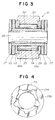
- FIG. 3 is a cross-sectional view of a roller chain incorporating the roller bearings according to Embodiment 2 of the present invention.
- FIG. 4 is a plan view of a retainer used in the roller chain shown in FIG. 3.
- 5 rollers 24 and 5 rollers 24' are alternately disposed on an outer periphery of a bush 23 whose both ends were connected to a pair of inner link plates 22, a roller 25 is attached so as to surround 5 rollers 24 and 5 rollers 24'.
- a pair of outer link plates 27 is disposed outside the inner link plates 22 and the pair of outer link plates 27 is connected to each other by means of a pin 28 that penetrates the bush 23.
- the space between the roller 25 and the bush 23 is filled with a lubricant such as grease or the like.
- the roller 25 functions as an outer ring of the roller bearings
- the plurality of rollers 24, 24' function as a rolling body of the roller bearings
- the bush 23 functions as an inner ring of the roller bearings. Therefore, the roller 25, the rollers 24, 24' and the bush 23 constitute the roller bearings.
- a substantially ring-shaped retainer 29 is disposed on each of both ends of the roller 25.
- the retainer 29 is substantially ring-shaped, and a recess portion 29b is formed on one side of the retainer 29.
- a plurality of semicircular pockets 29a in this Embodiment 5 pockets, are continuously formed in this recess portion 29b.
- the plurality of pockets 29a (5 pockets) hold and guide the respective ends of the rollers 24, as shown in FIG. 3.
- the roller 24' disposed between the rollers 24 has roller length shorter than the roller 24 whose each end is held and guided by the pocket 29a. Therefore, in the roller 24' having a shorter roller length the end of the roller 24' is not held and guided by the pocket 29a.
- rollers 24' having shorter roller length are used.
- a circumferential gap between the roller 24' having shorter roller length and the roller 24 removes the skew so that the rotation of the roller 25 is stabilized and the wear of the retainer 29 can be suppressed.
- Other points of the roller chain 21 are substantially the same as in the roller chain 11 shown in FIG. 1, and the operation and effects of the roller chain 21 are also substantially the same as in the roller chain 11. Thus, other explanation of the roller chain 21 is omitted.
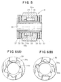
- FIG. 5 is a cross-sectional view of a roller chain incorporating the roller bearings according to Embodiment 3 of the present invention.
- FIGs. 6(A) and 6(B) are plan views of a retainer used in the roller chain shown in FIG. 5, particularly, FIG. 6(A) is a plan view of one retainer, and FIG. 6(B) is a plan view of the other retainer.
- FIG. 6(A) is a plan view of one retainer
- FIG. 6(B) is a plan view of the other retainer.
- a plurality of rollers 34 for example, 10 rollers 34 are disposed on an outer periphery of a bush 33 whose both ends were connected to a pair of inner link plates 32, a roller 35 is attached so as to surround the rollers 34.
- a pair of outer link plates 37 is disposed outside the inner link plates 32 and the pair of outer link plates 37 is connected to each other by means of a pin 38 that penetrates the bush 33.
- the space between the roller 35 and the bush 33 is filled with a lubricant such as grease or the like.
- the roller 35 functions as an outer ring of the roller bearings
- the plurality of rollers 34 function as a rolling body of the roller bearings
- the bush 33 functions as an inner ring of the roller bearings. Therefore, the roller 35, the rollers 34 and the bush 33 constitute the roller bearings.
- a substantially ring-shaped retainer 39 is disposed on each of both ends of the roller 35.
- the retainer 39 is substantially ring-shaped, and a recess portion 39b is formed on one side of the retainer 39.
- a plurality of semicircular pockets 39a, in this Embodiment 5 pockets, are formed continuously to this recess portion 39b. And the plurality of pockets 39a hold and guide the respective ends of the rollers 34.
- this retainer 39 has the same shape as the retainer 29 shown in FIG. 4, the left retainer 39 and the right retainer 39 have the respective pockets 39a whose positions or phases are shifted by 36 degrees, as shown in FIG.
- FIG. 7 is a cross-sectional view of a roller chain incorporating the roller bearings according to Embodiment 4 of the present invention.
- FIGs. 8(A), 8(B) and 8(C) are enlarged views of a circle D portion in FIG. 7, particularly, FIG. 8(A) shows the D portion in which a labyrinth R was formed between the roller 45 and the retainer 49, FIG. 8(B) shows the D portion in which annular shaped grooves 49g were formed on the retainer 49, and FIG.
- FIG. 8(C) shows the D portion in which a seal ring 49s was disposed between the roller 45 and the retainer 49.
- FIG. 9 is a cross-sectional view of a roller chain for explaining the sizes and length associated therewith of the roller chain shown in FIG. 7.
- a roller chain 41 shown in FIG. 7 a plurality of rollers 44, for example, 10 rollers 44 are disposed on an outer periphery of a bush 43 whose both ends were connected to a pair of inner link plates 42, and a roller 45 is attached so as to surround the rollers 44.
- a pair of outer link plates 47 is disposed outside the inner link plates 42 and the pair of outer link plates 47 is connected to each other by means of a pin 48 that penetrates the bush 43.
- the space between the roller 45 and the bush 43 is filled with a lubricant such as grease or the like.
- a lubricant such as grease or the like.
- the roller 45 functions as an outer ring of the roller bearings
- the plurality of rollers 44 function as a rolling body of the roller bearings
- the bush 43 functions as an inner ring of the roller bearings. Therefore, the roller 45, the rollers 44 and the bush 43 constitute the roller bearings.
- a substantially ring-shaped retainer 49 is disposed on each of both ends of the roller 45.
- the retainer 49 is substantially ring-shaped.
- a plurality of pockets 49a in this Embodiment, 10 pockets, are formed in one side of the retainer 49. And the plurality of pockets 49a hold and guide the respective ends of the rollers 44.
- the roller chain 41 shown in FIG. 7 enhances sealing properties by providing sealing means between the roller 45 and the retainer 49.
- the roller chain 41 shown in FIG. 7 there is a small gap between the roller 45 and the retainer 49 as shown in FIGs. 8 (A), 8(B) and 8(C).
- the enlarged portion shown in FIG. 8(A) shows a structure where a labyrinth R was formed between the roller 45 and the retainer 49 as sealing means.
- the enlarged portion shown in FIG. 8(B) shows a structure where three annular grooves 49g were formed on the outer periphery of the retainer 49 as sealing means.
- This annular grooves 49g are filled with grease.
- the enlarged portion shown in FIG. 8(C) shows a structure where a seal ring 49s such as an O ring or the like is disposed between the roller 45 and the retainer 49 as sealing means.
- the length L that the retainer 49 overlaps on the roller 45 is set to a distance longer than the gap S (S1 + S2) between the retainer 49 and the inner link plate 42 so that the retainer 49 is not fallen.
- the length of the roller 44 is set so that the roller 44 does not come out of the pocket 49a.
- Other points of the roller chain 41 are substantially the same as in the roller chain 11 shown in FIG. 1, and the operation and effects of the roller chain 41 are also substantially the same as in the roller chain 11. Thus, other explanation of the roller chain 41 is omitted.
- FIG. 10 is a cross-sectional view of a roller chain incorporating the roller bearings according to Embodiment 5 of the present invention.
- a roller chain 51 shown in FIG. 10 two rows of rollers 54, 54 for example, 10 rollers 54 each are disposed on an outer periphery of a bush 53 whose both ends were connected to a pair of inner link plates 52, and a roller 55 is attached so as to surround the two rows of rollers 54, 54.
- a pair of outer link plates 57 is disposed outside the inner link plates 52 and the pair of outer link plates 57 is connected to each other by means of a pin 58 that penetrates the bush 53.
- the space between the roller 55 and the bush 53 is filled with a lubricant such as grease or the like.
- a lubricant such as grease or the like.
- the roller 55 functions as an outer ring of the roller bearings
- the two rows of rollers 54, 54 function as a rolling body of the roller bearings
- the bush 53 functions as an inner ring of the roller bearings. Therefore, the roller 55, the two rows of rollers 54, 54 and the bush 53 constitute the roller bearings. Lengths of two rows of rollers 54, 54 may be the same or different from each other.
- a plurality of rollers 64 for example, 10 rollers 64 each are disposed on an outer periphery of a bush 63 whose both ends were connected to a pair of inner link plates 62, and a roller 65 is attached so as to surround the rollers 64.
- the roller 65 has inner and outer peripheries each having a straight cylindrical shape.
- a pair of outer link plates 67 is disposed outside the inner link plates 62 and the pair of outer link plates 67 is connected to each other by means of a pin 68 that penetrates the bush 63.
- the space between the roller 65 and the bush 63 is filled with a lubricant such as grease or the like.
- the roller 65 functions as an outer ring of the roller bearings
- the rollers 64 function as a rolling body of the roller bearings
- the bush 63 functions as an inner ring of the roller bearings. Therefore, the roller 65, the rollers 64 and the bush 63 constitute the roller bearings.
- a substantially ring-shaped retainer 69 is disposed on each of both ends of the roller 65.
- the retainer 69 is substantially ring-shaped.
- a plurality of pockets 69a in this Embodiment, 10 pockets, each having a rectangular shape in a plan view are formed in one side of the retainer. And the respective pockets 69a hold and guide the respective ends of the rollers 64.
- Other points of the roller chain 61 are substantially the same as in the roller chain 11 shown in FIG. 1, and the operation and effects of the roller chain 61 are also substantially the same as in the roller chain 11. Thus, other explanation of the roller chain 61 is omitted.
- FIG. 13 is a cross-sectional view of a roller chain incorporating the roller bearings according to Embodiment 7 of the present invention.
- FIGs. 14(A) and 14(B) show a retainer used in the roller chain shown in FIG. 13, particularly, FIG. 14(A) is a cross-sectional view thereof and FIG. 14(B) is a plan view thereof.
- FIG. 14(A) is a cross-sectional view thereof
- FIG. 14(B) is a plan view thereof.
- rollers 74 for example, 10 rollers 74 each are disposed on an outer periphery of a bush 73 whose both ends were connected to a pair of inner link plates 72, and a roller 75 is attached so as to surround the rollers 74.
- the roller 75 has inner and outer peripheries each having a straight cylindrical shape.
- a pair of outer link plates 77 is disposed outside the inner link plates 72 and the pair of outer link plates 77 is connected to each other by means of a pin 78 that penetrates the bush 73.
- the space between the roller 75 and the bush 73 is filled with a lubricant such as grease or the like.
- the roller 75 functions as an outer ring of the roller bearings
- the rollers 74 function as a rolling body of the roller bearings
- the bush 73 functions as an inner ring of the roller bearings. Therefore, the roller 75, the rollers 74 and the bush 73 constitute the roller bearings.
- a substantially ring-shaped retainer 79 is disposed on each of both ends of the roller 75.
- the retainer 79 is substantially ring-shaped.
- a plurality of pockets 79a in this Embodiment, 10 pockets, each having a rectangular shape in a plan view are formed in one side of the retainer 79. And the respective pockets 79a hold and guide the respective ends of the rollers 74.
- FIG. 15 is a cross-sectional view of a roller chain incorporating the roller bearings according to Embodiment 8 of the present invention.
- FIG. 16 is a plan view of a retainer used in the roller chain shown in FIG. 15.
- a roller chain 81 shown in FIG. 15 a plurality of rollers 84, for example, 10 rollers 84 each are disposed on an outer periphery of a bush 83 whose both ends were connected to a pair of inner link plates 82, and a roller 85 is attached so as to surround the rollers 84.
- Each of the rollers 84 has small diameter portions 84a on the both ends.
- the roller 85 has inner and outer peripheries each having a straight cylindrical shape. Further, a pair of outer link plates 87 is disposed outside the inner link plates 82 and the pair of outer link plates 87 is connected to each other by means of a pin 88 that penetrates the bush 83. Further, the space between the roller 85 and the bush 83 is filled with a lubricant such as grease or the like.
- the roller 85 functions as an outer ring of the roller bearings
- the rollers 84 function as a rolling body of the roller bearings
- the bush 83 functions as an inner ring of the roller bearings. Therefore, the roller 85, the rollers 84 and the bush 83 constitute the roller bearings.
- FIG. 17 is a cross-sectional view of a roller chain incorporating the roller bearings according to Embodiment 9 of the present invention.
- FIGs. 18(A) and 18(B) show a thrust bearings receiving plate used in a roller chain shown in FIG. 17, particularly, FIG. 18(A) is a cross-sectional view of the thrust bearings receiving plate and FIG. 18(B) is a plan view thereof.
- FIGs. 19(A) and 19(B) show a retainer used in the roller chain shown in FIG. 17, particularly, FIG.
- a substantially ring-shaped retainer 99 is disposed on each of both ends of the roller 95.
- the retainer 99 is substantially ring-shaped.
- a plurality of pockets 99a in this Embodiment, 10 pockets each having a rectangular shape in a plan view are on one side of the retainer 99. Since each pocket 99a holds and guides an end of each roller 94.
- the roller chain 91 shown in FIG. 17 include thrust bearings receiving plates 96 (one shown in FIGs. 18(A) and 18(B)). Each thrust bearings receiving plate 96 is intervened between the ends of the roller 95 and retainer 99 and the end of the inner link plate 92.
- this thrust bearings receiving plate 96 increases the contact area and the contact pressure is decreased when a thrust load is applied to the roller 95. Accordingly, wear of the retainer 99 and thrust bearings receiving plate 96 can be suppressed.
- Other points of the roller chain 91 are substantially the same as in the roller chain 11 shown in FIG. 1, and the operation and effects of the roller chain 91 are also substantially the same as in the roller chain 11. Thus, other explanation of the roller chain 91 is omitted.
- FIG. 20 is a cross-sectional view of a roller chain incorporating the roller bearings according to Embodiment 10 of the present invention.
- FIGs. 21(A) and 21(B) show a retainer used in the roller chain shown in FIG. 20, particularly, FIG. 21(A) is a cross-sectional view of the retainer and FIG. 21(B) is a plan view thereof.
- a roller chain 111 shown in FIG. 20 is different from the roller chain 11 shown in FIG. 1 only in that the roller chain 111 in FIG. 20 is one where the bush 13 is not used in the roller chain 11 in FIG. 1, that is a bushless chain.
- roller chain 111 a pair of outer link plates 117 is connected to both ends of a pin 118 onto which a pair of inner link plates 112 was fitted.
- a plurality of rollers 114 for example, 10 rollers 114 each are disposed on an outer periphery of the pin 118, and a roller 115 is attached so as to surround the rollers 114. Further, the space between the roller 115 and the pin 118 is filled with a lubricant such as grease or the like.
- the roller 115 functions as an outer ring of the roller bearings
- the rollers 114 function as a rolling body of the roller bearings
- the pin 118 functions as an inner ring of the roller bearings. Therefore, the roller 115, the rollers 114 and the pin 118 constitute the roller bearings.
- a substantially ring-shaped retainer 119 is disposed on each of both ends of the roller 115.
- the retainer 119 is substantially ring-shaped.
- a recess portion 119b is formed on one side of each retainer 119 and a plurality of pockets 119a, in this Embodiment, 10 pockets each having a continuous semicircular shape in a plan view are formed continuously to the recess portion 119b.
- Each of the pockets 119a holds and guides an end of each roller 114.
- Other points of the roller chain 111 are substantially the same as in the roller chain 11 shown in FIG. 1, and the operation and effects of the roller chain 111 are also substantially the same as in the roller chain 11. Thus, other explanation of the roller chain 111 is omitted.
Landscapes
- Engineering & Computer Science (AREA)
- General Engineering & Computer Science (AREA)
- Mechanical Engineering (AREA)
- Rolling Contact Bearings (AREA)
- Rollers For Roller Conveyors For Transfer (AREA)
- Chain Conveyers (AREA)
Applications Claiming Priority (2)
| Application Number | Priority Date | Filing Date | Title |
|---|---|---|---|
| JP2001034283 | 2001-02-09 | ||
| JP2001034283A JP3563354B2 (ja) | 2001-02-09 | 2001-02-09 | ころ軸受を組み込んだローラチェーン |
Publications (2)
| Publication Number | Publication Date |
|---|---|
| EP1231410A1 true EP1231410A1 (de) | 2002-08-14 |
| EP1231410B1 EP1231410B1 (de) | 2006-02-01 |
Family
ID=18897917
Family Applications (1)
| Application Number | Title | Priority Date | Filing Date |
|---|---|---|---|
| EP02002856A Expired - Lifetime EP1231410B1 (de) | 2001-02-09 | 2002-02-08 | Rollenwälzlager und die Rollenwälzlager aufweisende Kette |
Country Status (8)
| Country | Link |
|---|---|
| US (1) | US6742935B2 (de) |
| EP (1) | EP1231410B1 (de) |
| JP (1) | JP3563354B2 (de) |
| KR (1) | KR100470286B1 (de) |
| CN (1) | CN1205421C (de) |
| DE (1) | DE60208935T2 (de) |
| HK (1) | HK1047968B (de) |
| TW (1) | TW509754B (de) |
Cited By (2)
| Publication number | Priority date | Publication date | Assignee | Title |
|---|---|---|---|---|
| CN103322126A (zh) * | 2013-07-02 | 2013-09-25 | 上海松科机械自动化技术有限公司 | Y型双侧滚子推拉链条 |
| CN113800009A (zh) * | 2021-08-12 | 2021-12-17 | 曹立勇 | 一种用于船舶的锚链筒盖机构 |
Families Citing this family (33)
| Publication number | Priority date | Publication date | Assignee | Title |
|---|---|---|---|---|
| JP3719963B2 (ja) * | 2001-08-09 | 2005-11-24 | 株式会社椿本チエイン | チェーン |
| DE10256086A1 (de) * | 2002-11-29 | 2004-06-17 | Leybold Vakuum Gmbh | Kugellager und mit einem Lager dieser Art ausgerüstete Vakuumpumpe |
| DE10359922A1 (de) * | 2003-12-18 | 2005-08-04 | Horst Weidner Gmbh | Rollenkette |
| TWI274640B (en) * | 2004-04-08 | 2007-03-01 | Fabworx Solutions Inc | Hub assembly for robotic arm having pin spacers |
| EP1745227A1 (de) * | 2004-05-11 | 2007-01-24 | Timken US Corporation | Schrägstirnradanordnung |
| JP4255969B2 (ja) * | 2006-12-05 | 2009-04-22 | 株式会社椿本チエイン | ベアリングローラチェーン |
| JP4455608B2 (ja) * | 2007-03-20 | 2010-04-21 | 株式会社椿本チエイン | 円筒ころ型ローラチェーン |
| KR100863994B1 (ko) * | 2007-05-01 | 2008-10-16 | 김삼석 | 자전거 |
| JP5770972B2 (ja) * | 2009-04-22 | 2015-08-26 | Ntn株式会社 | ニードル軸受及びニードル軸受装置 |
| CN101922505A (zh) * | 2010-09-09 | 2010-12-22 | 天津宏九地工程机械有限公司 | 内外圈可相对移动的向心滚柱轴承 |
| US8814439B2 (en) * | 2010-10-29 | 2014-08-26 | David P. SEBELIUS | Bearing assembly, clutch assembly and constant velocity transmission |
| JP5637871B2 (ja) * | 2011-01-13 | 2014-12-10 | 株式会社椿本チエイン | コンベヤチェーン |
| CN102345669B (zh) * | 2011-06-24 | 2013-02-20 | 无锡杰思物流设备有限公司 | 滚针滚轮结构 |
| CN103133537A (zh) * | 2011-11-28 | 2013-06-05 | 思考电机(上海)有限公司 | 推力轴承 |
| US9091250B2 (en) * | 2012-05-02 | 2015-07-28 | United Technologies Corporation | Ultra high efficiency low friction drive chain for wind turbine applications |
| US8933576B2 (en) | 2012-05-02 | 2015-01-13 | United Technologies Corporation | Hybrid friction wheel gearbox drivetrain for wind turbine applications |
| US8598725B1 (en) | 2012-06-11 | 2013-12-03 | United Technologies Corporation | Utilizing flux controllable PM electric machines for wind turbine applications |
| US9033586B2 (en) * | 2013-08-13 | 2015-05-19 | Schaeffler Technologies AG & Co. KG | Two piece cage for a needle bearing |
| JP5675923B1 (ja) * | 2013-09-19 | 2015-02-25 | 株式会社椿本チエイン | ベアリングローラチェーン |
| DE112014000050B4 (de) * | 2014-03-27 | 2016-11-17 | Komatsu Ltd. | Dreheinheit für ein Arbeitsfahrzeug und Verfahren zu deren Herstellung |
| DE102014210751A1 (de) * | 2014-06-05 | 2015-12-17 | Schaeffler Technologies AG & Co. KG | Wälzlager, insbesondere Rillenkugellager, mit Führungshilfen für Wälzkörper |
| KR20170021340A (ko) | 2014-07-30 | 2017-02-27 | 코요 베어링즈 노쓰 아메리카 엘엘씨 | 리테이너 링이 있는 롤러 베어링 조립체 |
| US9416848B2 (en) * | 2014-12-10 | 2016-08-16 | U.S. Tsubaki, Inc. | Pin-roller chain |
| US9151359B1 (en) * | 2014-12-10 | 2015-10-06 | U.S. Tsubaki, Inc. | Pin-roller chain |
| JP6790517B2 (ja) * | 2016-07-06 | 2020-11-25 | 株式会社ジェイテクト | 円すいころ軸受 |
| CN106246717A (zh) * | 2016-08-12 | 2016-12-21 | 安徽江淮汽车股份有限公司 | 一种滚针衬套及其辅装结构 |
| CN106246718A (zh) * | 2016-08-12 | 2016-12-21 | 安徽江淮汽车股份有限公司 | 一种滚针衬套及其辅装结构 |
| CN106050909B (zh) * | 2016-08-12 | 2018-04-06 | 安徽江淮汽车集团股份有限公司 | 一种滚针衬套及其辅装结构 |
| CN106241204A (zh) * | 2016-09-12 | 2016-12-21 | 周杰 | 一种免润滑输送链 |
| KR102147766B1 (ko) * | 2019-09-19 | 2020-08-25 | 강동관 | 체인 콘베어의 슬림형 체인 |
| KR102172313B1 (ko) * | 2019-10-23 | 2020-11-02 | 신태식 | 세차설비의 차량 이송장치 |
| CN112061687B (zh) * | 2020-09-07 | 2022-03-04 | 福建省铁拓机械股份有限公司 | 一种斗式提升机底部密封设备 |
| CN115638183B (zh) * | 2022-11-07 | 2025-10-21 | 中机洛阳精密装备科技股份有限公司 | 一种特殊结构的煤矿机械设备主轴用剖分轴承 |
Citations (12)
| Publication number | Priority date | Publication date | Assignee | Title |
|---|---|---|---|---|
| US681793A (en) * | 1901-03-21 | 1901-09-03 | John Hutchison | Roller-bearing. |
| US3362762A (en) * | 1965-08-18 | 1968-01-09 | Federal Mogul Corp | Roller bearing assembly with rollerengaging spacers |
| US3711911A (en) * | 1970-11-25 | 1973-01-23 | Textron Inc | Method of roller bearing retention and assembly |
| JPS624122A (ja) | 1985-06-26 | 1987-01-10 | Tsubakimoto Chain Co | ロ−ラチエ−ン |
| JPH027219A (ja) | 1988-06-24 | 1990-01-11 | Mitsubishi Electric Corp | 磁気ヘッド支持板 |
| US4915511A (en) * | 1985-06-26 | 1990-04-10 | Tsubakimoto Chain Co. | Roller chain |
| JPH0478523A (ja) | 1990-07-20 | 1992-03-12 | Matsushita Electric Works Ltd | 三次元形状の形成方法 |
| JPH0712327A (ja) | 1991-12-03 | 1995-01-17 | Roland Steinmaier | ディーゼル燃料及び水の乳化のための乳化装置 |
| US5823686A (en) * | 1995-08-07 | 1998-10-20 | Tsubakimoto Chain Co. | Chain with oilless antifriction bearing |
| US6102573A (en) * | 1998-04-27 | 2000-08-15 | Tsubakimoto Chain Co. | Roller chain |
| JP2000240072A (ja) | 1999-02-24 | 2000-09-05 | Takenaka Komuten Co Ltd | 免震装置の設置方法及び設置構造 |
| US6179474B1 (en) * | 1997-11-21 | 2001-01-30 | The Torrington Company | High capacity roller bearing |
Family Cites Families (10)
| Publication number | Priority date | Publication date | Assignee | Title |
|---|---|---|---|---|
| US1609618A (en) * | 1926-12-07 | Roller-bearing retainer | ||
| US745198A (en) * | 1901-01-02 | 1903-11-24 | Gustavus E Strauss | Roller-bearing. |
| US2540283A (en) * | 1946-12-05 | 1951-02-06 | Int Harvester Co | Roller bearing |
| US2696412A (en) * | 1951-02-01 | 1954-12-07 | Curtiss Wright Corp | Roller bearing construction |
| US3206263A (en) * | 1962-10-12 | 1965-09-14 | Gen Motors Corp | Cage for antifriction bearings |
| JPH02145323A (ja) | 1988-11-28 | 1990-06-04 | Tosoh Corp | 衝撃吸収材 |
| US5630669A (en) * | 1994-07-12 | 1997-05-20 | Craft Bearing Company, Inc. | Split bearing, cage for split or non-split bearing and method of cutting a member of a split bearing |
| US5660485A (en) * | 1996-06-20 | 1997-08-26 | The Torrington Company | Modular retainer assembly |
| JP3336330B2 (ja) | 1997-03-10 | 2002-10-21 | 株式会社椿本チエイン | 円筒コロを内装したローラを有するコンベヤチェーン |
| JP3410354B2 (ja) | 1998-02-26 | 2003-05-26 | 東京瓦斯株式会社 | 既設管路の修理工法 |
-
2001
- 2001-02-09 JP JP2001034283A patent/JP3563354B2/ja not_active Expired - Fee Related
-
2002
- 2002-02-06 TW TW091102048A patent/TW509754B/zh active
- 2002-02-07 KR KR10-2002-0006990A patent/KR100470286B1/ko not_active Expired - Fee Related
- 2002-02-08 EP EP02002856A patent/EP1231410B1/de not_active Expired - Lifetime
- 2002-02-08 DE DE60208935T patent/DE60208935T2/de not_active Expired - Lifetime
- 2002-02-08 US US10/071,970 patent/US6742935B2/en not_active Expired - Fee Related
- 2002-02-09 CN CNB021183058A patent/CN1205421C/zh not_active Expired - Fee Related
- 2002-12-30 HK HK02109421.8A patent/HK1047968B/zh not_active IP Right Cessation
Patent Citations (12)
| Publication number | Priority date | Publication date | Assignee | Title |
|---|---|---|---|---|
| US681793A (en) * | 1901-03-21 | 1901-09-03 | John Hutchison | Roller-bearing. |
| US3362762A (en) * | 1965-08-18 | 1968-01-09 | Federal Mogul Corp | Roller bearing assembly with rollerengaging spacers |
| US3711911A (en) * | 1970-11-25 | 1973-01-23 | Textron Inc | Method of roller bearing retention and assembly |
| JPS624122A (ja) | 1985-06-26 | 1987-01-10 | Tsubakimoto Chain Co | ロ−ラチエ−ン |
| US4915511A (en) * | 1985-06-26 | 1990-04-10 | Tsubakimoto Chain Co. | Roller chain |
| JPH027219A (ja) | 1988-06-24 | 1990-01-11 | Mitsubishi Electric Corp | 磁気ヘッド支持板 |
| JPH0478523A (ja) | 1990-07-20 | 1992-03-12 | Matsushita Electric Works Ltd | 三次元形状の形成方法 |
| JPH0712327A (ja) | 1991-12-03 | 1995-01-17 | Roland Steinmaier | ディーゼル燃料及び水の乳化のための乳化装置 |
| US5823686A (en) * | 1995-08-07 | 1998-10-20 | Tsubakimoto Chain Co. | Chain with oilless antifriction bearing |
| US6179474B1 (en) * | 1997-11-21 | 2001-01-30 | The Torrington Company | High capacity roller bearing |
| US6102573A (en) * | 1998-04-27 | 2000-08-15 | Tsubakimoto Chain Co. | Roller chain |
| JP2000240072A (ja) | 1999-02-24 | 2000-09-05 | Takenaka Komuten Co Ltd | 免震装置の設置方法及び設置構造 |
Non-Patent Citations (1)
| Title |
|---|
| PATENT ABSTRACTS OF JAPAN vol. 011, no. 172 (M - 595) 3 June 1987 (1987-06-03) * |
Cited By (3)
| Publication number | Priority date | Publication date | Assignee | Title |
|---|---|---|---|---|
| CN103322126A (zh) * | 2013-07-02 | 2013-09-25 | 上海松科机械自动化技术有限公司 | Y型双侧滚子推拉链条 |
| CN103322126B (zh) * | 2013-07-02 | 2015-11-18 | 上海松科快换自动化股份有限公司 | Y型双侧滚子推拉链条 |
| CN113800009A (zh) * | 2021-08-12 | 2021-12-17 | 曹立勇 | 一种用于船舶的锚链筒盖机构 |
Also Published As
| Publication number | Publication date |
|---|---|
| EP1231410B1 (de) | 2006-02-01 |
| DE60208935T2 (de) | 2006-10-19 |
| TW509754B (en) | 2002-11-11 |
| JP3563354B2 (ja) | 2004-09-08 |
| KR100470286B1 (ko) | 2005-02-05 |
| US20020110297A1 (en) | 2002-08-15 |
| HK1047968B (zh) | 2005-11-18 |
| KR20020066192A (ko) | 2002-08-14 |
| HK1047968A1 (en) | 2003-03-14 |
| DE60208935D1 (de) | 2006-04-13 |
| CN1374463A (zh) | 2002-10-16 |
| JP2002235812A (ja) | 2002-08-23 |
| CN1205421C (zh) | 2005-06-08 |
| US6742935B2 (en) | 2004-06-01 |
Similar Documents
| Publication | Publication Date | Title |
|---|---|---|
| EP1231410A1 (de) | Rollenwälzlager und die Rollenwälzlager aufweisende Kette | |
| US7090405B2 (en) | Tapered roller bearings and gear shaft support devices | |
| CN103097753B (zh) | 滚动轴承用保持架以及滚动轴承 | |
| US7033082B2 (en) | Angular contact ball bearing and spindle device | |
| CN100400907C (zh) | 用于压缩机皮带轮的转动支撑装置 | |
| KR20110071928A (ko) | 부시타입 베어링 및 그 제조방법 | |
| EP0928909B1 (de) | Getriebe für Kraftfahrzeuge und Lager hierfür | |
| KR102074125B1 (ko) | 볼 베어링, 및 공작 기계용 주축 장치 | |
| KR20180041127A (ko) | 앵귤러 콘택트 볼 베어링 | |
| JP4288903B2 (ja) | ボールねじ装置 | |
| JP2005133818A (ja) | 転がり軸受 | |
| JP2003042160A (ja) | アンギュラ玉軸受及び主軸装置 | |
| JP2003247552A (ja) | 転がり玉軸受用冠形保持器の製造方法、転がり玉軸受用冠形保持器の製造に用いられる金型、転がり玉軸受用冠形保持器、転がり玉軸受 | |
| CN112824693A (zh) | 推力滚子轴承 | |
| JPH0791452A (ja) | 転がり軸受 | |
| JP4366580B2 (ja) | 玉軸受用保持器 | |
| JP4013030B2 (ja) | アンギュラ玉軸受 | |
| JP2002227938A (ja) | ローラチェーン | |
| JPH07103243A (ja) | 転がり軸受 | |
| US20250283508A1 (en) | Bearing unit with retention cage | |
| JP2002235751A (ja) | 転がり軸受 | |
| CA1223434A (en) | Universal joint cross member trunnion and method | |
| TWI704299B (zh) | 滾珠軸承及工具機用主軸裝置 | |
| JP2012132506A (ja) | 円筒ころ軸受及び工作機械用主軸装置 | |
| JP2008088994A (ja) | スラストころ軸受用保持器の製造方法 |
Legal Events
| Date | Code | Title | Description |
|---|---|---|---|
| PUAI | Public reference made under article 153(3) epc to a published international application that has entered the european phase |
Free format text: ORIGINAL CODE: 0009012 |
|
| AK | Designated contracting states |
Kind code of ref document: A1 Designated state(s): AT BE CH CY DE DK ES FI FR GB GR IE IT LI LU MC NL PT SE TR |
|
| AX | Request for extension of the european patent |
Free format text: AL;LT;LV;MK;RO;SI |
|
| 17P | Request for examination filed |
Effective date: 20020913 |
|
| AKX | Designation fees paid |
Designated state(s): DE GB IT |
|
| RAP1 | Party data changed (applicant data changed or rights of an application transferred) |
Owner name: TSUBAKIMOTO CHAIN CO. |
|
| 17Q | First examination report despatched |
Effective date: 20040906 |
|
| GRAP | Despatch of communication of intention to grant a patent |
Free format text: ORIGINAL CODE: EPIDOSNIGR1 |
|
| GRAS | Grant fee paid |
Free format text: ORIGINAL CODE: EPIDOSNIGR3 |
|
| GRAA | (expected) grant |
Free format text: ORIGINAL CODE: 0009210 |
|
| AK | Designated contracting states |
Kind code of ref document: B1 Designated state(s): DE GB IT |
|
| REG | Reference to a national code |
Ref country code: GB Ref legal event code: FG4D |
|
| REF | Corresponds to: |
Ref document number: 60208935 Country of ref document: DE Date of ref document: 20060413 Kind code of ref document: P |
|
| PLBE | No opposition filed within time limit |
Free format text: ORIGINAL CODE: 0009261 |
|
| STAA | Information on the status of an ep patent application or granted ep patent |
Free format text: STATUS: NO OPPOSITION FILED WITHIN TIME LIMIT |
|
| 26N | No opposition filed |
Effective date: 20061103 |
|
| PGFP | Annual fee paid to national office [announced via postgrant information from national office to epo] |
Ref country code: GB Payment date: 20090204 Year of fee payment: 8 |
|
| PGFP | Annual fee paid to national office [announced via postgrant information from national office to epo] |
Ref country code: IT Payment date: 20090212 Year of fee payment: 8 |
|
| GBPC | Gb: european patent ceased through non-payment of renewal fee |
Effective date: 20100208 |
|
| PG25 | Lapsed in a contracting state [announced via postgrant information from national office to epo] |
Ref country code: IT Free format text: LAPSE BECAUSE OF NON-PAYMENT OF DUE FEES Effective date: 20100208 Ref country code: GB Free format text: LAPSE BECAUSE OF NON-PAYMENT OF DUE FEES Effective date: 20100208 |
|
| PGFP | Annual fee paid to national office [announced via postgrant information from national office to epo] |
Ref country code: DE Payment date: 20130206 Year of fee payment: 12 |
|
| REG | Reference to a national code |
Ref country code: DE Ref legal event code: R119 Ref document number: 60208935 Country of ref document: DE |
|
| REG | Reference to a national code |
Ref country code: DE Ref legal event code: R119 Ref document number: 60208935 Country of ref document: DE Effective date: 20140902 |
|
| PG25 | Lapsed in a contracting state [announced via postgrant information from national office to epo] |
Ref country code: DE Free format text: LAPSE BECAUSE OF NON-PAYMENT OF DUE FEES Effective date: 20140902 |