EP1231497A2 - Astronomisches Teleskop - Google Patents
Astronomisches Teleskop Download PDFInfo
- Publication number
- EP1231497A2 EP1231497A2 EP02290307A EP02290307A EP1231497A2 EP 1231497 A2 EP1231497 A2 EP 1231497A2 EP 02290307 A EP02290307 A EP 02290307A EP 02290307 A EP02290307 A EP 02290307A EP 1231497 A2 EP1231497 A2 EP 1231497A2
- Authority
- EP
- European Patent Office
- Prior art keywords
- spherical
- lenses
- lens
- convex
- corrector
- Prior art date
- Legal status (The legal status is an assumption and is not a legal conclusion. Google has not performed a legal analysis and makes no representation as to the accuracy of the status listed.)
- Withdrawn
Links
- 230000003287 optical effect Effects 0.000 claims abstract description 36
- 230000004075 alteration Effects 0.000 claims abstract description 33
- 238000012937 correction Methods 0.000 claims abstract description 26
- 239000011521 glass Substances 0.000 claims description 11
- 241000219739 Lens Species 0.000 description 85
- 241000581464 Dactyloscopidae Species 0.000 description 6
- 230000001902 propagating effect Effects 0.000 description 6
- 241001639412 Verres Species 0.000 description 3
- 235000021183 entrée Nutrition 0.000 description 2
- 230000004907 flux Effects 0.000 description 2
- 206010010071 Coma Diseases 0.000 description 1
- 235000014647 Lens culinaris subsp culinaris Nutrition 0.000 description 1
- 201000009310 astigmatism Diseases 0.000 description 1
- 238000010586 diagram Methods 0.000 description 1
Images





Classifications
-
- G—PHYSICS
- G02—OPTICS
- G02B—OPTICAL ELEMENTS, SYSTEMS OR APPARATUS
- G02B17/00—Systems with reflecting surfaces, with or without refracting elements
- G02B17/08—Catadioptric systems
- G02B17/0852—Catadioptric systems having a field corrector only
-
- G—PHYSICS
- G02—OPTICS
- G02B—OPTICAL ELEMENTS, SYSTEMS OR APPARATUS
- G02B17/00—Systems with reflecting surfaces, with or without refracting elements
- G02B17/08—Catadioptric systems
- G02B17/0804—Catadioptric systems using two curved mirrors
- G02B17/0808—Catadioptric systems using two curved mirrors on-axis systems with at least one of the mirrors having a central aperture
-
- G—PHYSICS
- G02—OPTICS
- G02B—OPTICAL ELEMENTS, SYSTEMS OR APPARATUS
- G02B23/00—Telescopes, e.g. binoculars; Periscopes; Instruments for viewing the inside of hollow bodies; Viewfinders; Optical aiming or sighting devices
- G02B23/02—Telescopes, e.g. binoculars; Periscopes; Instruments for viewing the inside of hollow bodies; Viewfinders; Optical aiming or sighting devices involving prisms or mirrors
- G02B23/06—Telescopes, e.g. binoculars; Periscopes; Instruments for viewing the inside of hollow bodies; Viewfinders; Optical aiming or sighting devices involving prisms or mirrors having a focussing action, e.g. parabolic mirror
-
- G—PHYSICS
- G02—OPTICS
- G02B—OPTICAL ELEMENTS, SYSTEMS OR APPARATUS
- G02B27/00—Optical systems or apparatus not provided for by any of the groups G02B1/00 - G02B26/00, G02B30/00
- G02B27/0025—Optical systems or apparatus not provided for by any of the groups G02B1/00 - G02B26/00, G02B30/00 for optical correction, e.g. distorsion, aberration
Definitions
- the present invention relates to a telescope astronomical.
- Figure 1 is a schematic representation of a optical system as implemented in a telescope astronomical known as of Cassegrain of the prior art.
- the system optic is arranged so that the luminous flux 1 from an infinite object, transmitted in one direction coming from the left of Figure 1, is reflected by a parabolic mirror 2, called primary mirror.
- the beam as well reflected then falls on a convex hyperbolic mirror 3, says secondary mirror, one of the focal points of which coincides with that of parabolic mirror 2.
- the beam reflected by the mirror secondary 3 forms an image at the second focal point F of the mirror hyperbolic.
- the primary mirror 2 being pierced in its center, the second focus of the hyperbolic mirror 3 happens to be in withdrawal from the tube carrying the primary mirror 2.
- This foyer 4 is called Foyer de Cassegrain.
- the Cassegrain telescope can be used as a reflector with a wide opening.
- aberrations outside the optical axis reduce then considerably the useful field angle. Indeed, from a field of the order of 1 °, the aberrations of coma and astigmatism are very important.
- the objective of the present invention is to provide a astronomical telescope simple in its design and in its operating mode, carried out with spherical mirrors and providing a wide field of view without the aberration problems encountered by the telescope of Cassegrain.
- the optical correction system of aberrations includes at least four lenses correcting aberrations.
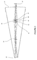
- FIG. 2 is therefore a schematic representation of a first embodiment of the telescope, according to the invention.
- the telescope is an astronomical telescope whose the reflecting mirrors 16, 17 have a spherical surface and which have been associated with an 18-21 optical system from correction of aberrations.
- These mirrors 16, 17 are therefore easy to polish optically but have an aberration infinitely important spherical. It is then necessary to correct this aberration.
- the optical correction system of aberrations includes two spherical correctors, each comprising two lenses.
- These 18-21 lenses are spherical lenses which correct aberrations on the one hand spherical generated by the first 16 and second 17 mirrors spherical reflectors, respectively concave and convex, and on the other hand the chromatic aberrations generated by the 18-21 lenses themselves.
- the optical system is arranged so that a flow luminous, coming from a celestial object placed at infinity and is propagating either along the optical axis, 0, or off the axis optical with a field angle of 0.5 °, 0 ', is transmitted in a direction coming from the left of Figure 2 and then finds reflected by a concave spherical mirror 16, says primary mirror.
- the half-diameter of the primary mirror 16 is 200 mm. This mirror 16 is pierced at its center. The beam thus reflected falls on a convex spherical mirror 17, says secondary mirror.
- the half-diameter of the secondary mirror 17 is 98 mm.
- the beam reflected by the secondary mirror 17 then falls on an optical correction system of aberrations comprising two spherical correctors.
- Each spherical corrector comprises a first 18, 20 and a second 19, 21 spherical lenses.
- the first one spherical lens 18 of the first corrector has a face 4 concave input for the light beam and the second spherical lens 19 of the first corrector has a face 7 convex outlet.
- the half diameter of the lenses spherical 18 and 19 of the first corrector is 63 mm. To the output of the first spherical corrector, the light beam falls on the second spherical corrector.
- the first lens spherical 20 of the second corrector has an entry face 8 convex for a light beam and the second lens spherical 21 of the second corrector has a face of exit 11 concave.
- Half the diameter of spherical lenses 20 and 21 of the second corrector is 40 mm.
- Lentils spherical 18-21 are formed of a common glass having a refractive index of the order of 1.5, for example a glass of type Schott BK7 (Registered trademark of the company Schott) of which the refractive index is 1.517. It is known that this commercial reference can be replaced by a reference equivalent.
- the 18-21 lenses are separated by a space air.
- the image carried by the propagating light beam along the optical axis 0 is formed at focus 12.
- the image carried by the light beam propagating outside the optical axis with a field angle of 0.5 ° forms at focus 12 '.
- the configuration according to Table 1 is chosen in which the number (No) designates a diopter or a medium (in the order of propagation of the light) and the other columns provide the characteristics of the diopters, the lengths being expressed in millimeters with exponential notation for large values (eg: e + 8 meaning 10 8 ): No.
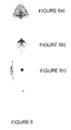
- Figure 6 is a schematic representation of the image of a circular source, in the center of the focal plane of the telescope according to Figure 2 and Table 1, depending on the angle of incidence of the light beam relative to the axis optical.
- Figure 6a) was obtained for an angle of view wide, of the order of 0.5 °.
- Figure 6b) was obtained for a field of view on the order of 0.35 ° and
- Figure 6c) has been obtained for a light beam propagating according to the optical axis.
- the image in Fig. 6c) therefore makes it possible to appreciate the aberration corrections made to the aberration spherical resulting from the use of mirrors spherical reflectors 16 and 17, according to the invention.
- the aberrations are well corrected in the visible and particularly for a source emitting between 0.486 ⁇ m and 0.656 ⁇ m.
- Figures 3 to 5 are schematic representations of three different configurations of a second mode of realization of the telescope according to the invention. These three configurations have in common, with the configuration according to first embodiment, that the astronomical telescope includes two reflective mirrors with spherical surfaces with which an optical correction system is associated aberrations. So, a luminous flux, coming from an object celestial placed at infinity and propagating either along the axis optics of the telescope, or off the optical axis with an angle field strength of 0.5 °, is transmitted in a direction from the left of Figures 3 to 5 and is then reflected by a concave spherical mirror 31, called primary mirror.
- a concave spherical mirror 31 called primary mirror.
- Half diameter of the primary mirror 31 is 200 mm and corresponds thus to that of the primary mirror 16 according to the first mode of production.
- the mirror 31 is pierced at its center.
- the beam thus reflected falls on a convex spherical mirror 32, says secondary mirror.
- the half-diameter of the secondary mirror 32 is less than half the half diameter of the mirror secondary 17 of the first embodiment, i.e. less than 50 mm.
- the half-diameter of the secondary mirror 32 is even less than 40 mm, like tables 2 to 5 indicate.
- the beam reflected by the secondary mirror 32 is focused by the latter in such a way that the image carried by the light beam is formed at a short distance before a field lens 33 disposed between the secondary mirror and the optical correction system, referenced 34, 35 or 36 depending on the particular configuration.
- the beam coming out of the optical correction system finally falls on a lens field correction 37 at the exit of which forms at new image carried by the light beam.
- the lens of field 33 and the field correction lens 37 have each half a diameter of about 20 mm.
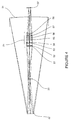
- Figure 3 is therefore a schematic representation of a first configuration of the second embodiment of the telescope of the invention.
- the optical aberration correction system referenced here 34, includes five lenses 41 to 45 which are lenses spherical and which correct spherical aberrations generated by the first 31 and the second 32 reflective mirrors spherical, respectively concave and convex, on the one hand, and the chromatic aberrations generated by the lenses 41 to 45 themselves, on the other hand.
- the first two and the last two lenses of five lenses 41 to 45 of the optical correction system 34 form lens blocks without an air layer between the two respective lenses 41, 42 and 44, 45. However, there are layers of air between the first lens block 41, 42 and the third lens 43 and between the third lens 43 and the second lens block 44, 45.
- the first lens 41 has a convex entry face for the light beam and the second lens has a concave exit face.
- the third lens 43 has a convex entry face and a convex outlet face.
- the fourth lens 44 has a convex entry face and the fifth lens has a convex outlet face.
- the half diameter of the lenses spherical 41 to 45 is less than 30 mm as the tables 2 and 3 of characteristics indicate it.
- the first configuration of the second mode of realization whose characteristics are represented on the Table 2, and its variant whose characteristics are shown in Table 3, differ from each other in the optical characteristics of the field correction lens 37 respectively. While in the first configuration, this lens has a concave entry face and a convex exit of very different spherical rays, the lens of field correction of the variant includes a face concave inlet and a convex outlet face similarly spherical radius.
- Figure 4 is a schematic representation of a second configuration of the second embodiment of the invention telescope.
- the system aberration correction optics which is referenced here 35, includes eight lenses 51 to 58 of which the first two and the third and fourth lenses form lens blocks. Between two lenses of each of these lens blocks, there is has no air layer. However, the two lens blocks 51, 52 and 53, 54 and the four lenses 55 to 58 are separated from each other by a layer of air.
- the first lens 51 has a convex entry face and the second lens 52 a a concave outlet face.
- the third lens 53 has a face convex input and the fourth lens 54 has a face of concave output.
- the fifth lens 55 has an entry face and a concave outlet face.
- the sixth lens 56 has one side convex inlet and outlet face.
- the seventh lens 57 has a convex inlet face and a concave outlet face.
- the eighth lens 58 has an entry face and a face of convex outlet.
- the eight lenses 51 to 58 of the optical system correction lenses 35 are spherical lenses. They have different half diameters each of which is around 30 mm, as Table 4 indicates.
- Figure 5 is a schematic representation of a third configuration of the second embodiment of the invention telescope.
- the optical system of correction of aberrations here referenced 36
- the optical system of correction of aberrations includes five spherical lenses 61 to 65 like the optical system 34 of the first configuration of the second embodiment and its variant.
- the five lenses have half diameters of the order of 30 mm, and the first two lenses 61, 62 and the last two lenses 64, 65, form blocks of lenses of which the two corresponding lenses are not separated by layers of air.
- the two blocks of lenses 61, 62 and 64, 65 and the third lens 63 are separated from each other by layers of air.
- the first lens 61 has a convex entry face and the second lens 62 has a concave outlet face.
- the third lens 63 has an entry face and a face of flat exit.
- the fourth lens 64 has a face convex input and the fifth lens 65 has also a convex outlet face. Characteristics details of this third configuration of the second mode of are presented in Table 5 of characteristics.
- the configurations and the variant are chosen according to tables 2 to 5 in which the number (No) designates a diopter or a medium (in the order of propagation of the light) and the other columns provide the characteristics of the diopters, the lengths being expressed in millimeters with exponential notation for large values (eg: e + 8 meaning 10 8 ): No.
- Each of Figures 7 to 10 includes a figure a) obtained for a wide field angle, of the order of 0.5 °, a figure b) obtained for an angle of field of the order of 0.35 ° and a figure c) obtained for a light beam is propagating along the optical axis.
- the images in Figures 7c) to 10c) therefore allow assess the aberration corrections made to spherical aberration resulting from the implementation of spherical reflecting mirrors 31 and 32, according to the invention.
- the aberrations are well corrected in the visible and particularly for a source emitting between 0.486 ⁇ m and 0.656 ⁇ m, as with the astronomical telescope according to the first embodiment of the invention.
Landscapes
- Physics & Mathematics (AREA)
- General Physics & Mathematics (AREA)
- Optics & Photonics (AREA)
- Astronomy & Astrophysics (AREA)
- Telescopes (AREA)
- Lenses (AREA)
Applications Claiming Priority (2)
| Application Number | Priority Date | Filing Date | Title |
|---|---|---|---|
| FR0101654A FR2820514A1 (fr) | 2001-02-07 | 2001-02-07 | Telescope astronomique |
| FR0101654 | 2001-02-07 |
Publications (2)
| Publication Number | Publication Date |
|---|---|
| EP1231497A2 true EP1231497A2 (de) | 2002-08-14 |
| EP1231497A3 EP1231497A3 (de) | 2002-12-04 |
Family
ID=8859728
Family Applications (1)
| Application Number | Title | Priority Date | Filing Date |
|---|---|---|---|
| EP02290307A Withdrawn EP1231497A3 (de) | 2001-02-07 | 2002-02-07 | Astronomisches Teleskop |
Country Status (2)
| Country | Link |
|---|---|
| EP (1) | EP1231497A3 (de) |
| FR (1) | FR2820514A1 (de) |
Cited By (7)
| Publication number | Priority date | Publication date | Assignee | Title |
|---|---|---|---|---|
| CN102253480A (zh) * | 2011-07-29 | 2011-11-23 | 中国科学院光电技术研究所 | 一种大口径大视场小焦比折反光学系统 |
| CN103913840A (zh) * | 2014-03-11 | 2014-07-09 | 中国科学院长春光学精密机械与物理研究所 | 大口径折反式三组元连续变焦光学系统 |
| RU2650055C1 (ru) * | 2017-02-08 | 2018-04-06 | Акционерное общество "Новосибирский приборостроительный завод" | Катадиоптрический телескоп |
| CN108051911A (zh) * | 2018-01-12 | 2018-05-18 | 南通斯密特森光电科技有限公司 | 一种望远镜用光学系统 |
| CN109298517A (zh) * | 2018-11-05 | 2019-02-01 | 中国航空工业集团公司洛阳电光设备研究所 | 一种多光谱同轴折反式无焦光学系统 |
| CN110850574A (zh) * | 2019-12-13 | 2020-02-28 | 成都浩孚科技有限公司 | 一种大口径多波段折反前置望远光学系统 |
| CN113946041A (zh) * | 2021-10-22 | 2022-01-18 | 中国科学院长春光学精密机械与物理研究所 | 一种折反式卡塞格林望远镜系统及其偏振像差校正方法 |
Families Citing this family (1)
| Publication number | Priority date | Publication date | Assignee | Title |
|---|---|---|---|---|
| CN113835205B (zh) * | 2021-09-30 | 2023-05-12 | 中国科学院长春光学精密机械与物理研究所 | 一种折反射式成像望远光学系统 |
Family Cites Families (10)
| Publication number | Priority date | Publication date | Assignee | Title |
|---|---|---|---|---|
| US3529888A (en) * | 1968-09-16 | 1970-09-22 | Richard A Buchroeder | Catadioptric optical system for telescopes and the like |
| US4235508A (en) * | 1978-07-17 | 1980-11-25 | Questar Corporation | Dual focal length objective |
| US4453800A (en) * | 1981-08-17 | 1984-06-12 | Rockwell International Corporation | Selectable field-of-view infrared lens |
| US4600265A (en) * | 1983-01-27 | 1986-07-15 | Pilkington P.E. Limited | Infra-red optical systems |
| JPS60184223A (ja) * | 1984-03-01 | 1985-09-19 | Nippon Kogaku Kk <Nikon> | 反射屈折式望遠レンズ |
| US5089910A (en) * | 1990-06-28 | 1992-02-18 | Lookheed Missiles & Space Company, Inc. | Infrared catadioptric zoom relay telescope with an asperic primary mirror |
| US5114238A (en) * | 1990-06-28 | 1992-05-19 | Lockheed Missiles & Space Company, Inc. | Infrared catadioptric zoom relay telescope |
| US5995280A (en) * | 1992-06-03 | 1999-11-30 | Her Majesty The Queen In Right Of New Zealand | Lens system |
| FR2762402A1 (fr) * | 1997-04-18 | 1998-10-23 | Aerospatiale | Systeme de telescope interferometrique |
| FR2806170B1 (fr) * | 2000-03-07 | 2003-06-20 | Michel Paramythioti | Relais optique correcteur d'aberrations pour systeme optique , notamment telescope a miroirs |
-
2001
- 2001-02-07 FR FR0101654A patent/FR2820514A1/fr active Pending
-
2002
- 2002-02-07 EP EP02290307A patent/EP1231497A3/de not_active Withdrawn
Cited By (9)
| Publication number | Priority date | Publication date | Assignee | Title |
|---|---|---|---|---|
| CN102253480A (zh) * | 2011-07-29 | 2011-11-23 | 中国科学院光电技术研究所 | 一种大口径大视场小焦比折反光学系统 |
| CN103913840A (zh) * | 2014-03-11 | 2014-07-09 | 中国科学院长春光学精密机械与物理研究所 | 大口径折反式三组元连续变焦光学系统 |
| CN103913840B (zh) * | 2014-03-11 | 2016-01-13 | 中国科学院长春光学精密机械与物理研究所 | 大口径折反式三组元连续变焦光学系统 |
| RU2650055C1 (ru) * | 2017-02-08 | 2018-04-06 | Акционерное общество "Новосибирский приборостроительный завод" | Катадиоптрический телескоп |
| CN108051911A (zh) * | 2018-01-12 | 2018-05-18 | 南通斯密特森光电科技有限公司 | 一种望远镜用光学系统 |
| CN109298517A (zh) * | 2018-11-05 | 2019-02-01 | 中国航空工业集团公司洛阳电光设备研究所 | 一种多光谱同轴折反式无焦光学系统 |
| CN109298517B (zh) * | 2018-11-05 | 2020-10-30 | 中国航空工业集团公司洛阳电光设备研究所 | 一种多光谱同轴折反式无焦光学系统 |
| CN110850574A (zh) * | 2019-12-13 | 2020-02-28 | 成都浩孚科技有限公司 | 一种大口径多波段折反前置望远光学系统 |
| CN113946041A (zh) * | 2021-10-22 | 2022-01-18 | 中国科学院长春光学精密机械与物理研究所 | 一种折反式卡塞格林望远镜系统及其偏振像差校正方法 |
Also Published As
| Publication number | Publication date |
|---|---|
| EP1231497A3 (de) | 2002-12-04 |
| FR2820514A1 (fr) | 2002-08-09 |
Similar Documents
| Publication | Publication Date | Title |
|---|---|---|
| JP5678354B2 (ja) | レフラキシコン装置およびその組立方法 | |
| JP3954624B2 (ja) | ライトバルブ均等照射装置 | |
| CN100439964C (zh) | 反射和反折射成象系统 | |
| KR20040030343A (ko) | 한 쌍의 광학 렌즈 및 하나의 광학 렌즈 | |
| CN119230435B (zh) | 一种连续变焦激光干涉终点检测系统 | |
| JPH0580251A (ja) | 色補正されたテレセントリツク走査レンズ | |
| US6038068A (en) | Aberration correction system and astronomical telescope having the same | |
| FR2477727A1 (fr) | Systeme pour objectifs de lunettes | |
| FR2477728A1 (fr) | Lunettes afocales | |
| FR2725800A1 (fr) | Systeme de lentilles a distance focale variable, notamment pour des cameras de television | |
| EP1231497A2 (de) | Astronomisches Teleskop | |
| JPH01154101A (ja) | 球面平凸レンズ | |
| US6822805B2 (en) | Objective lens | |
| EP0353138B1 (de) | Multispektrales Spiegelgerät | |
| JP2000352668A (ja) | 広角反射光学系 | |
| TWI781200B (zh) | 用於高功率光纖照明源之光譜濾波器 | |
| FR3044743A1 (fr) | Systeme optique de projection, module lumineux et dispositif d'eclairage pour vehicule automobile comportant un tel systeme | |
| CN105242353A (zh) | 光纤聚焦镜组 | |
| BE898150A (fr) | Système de détection de rayonnement infrarouge. | |
| CN115407440B (zh) | 激光和长波红外双模环形孔径超薄导引头成像光学系统 | |
| US20030058414A1 (en) | Ghost image prevention element for imaging optical system | |
| EP1131951B1 (de) | Anpassungsoptik für ein filmkamera-objektiv auf eine videokamera | |
| CN111983798B (zh) | 紧凑式小焦比折反射望远镜 | |
| CN212569280U (zh) | 紧凑式小焦比折反射望远镜 | |
| JPH08234097A (ja) | 光学レンズ系 |
Legal Events
| Date | Code | Title | Description |
|---|---|---|---|
| PUAI | Public reference made under article 153(3) epc to a published international application that has entered the european phase |
Free format text: ORIGINAL CODE: 0009012 |
|
| AK | Designated contracting states |
Kind code of ref document: A2 Designated state(s): AT BE CH CY DE DK ES FI FR GB GR IE IT LI LU MC NL PT SE TR |
|
| AX | Request for extension of the european patent |
Free format text: AL;LT;LV;MK;RO;SI |
|
| PUAL | Search report despatched |
Free format text: ORIGINAL CODE: 0009013 |
|
| AK | Designated contracting states |
Kind code of ref document: A3 Designated state(s): AT BE CH CY DE DK ES FI FR GB GR IE IT LI LU MC NL PT SE TR |
|
| AX | Request for extension of the european patent |
Free format text: AL;LT;LV;MK;RO;SI |
|
| AKX | Designation fees paid | ||
| REG | Reference to a national code |
Ref country code: DE Ref legal event code: 8566 |
|
| STAA | Information on the status of an ep patent application or granted ep patent |
Free format text: STATUS: THE APPLICATION IS DEEMED TO BE WITHDRAWN |
|
| 18D | Application deemed to be withdrawn |
Effective date: 20030605 |