EP1231509A2 - Fotografisches Wiederbestellungssystem und Verfahren - Google Patents
Fotografisches Wiederbestellungssystem und Verfahren Download PDFInfo
- Publication number
- EP1231509A2 EP1231509A2 EP01117798A EP01117798A EP1231509A2 EP 1231509 A2 EP1231509 A2 EP 1231509A2 EP 01117798 A EP01117798 A EP 01117798A EP 01117798 A EP01117798 A EP 01117798A EP 1231509 A2 EP1231509 A2 EP 1231509A2
- Authority
- EP
- European Patent Office
- Prior art keywords
- strip
- negative
- image
- bar code
- frame
- Prior art date
- Legal status (The legal status is an assumption and is not a legal conclusion. Google has not performed a legal analysis and makes no representation as to the accuracy of the status listed.)
- Withdrawn
Links
Images

Classifications
-
- G—PHYSICS
- G03—PHOTOGRAPHY; CINEMATOGRAPHY; ANALOGOUS TECHNIQUES USING WAVES OTHER THAN OPTICAL WAVES; ELECTROGRAPHY; HOLOGRAPHY
- G03D—APPARATUS FOR PROCESSING EXPOSED PHOTOGRAPHIC MATERIALS; ACCESSORIES THEREFOR
- G03D15/00—Apparatus for treating processed material
- G03D15/001—Counting; Classifying; Marking
- G03D15/005—Order systems, e.g. printsorter
Definitions
- the present invention resides in the field of photographic reproduction systems, and more particularly relates to a digital reorder system and method for making prints from film negatives.
- Film processing and reprint systems are known in the prior art.
- Conventional cameras produce photographic images on many different film formats, including 135 (e.g. print, black and white, and slide film for standard 35mm cameras), Advanced Photo System (APS), 120, 126, and 110 film types.
- Prints are usually provided to a consumer in an envelope, along with negatives which are small, cut strips of film typically 3 to 5 inches in length.
- the negatives can include only a single frame or several frames in succession. Generally, the frames are identified by numbers printed below the image.
- the negatives are often flat and include from two to six numbered frames.
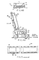
- FIG. 5 illustrates a conventional negative strip 80 of 135 film.
- the strip 80 includes a plurality of frames 82 (as shown, three frames), each of the frames containing an image and being identified by a number 84 and a bar code 86.
- the bar code includes information such as the frame number, film speed, film type, and film length.
- the negative also includes tracking holes 88 for tracking through a camera.
- Negatives can be used to make reprints of an image onto photographic paper.
- negatives are the original source of the image and thus the best source for high quality reprints.
- the process of making a reprint from a negative is labor intensive and fraught with mistakes.
- an operator must align the tracking holes or sides of the negative strip and carefully insert the strip into a feeder. If misaligned, the negative strip will not feed properly and the feeder may jam or otherwise malfunction.
- the strip must be fed with the emulsion side faced upward, so that a camera can form the image on a print.
- the operator After feeding the strip, the operator enters order information such as the quantity and size of reprints for a given frame number. This requires a step of monitoring which frame is in position under the camera while simultaneously reading and inputting the order information from an envelope or other source into the reprint machine.
- U.S. Patent 5,841,885 discloses a digital recordation device which scans a negative strip to produce a digital file of the negative and prints a digital record of the file on the reverse side of a print.
- the above patent does not address the aforementioned deficiencies in the photographic reprint process. It would be desirable to have an improved digital photographic reprint process and apparatus which corrects the feeding problems in the prior art.
- orders for new prints, CDs, Index Prints, and digital files can be made from negatives using a reorder system and method including the steps of reading a bar code from a negative strip corresponding to individual frames on the negative and scanning the images corresponding to the given frames, in order to reproduce an image which is automatically manipulated by computer software so that the image is in a proper orientation to fulfill the order. Accordingly, an operator need not feed the negative strip in a particular orientation, because the image orientation will automatically be corrected after the scanning step.
- a multiple strip feeder is disclosed for feeding a stack of negative strips into the reorder system.
- the digital reorder system of the present invention includes a digital data scanner for reading bar code information printed on a negative strip and a digital camera for scanning images from the strip to form a digital version of the negative image.
- the digital image is stored in an image format file and is automatically manipulated by software residing in one or more computers to ensure it is in the proper orientation.
- information such as frame number, film speed, film type, and film length is automatically inputted into a computer. Such information is automatically matched with order information entered by the operator.
- an operator can feed the negative strips into a strip feeder without engaging in time consuming efforts of positioning each negative so that the emulsion faces upward.
- the operator need only place a stack of negatives in a hopper, and the negatives automatically feed one-by-one into the strip feeder. This frees the operator to insert order information, such as the quantity and size of reprints, into the computer. According to the present invention, operator time is dramatically reduced and processing errors can be avoided.
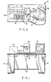
- a photographic reorder station 10 including a digital reprint system and method of the present invention.
- the station is used to process film reorders, including orders for new prints, CDs, Index Prints, and digital files that are produced from digital data gathered by scanning a customer's film.
- an operator at the reorder station 10 typically receives an envelope containing one or more strips of negatives 80 (as shown in FIG. 5) with order information written on the envelope or other source.
- the order information includes the desired quantity and size of reprints marked for one or more frame numbers 84.
- the operator inputs the quantity and size information at the reorder station 10.
- the reorder station includes one or more industrial computers 12 for processing order information entered into a keyboard 14 or other data entry device.
- the keyboard is mounted on an extractable support 15 which adjusts the keyboard to a preferred operator position.
- the station can include a light 16 positioned adjacent a work area 18 on a table where the operator places envelopes and order materials.
- a bar code reader 17 located on or above the table reads dealer and order code information from each envelope. The operator scans the bar code of an envelope and then opens the envelope, removing the negative strips and entering the order information into the computer 12 via the keyboard 14.
- the order information is viewable on a monitor 20, which is preferably an LCD flat panel screen or conventional monitor with a minimum resolution of 800 x 600.
- the reorder station can include a storage cabinet 22 for housing electronics components and power supplies.
- each strip contains one or more images, each image 82 marked with a frame number 84 and a bar code 86 indicative of the frame number and including one or more of the film speed, film type, and film length.
- the operator feeds each strip one-by-one in succession into a strip feeder 24.
- FIG. 3 shows various features of the digital reorder system including the path followed by a negative strip through the system.
- the digital reorder system includes a strip feeder section 26, a film cleaner section 44, a data scanning section 60, and an image scanning section 70.
- the strip feeder section 26 corresponds to the strip feeder 24 shown schematically in FIGS. 1 and 2.
- the negative strip can be inserted into an opening at an input end 30 of the strip feeder section 26 of the digital reorder system and travels along a film track 28 through the system.
- the strip is manually inserted by an operator in accordance with loading line marks (not shown) on the film feeder.
- the strip feeder section includes a plurality of infrared detector sensors 32, 34, 36, and 38 situated parallel to the film track, the sensors detecting the presence of the negative strip in the strip feeder section of the film track 28.
- Associated with each sensor is a film drive roller pair 40, with individual rollers positioned above and below the film track 28.
- the roller pairs 40 are actuated by solenoids 42 in response to film strip detection signals from the sensors.
- the rollers During feeding, the rollers remain disengaged to allow insertion of a negative strip.
- the strip can be inserted in a direction transverse to the path followed by a negative on the film track 28.
- the negative can be inserted from the side (into the page) between at least two consecutive roller sets 40.
- signals are transmitted to the solenoids 42 instructing the rollers to close and thereby engage the strip.
- the negative strip is gripped in the nip of the rollers and conveyed along the film track as driven by a stepper motor 50 which drives the upper roller of its corresponding roller pair 40 and is coupled to the other roller pairs 40 by a conventional belt (not shown).
- the infrared detector sensors positioned along the film track provide signals to the computer 12 to determine the approximate length of the negative strip for use in the image scanning section 70.
- the negative strip is next conveyed to a film cleaner section 44 having infrared detector sensors 46 and 48 positioned adjacent the film track 28 to detect the presence of the negative strip.
- the film cleaner section includes film brush cleaner rollers 54 driven by a film cleaner motor 56 to rotate and clean the surface of the negative strip passing thereby and a vacuum system (not shown) to expunge any dirt or debris from the strip.
- Downstream of the film brush rollers 54 is a second stepper motor 52 for driving the upper roller of its corresponding roller pair 51 to further convey the strip along the film track 28.
- the second stepper motor 52 is coupled to other roller pairs downstream of the second stepper motor 52 to drive the negative strip.
- the stepper motors 50 and 52 are driving their respective rollers at the same speed.
- the solenoids 42 are actuated to cause the roller pairs 40 to disengage, so that another negative strip can be inserted into the strip feeder.
- the solenoids also receive an instruction to disengage roller pairs 40 when the leading edge of the negative strip reaches a sensor 58 in the data scanning section 60 of the reorder system.
- an indicator light (not shown) illuminates, signaling to the operator that another negative strip can be inserted into the strip feeder.
- the data scanning section 60 includes a digital data scanner 62, shown schematically in FIG. 3, which reads the bar code 86 printed beneath each image 82 to obtain the frame number and other information such as the film speed, film type, and film length. Because the data scanner 62 digitally scans the bar code 86, it is able to obtain bar code information from the negative 80 regardless of the orientation of the negative.
- the data scanner is capable of reading the bar code of a negative inserted properly, i.e. with the emulsion side of the negative faced up, or a negative inserted upside-down, where the emulsion side is faced down.
- the data scanner is also capable of reading barcodes on negatives inserted first frame first and last frame first.
- the data scanner 62 provides bar code information to the computer, including the orientation of the bar code and thus the image orientation. It also electronically determines the frame location between images that is used for positioning the film for scanning in the image scanning section 70.
- the stepper motor 52 drives the roller pairs 51, 72, and 74 based on the requirements of the image scanning section, as discussed below.
- the roller pair 72 conveys the negative into the image scanning section 70.
- the negative is conveyed so that a first frame thereof is positioned beneath a digital camera 90 (see also FIG. 1).
- Data provided by infrared detector sensors 58 and 96 assist in positioning the negative strip.
- a film flattener and mask device 76 is lowered over the negative to flatten and fix the negative in place, and the digital camera 90 scans the image and inputs the scanned image into the computer 12.
- An LED light 78 positioned below the film track 28 provides proper illumination during the scanning procedure.
- the digital camera 90 can include camera cooling intake fans 94 to provide ventilation to the camera.
- the digital camera 90 produces an image file for each image from the negative and displays the scanned image on the monitor 20.
- the operator can view the monitor to verify the accuracy of the image.
- the computer 12 is capable of storing an image file for each image in a permanent file for later access.
- the image scanning section contains density sensors (not shown) which detect the presence of image frames on the negative strip.
- the rollers 72 and 74 are driven to automatically position the negative so that the digital camera 90 accurately scans each image.
- the computer 12 determines whether the image is in a proper orientation, i.e. whether it is right-side-up or upside-down. If the image is upside down or crooked, the computer 12 in accordance with preloaded software automatically manipulates and corrects the image positioning and orientation.
- an operator need not waste valuable time at the strip insertion stage in determining which direction the emulsion faces on a negative strip or whether the negative strip is oriented first frame first or last frame first.
- the operator simply inserts the negative strips one-by-one into the strip feeder, as instructed by the indicator light.
- the operator enters order information including size and quantity of reprints into the computer 12 via the keyboard 14.
- the computer 12 matches the order information with the bar code information and the scanned image and forms the reprints accordingly.
- the negative strip is output from the image scanning section into a strip collector 92.
- a multiple strip feeder 100 is attached to the strip feeder 24 (see FIG. 2) at the input end 30 depicted in FIG. 3.
- the multiple strip feeder 100 is shown in detail in FIGS. 4A and 4B.
- the operator inputs a negative strip width into the computer 12 and inserts flat negative strips into a hopper 110.
- the computer 12 adjusts the width of a bottom plate 112 which is attached by a spring 114 to the hopper 110, as shown in FIG. 4B.
- the bottom plate operates as an outboard strip pusher, adjusting automatically with the bias of the spring 114 to square the negatives inserted therein.
- a hinged top guide and roller assembly 116 rests above the bottom plate 112 such that negatives are inserted into an opening 118 between the top guide and the bottom plate.
- the ends of the negative strips abut a stopper 120.
- the strips are guided into a rest position against the stopper by a foam or rubber roller 122.
- An infrared detector sensor (not shown) detects whether a negative strip is present in the hopper 110. If at least one negative strip is present, a solenoid or air actuated pivot arm 124 having at least one vacuum cup 125 mounted on the end thereof rotates toward the negative strip, engages the strip, and by virtue of suction transports the strip toward exit roller pair 126 and 128.
- Exit roller 126 is a drive roller positioned above the path of the negative strip.
- Roller 128 is a solenoid or air actuated roller which rotates to form a nip with drive roller 126 to convey the negative strip toward the input end of the feeder 24.
- the multiple strip feeder of the present invention allows the operator to insert negative strips into the reorder system regardless of their orientation.
- the operator need only gather the strips from an envelope and drop them into the hopper. Accordingly, processing time is reduced, as the operator need not feed the strips individually into a machine or inspect the negatives to ensure that the emulsion side is faced upward.
- the operator is free to enter order information into the keyboard while the feed process occurs.
Landscapes
- Physics & Mathematics (AREA)
- General Physics & Mathematics (AREA)
- Projection-Type Copiers In General (AREA)
Applications Claiming Priority (4)
| Application Number | Priority Date | Filing Date | Title |
|---|---|---|---|
| US267984 | 1981-05-28 | ||
| US876766 | 1997-06-16 | ||
| US26798401P | 2001-02-09 | 2001-02-09 | |
| US09/876,766 US6556276B2 (en) | 2001-02-09 | 2001-06-07 | Photographic reorder system and method |
Publications (2)
| Publication Number | Publication Date |
|---|---|
| EP1231509A2 true EP1231509A2 (de) | 2002-08-14 |
| EP1231509A3 EP1231509A3 (de) | 2003-01-08 |
Family
ID=26952799
Family Applications (1)
| Application Number | Title | Priority Date | Filing Date |
|---|---|---|---|
| EP01117798A Withdrawn EP1231509A3 (de) | 2001-02-09 | 2001-08-02 | Fotografisches Wiederbestellungssystem und Verfahren |
Country Status (4)
| Country | Link |
|---|---|
| US (1) | US6556276B2 (de) |
| EP (1) | EP1231509A3 (de) |
| JP (1) | JP2002287259A (de) |
| DE (1) | DE20114816U1 (de) |
Families Citing this family (18)
| Publication number | Priority date | Publication date | Assignee | Title |
|---|---|---|---|---|
| DE10240748B4 (de) * | 2002-08-29 | 2010-04-01 | Qimonda Ag | Verfahren zur Planarisierung einer Halbleiterprobe |
| US7121466B2 (en) * | 2003-07-07 | 2006-10-17 | Sirona Inc. | Bar encoding scheme for a scrolling display |
| US7661672B2 (en) * | 2006-04-28 | 2010-02-16 | Michael Tenbrock | Film handling system |
| US7988045B2 (en) * | 2007-05-31 | 2011-08-02 | International Business Machines Corporation | Portable device-based shopping checkout |
| US8794524B2 (en) * | 2007-05-31 | 2014-08-05 | Toshiba Global Commerce Solutions Holdings Corporation | Smart scanning system |
| US20090026270A1 (en) * | 2007-07-24 | 2009-01-29 | Connell Ii Jonathan H | Secure checkout system |
| US8544736B2 (en) | 2007-07-24 | 2013-10-01 | International Business Machines Corporation | Item scanning system |
| US8280763B2 (en) * | 2008-02-26 | 2012-10-02 | Connell Ii Jonathan H | Customer rewarding |
| US8746557B2 (en) | 2008-02-26 | 2014-06-10 | Toshiba Global Commerce Solutions Holding Corporation | Secure self-checkout |
| US8061603B2 (en) * | 2008-03-20 | 2011-11-22 | International Business Machines Corporation | Controlling shopper checkout throughput |
| US7889068B2 (en) * | 2008-03-20 | 2011-02-15 | International Business Machines Corporation | Alarm solution for securing shopping checkout |
| US8229158B2 (en) * | 2008-04-29 | 2012-07-24 | International Business Machines Corporation | Method, system, and program product for determining a state of a shopping receptacle |
| US20090272801A1 (en) * | 2008-04-30 | 2009-11-05 | Connell Ii Jonathan H | Deterring checkout fraud |
| US8155575B2 (en) * | 2008-05-16 | 2012-04-10 | Hewlett-Packard Development Company, L.P. | Systems and methods for orienting media for improved scan quality |
| US20100053329A1 (en) * | 2008-08-27 | 2010-03-04 | Flickner Myron D | Exit security |
| US8704821B2 (en) * | 2008-09-18 | 2014-04-22 | International Business Machines Corporation | System and method for managing virtual world environments based upon existing physical environments |
| US9047742B2 (en) * | 2009-05-07 | 2015-06-02 | International Business Machines Corporation | Visual security for point of sale terminals |
| WO2013105926A1 (en) | 2011-03-22 | 2013-07-18 | Aerovironment Inc. | Invertible aircraft |
Family Cites Families (19)
| Publication number | Priority date | Publication date | Assignee | Title |
|---|---|---|---|---|
| DE4031022A1 (de) * | 1990-10-01 | 1992-04-02 | Agfa Gevaert Ag | Verfahren zur herstellung von kopien von streifenfoermigen kopiervorlagen und zugehoerige vorrichtung |
| US5315348A (en) | 1991-12-31 | 1994-05-24 | Ray Hicks | Automated photographic negative card holder |
| US5354994A (en) | 1991-12-31 | 1994-10-11 | Ray Hicks | Method and apparatus for detecting film edges and film optical centers |
| EP0554639A1 (de) * | 1992-02-06 | 1993-08-11 | Gretag Imaging Ag | Verfahren zur Erstellung fotografischer Kopien von fotografischen Kopiervorlagen in einem fotografischen Kopiergerät |
| US5321465A (en) * | 1993-01-22 | 1994-06-14 | Ray Hicks | Film analyzer apparatus |
| EP0628852B1 (de) * | 1993-06-03 | 2003-03-26 | Noritsu Koki Co., Ltd. | Bildabzugsvorrichtung |
| US6243171B1 (en) * | 1994-07-29 | 2001-06-05 | Fuji Photo Film Co., Ltd. | Laboratory system, method of controlling operation thereof, playback apparatus and method, film image management method, image data copying system and method of copying image data |
| EP1168819A3 (de) * | 1994-08-22 | 2002-08-07 | Nikon Corporation | Bildlesevorrichtung und -verfahren |
| US6118556A (en) * | 1995-03-14 | 2000-09-12 | Noritsu Koki Co., Ltd. | Film information communication apparatus, film information printing apparatus, information processing apparatus and index printer |
| DE69629071T2 (de) * | 1995-03-29 | 2004-04-22 | Eastman Kodak Co. | Vorrichtung zum Drucken, Speichern und Wiederauffinden eines aufgezeichneten Bildes |
| US5841516A (en) * | 1995-04-07 | 1998-11-24 | Noritsu Koki Co., Ltd. | Photographic processing apparatus |
| US5835202A (en) * | 1996-01-11 | 1998-11-10 | Eastman Kodak Company | Photofinishing device with interchangeable film decks |
| JP3496740B2 (ja) | 1996-09-10 | 2004-02-16 | ノーリツ鋼機株式会社 | 写真照合システム |
| US5926288A (en) * | 1996-09-16 | 1999-07-20 | Eastman Kodak Company | Image handling system and method using mutually remote processor-scanner stations |
| US6017157A (en) * | 1996-12-24 | 2000-01-25 | Picturevision, Inc. | Method of processing digital images and distributing visual prints produced from the digital images |
| US6040891A (en) * | 1997-05-14 | 2000-03-21 | Konica Corporation | Photographic printing apparatus |
| US6324345B1 (en) * | 1997-12-10 | 2001-11-27 | Fuji Photo Film Co., Ltd. | Photographic film with recorded information, method of acquiring the information recorded on photographic film, image processing method using the acquired information, and print system using the same |
| US6094541A (en) | 1998-03-04 | 2000-07-25 | Eastman Kodak Company | System and method for transferring images on an image content of a first format to a photosensitive film of a second format |
| US6208770B1 (en) * | 1998-09-18 | 2001-03-27 | Eastman Kodak Company | Digital colored corrected prints produced from colored film |
-
2001
- 2001-06-07 US US09/876,766 patent/US6556276B2/en not_active Expired - Fee Related
- 2001-08-02 EP EP01117798A patent/EP1231509A3/de not_active Withdrawn
- 2001-08-02 DE DE20114816U patent/DE20114816U1/de not_active Expired - Lifetime
-
2002
- 2002-02-12 JP JP2002034681A patent/JP2002287259A/ja active Pending
Also Published As
| Publication number | Publication date |
|---|---|
| DE20114816U1 (de) | 2002-02-14 |
| US6556276B2 (en) | 2003-04-29 |
| EP1231509A3 (de) | 2003-01-08 |
| US20020110374A1 (en) | 2002-08-15 |
| JP2002287259A (ja) | 2002-10-03 |
Similar Documents
| Publication | Publication Date | Title |
|---|---|---|
| US6556276B2 (en) | Photographic reorder system and method | |
| US6452663B1 (en) | Image reproduction apparatus with compact, low-waste digital printer | |
| JP3471131B2 (ja) | 書類読取装置 | |
| US5828469A (en) | Document scanner with gravitational registration | |
| US6813047B1 (en) | Digital image processing system for the manufacture of photographic prints | |
| JP2000264445A (ja) | 給紙装置の用紙サイズ検出装置、画像読取装置およびその制御方法 | |
| JP3495464B2 (ja) | マイクロフィルムカメラのマーク写し込み装置 | |
| JP3637471B2 (ja) | 写真焼付装置 | |
| JPH0812136A (ja) | シート体の重送検出方法 | |
| JPH08208073A (ja) | シート体の重送検出方法および装置 | |
| JP2745258B2 (ja) | マイクロフィルムおよびマイクロフィルムカメラ | |
| JPH11160803A (ja) | 感光材料露光装置及びプリンタプロセッサ | |
| JPH0711669B2 (ja) | 写真焼付装置 | |
| JP3183029B2 (ja) | 写真焼付装置 | |
| JPH11282098A (ja) | 写真用コピ―機および走査装置 | |
| US20060067681A1 (en) | Photo film processing system | |
| JPH08248612A (ja) | 写真プリントの生産方法及び生産システム | |
| JP2002277977A (ja) | 画像読取装置及びその装置を用いた写真処理方法 | |
| JP2002365737A (ja) | 画像処理機 | |
| JPH11102031A (ja) | 受注処理装置及びプリント生産システム | |
| JPH1199714A (ja) | 画像記録システム及び画像記録装置 | |
| JPH05197018A (ja) | マイクロフィルムリ−ダ | |
| JPH09319010A (ja) | 写真処理方法及び現像済短尺フィルム取出装置 | |
| JPH1048756A (ja) | 短尺フィルム供給方法 | |
| JPH05341396A (ja) | 印画紙送り方法及び装置 |
Legal Events
| Date | Code | Title | Description |
|---|---|---|---|
| PUAI | Public reference made under article 153(3) epc to a published international application that has entered the european phase |
Free format text: ORIGINAL CODE: 0009012 |
|
| AK | Designated contracting states |
Kind code of ref document: A2 Designated state(s): AT BE CH CY DE DK ES FI FR GB GR IE IT LI LU MC NL PT SE TR |
|
| AX | Request for extension of the european patent |
Free format text: AL;LT;LV;MK;RO;SI |
|
| RAP1 | Party data changed (applicant data changed or rights of an application transferred) |
Owner name: IMIP LLC |
|
| PUAL | Search report despatched |
Free format text: ORIGINAL CODE: 0009013 |
|
| AK | Designated contracting states |
Kind code of ref document: A3 Designated state(s): AT BE CH CY DE DK ES FI FR GB GR IE IT LI LU MC NL PT SE TR |
|
| AX | Request for extension of the european patent |
Free format text: AL;LT;LV;MK;RO;SI |
|
| 17P | Request for examination filed |
Effective date: 20030212 |
|
| AKX | Designation fees paid |
Designated state(s): CH DE FR GB IT LI |
|
| 17Q | First examination report despatched |
Effective date: 20040618 |
|
| STAA | Information on the status of an ep patent application or granted ep patent |
Free format text: STATUS: THE APPLICATION IS DEEMED TO BE WITHDRAWN |
|
| 18D | Application deemed to be withdrawn |
Effective date: 20041029 |