EP1231580A2 - Fernsteuerungssystem, Fernsteuersender, Programm und Speichermedium für das Fernsteuerungssystem - Google Patents
Fernsteuerungssystem, Fernsteuersender, Programm und Speichermedium für das Fernsteuerungssystem Download PDFInfo
- Publication number
- EP1231580A2 EP1231580A2 EP01309874A EP01309874A EP1231580A2 EP 1231580 A2 EP1231580 A2 EP 1231580A2 EP 01309874 A EP01309874 A EP 01309874A EP 01309874 A EP01309874 A EP 01309874A EP 1231580 A2 EP1231580 A2 EP 1231580A2
- Authority
- EP
- European Patent Office
- Prior art keywords
- data
- transmitter
- transmission
- identification information
- timing
- Prior art date
- Legal status (The legal status is an assumption and is not a legal conclusion. Google has not performed a legal analysis and makes no representation as to the accuracy of the status listed.)
- Granted
Links
Images


Classifications
-
- G—PHYSICS
- G09—EDUCATION; CRYPTOGRAPHY; DISPLAY; ADVERTISING; SEALS
- G09B—EDUCATIONAL OR DEMONSTRATION APPLIANCES; APPLIANCES FOR TEACHING, OR COMMUNICATING WITH, THE BLIND, DEAF OR MUTE; MODELS; PLANETARIA; GLOBES; MAPS; DIAGRAMS
- G09B25/00—Models for purposes not provided for in G09B23/00, e.g. full-sized devices for demonstration purposes
- G09B25/04—Models for purposes not provided for in G09B23/00, e.g. full-sized devices for demonstration purposes of buildings
-
- G—PHYSICS
- G08—SIGNALLING
- G08C—TRANSMISSION SYSTEMS FOR MEASURED VALUES, CONTROL OR SIMILAR SIGNALS
- G08C17/00—Arrangements for transmitting signals characterised by the use of a wireless electrical link
Definitions
- the present invention relates to a system for carrying out remote control with respect to driving apparatuses such as automobiles and robots, and in particular, to a remote control system, which is suitable in the case where there is a need of simultaneously controlling a plurality of driving apparatuses at the same place.
- a transmission data from each transmitter is composed of combining a data section equivalent to actual control information, a unit data section comprising a space section having a time length more than a transmission time of the data section, and a wait section having a time length more than the unit data section.
- the combination of the unit data section and the wait section is changed. By doing so, it is possible to produce a state such that the data section transmitted from each transmitter does not overlap with each other.
- the above remote control system does not carry out a control for synchronizing a transmission timing of data from each transmitter, and each transmitter transmits data according to a transmission pattern in response to the self-identification data. For this reason, when the number of transmitters increases, a frequency that the transmission timing of data from each transmitter overlaps with each other increases, while a probability that data is transmitted from only one transmitter decreases. As a result, a problem arises such that each driving apparatus is not smoothly controlled. In particular, in the case where it is required to continue to operate many driving apparatuses, the above confusion arises at a high probability.
- an object of the present invention is to provide a remote control system, which can smoothly carry out remote control with respect to a plurality of driving apparatuses at the same place.
- the present invention provides a remote control system, which independently operates a plurality of driving apparatuses by remote control using a plurality of transmitters prepared so as to correspond to the driving apparatuses, each of the plurality of transmitters comprising: a data transmission device for transmitting data including identification information peculiar to each transmitter for identifying each transmitter and control information for controlling the driving apparatuses; a reception device for receiving data transmitted from other transmitters; a timing setup device for setting a self-data transmission timing based on the identification information included in the received data; and a transmission control device for making the data transmission device transmit the data according to the set timing, each of the plurality of driving apparatuses comprising: a reception device for receiving transmission data from each transmitter; and a control device for comparing the identification information included in the received data with an allocated self-identification information, and making a decision whether or not the received data is a data transmitted to the self, and further, carrying out an operation control based on the data when the data is transmitted to the self.
- each transmitter can receive data transmitted from other transmitters, so that the data transmission timing can be adjusted between transmitters.
- the transmission timing of data from each transmitter is set so as to be mutually shifted, and therefore, it is possible to prevent data interference. By doing so, even in the case where a plurality of transmitters is simultaneously used, it is possible to smoothly operate the driving apparatus corresponding to each transmitter by remote control.
- various mobile elements such as vehicles, robots, and animal type toys and the like are included as the driving apparatuses.
- the present invention is applicable to the case where mutually different portions of single object are operated as mutually different driving apparatuses by remote control using a plurality of transmitters.
- the following transmitter is used; more specifically, the A transmitter, which is transmits a control signal or the like by using various transmission waves such as an infrared ray and a radio wave and the like, can be used as the transmitter of the present invention.
- An identification number is used a An identification number can be used as the identification information allocated to the transmitter and the driving apparatus.
- remote control systemof the present invention may include the following preferred embodiments.
- a period when each transmitter is allowed to transmit a data is predetermined so as not to overlap with each other in a predetermined cycle based on the identification information allocated to each transmitter, the timing setup device specifies, when receiving data transmitted from other transmitters, a time remaining until the self-data transmission timing comes in the cycle based on the identification information included in the receiving data, and the transmission control device makes the data transmission device start the data transmission when the specified time elapses.
- each transmitter can specify the self-data transmission timing when each transmitter should transmit the self data by referring to the data transmission from other transmitter.
- the data transmission of each transmitter is carried out every predetermined cycle; therefore, even if one transmitter interrupts data transmission on the midway, the remaining transmitter can transmit data for the period allocated to the selfat the self-allocated timing.
- the period when each transmitter is allowed to transmit the data in the predetermined cycle may be set to mutually equal time with respect to each transmitter .
- the sequence of data transmission of each transmitter in the predetermined cycle is merely predetermined, and thereby, each transmitter can specify a period when each transmitter is allowed to transmits the datacapable of transmitting the self-data. More specifically, if a time of the transmission period given to each transmitter is set as T, when data transmission is started from the transmitter having the first transmission sequence, the transmitter having the next transmission sequence starts data transmission after time T elapses, and further, the transmitter having the next transmission sequence starts data transmission after time 2T elapses. As described above, transmission start timing of one transmitter is found, and thereby, it is possible to readily specify transmission timing from transmission sequence and time allocated to each transmitter.
- the timing setup device may set transmission timing of the data so that the self data transmission device repeats data transmission in the predetermined cycle in the case where it can not receive data from other transmitters. In this case, even in a state that data transmission from all transmitters excluding the self is stopped, it is possible to repeatedly transmit data from the transmitter itself at correct timing.
- Each transmitter may include a hold device, which makes a decision whether or not the identification information included in the data transmitted from other transmitter is the same as the identification information set to the self, and holds, in the case where a decision is made such that both information are the same, a transmission timing setup by the timing setup device until receiving data including an identification information different from the self-identification information. In this case, it is possible to prevent interference in the case where identification information overlaps with each other between the plurality of transmitters.
- Each transmitter may include a transmission data confirming device, which compares a data transmitted at the timing set by the timing setup device with a data received concurrently with the transmission, and makes the hold device carry out a procedure when both data are not correspondent. In this case, interference is detected as the result that data is simultaneously transmitted from other transmitters, and thereby, it is possible to adjust data transmission timing so that no interference is again generated.
- the present invention provides a transmitter for remote control system, which is prepared for each of driving apparatuses to independently operate the driving apparatuses by remote control, comprising: a data transmission device for transmitting data including identification information peculiar to the transmitter and control information for controlling the driving apparatus; a reception device for receiving data transmitted from other transmitters; a timing setup device for setting a self-data transmission timing based on the identification information included in the received data; and a transmission control device for making the data transmission device transmit the data according to the set timing.
- the transmitter is prepared for each driving apparatus, and then, the same identification information is set to the paired driving apparatus and transmitter so that each driving apparatus is controlled based on the data including the same identification information, and thereby, the remote control system of the present invention is constructed.
- the transmitter of the present invention may include various preferred embodiments in the above remote control system. More specifically, a period when the transmitter is allowed to transmit a data is predetermined in a predetermined cycle based on the identification information, the timing setup device specifies, when receiving data transmitted from other transmitters, a time remaining until the self-data transmission timing comes in the cycle based on the identification information included in the receiving data, and the transmission control device makes the data transmission device start the data transmission when the specified time elapses. Further, the period when the transmitter is allowed to transmit the data in the predetermined cycle may be set to a time equal to time transmitting data with respect to other transmitters.
- the timing setup device may set transmission timing of the data so that the self data transmission device repeats data transmission in the predetermined cycle in the case where it can not receive data from other transmitters.
- the transmitter may further include a hold device, which makes a decision whether or not the identification information included in the data transmitted from other transmitter is the same as the identification information set to the self, and holds, in the case where a decision is made such that both information are the same, a transmission timing setup by the timing setup device until receiving data including an identification information different from the self-identification information.
- the transmitter may further include a transmission data confirming device, which compares a data transmitted at the timing set by the timing setup device with a data received concurrently with the transmission, and makes the hold device carry out a procedure when both data are not correspondent.
- the present invention provides a remote control system program used for a transmitter, which includes a data transmission device for transmitting data including identification information peculiar to the transmitter and control information for controlling the driving apparatus, a reception device for receiving data transmitted from other transmitters, and a computer for controlling data transmission based on the received data, and which is prepared for each of driving apparatuses to independently operate the driving apparatuses by remote control, the program being constructed to allow the computer to serve as: a timing setup device for setting a self-data transmission timing based on the identification information included in the data received by the reception device; and a transmission control device for making the data transmission device transmit the data according to the set timing.
- the computer of the transmitter reads and executes the program, and thereby, the transmitter of the present invention is constructed.
- the program of the present invention may include various preferred embodiments in the above remote control system. More specifically, a period when the transmitter is allowed to transmit a data is predetermined in a predetermined cycle based on the identification information, the timing setup device specifies, when receiving data transmitted from other transmitters, a time remaining until the self-data transmission timing comes in the cycle based on the identification information included in the receiving data, and the transmission control device makes the data transmission device start the data transmission when the specified time elapses. Further, the period when the transmitter is allowed to transmit the data in the predetermined cycle may set to a time equal to time transmitting data with respect to other transmitters.
- the timing setup device may set transmission timing of the data so that the self data transmission device repeats data transmission in the predetermined cycle in the case where it can not receive data from other transmitters.
- the program may being constructed to allow the computer to serve further as a hold device, which makes a decision whether or not the identification information included in the data transmitted from other transmitter is the same as the identification information set to the self, and holds, in the case where a decision is made such that both information are the same, a transmission timing setup by the timing setup device until receiving data including an identification information different from the self-identification information.
- the program may being constructed to allow the computer to serve further as a transmission data confirming device, which compares a data transmitted at the timing set by the timing setup device with a data received concurrently with the transmission, and makes the hold device carry out a procedure when both data are not correspondent.
- program of the present invention may be provideds through a computer readable storage medium.
- FIG. 1 is a view showing a schematic configuration of remote control system according to the present invention.
- FIG. 1 there is shown the case where remote control is carried out with respect to three driving apparatuses 1...1 at the same place.
- a transmitter 2...2 is prepared so as to make one-to-one correspondence to each driving apparatus 1.
- Numbers 1 to 3 are given as identification number (ID) to these driving apparatuses 1...1 and transmitters 2...2.
- the driving apparatus 1 and the transmitter 2 having the same identification number form a pair, and each driving apparatus 1 is operated by remote control based on a data from the transmitter 2 having the same identification number.
- An infrared ray is used in the remote control operation of each driving apparatus 1.
- each transmitter 2 is provided with a remote control signal emitting section (unit) 3; on the other hand, each driving apparatus 1 is provided with a remote control signal receiving section 4. Further, in order to take synchronization of data transmission from each transmitter 2, each transmitter 2 is provided with a remote control signal receiving section 5.
- FIG. 2 is a view showing a circuit configuration of the transmitter 2.
- the transmitter 2 is provided with the above remote control signal emitting and receiving sections 3 and 5. Further, the transmitter 2 is provided with a control circuit 10 for generating a transmission data and controlling other circuits, an input device 11 such as operation key, switch or volume for controlling an operation of the driving apparatus 1, and a switch 12 for setting an identification number.
- the operating state of the input device 11 by an operator is detected by an input circuit 13, and an operation signal in response to the operating state of the input device 11 is inputted from the input circuit 13 to the control circuit 10.
- the identification number set by an identification number setting switch 12 is read by the control circuit 10.
- the identification number set by the identification setting switch 12 may be arbitrarily selected from a range predetermined by an operator or system administrator and the like, ormaybe fixed to a specified number predetermined by a manufacturer of the transmitter 2.
- the remote control signal emitting section 3 includes a light emitting device, for example, such as an LED or the like, and emits an infrared ray in response to an instruction from a transmission circuit 14.
- the transmission circuit 14 outputs a transmission data to the remote control signal emitting section 3 according to a timing instructed from an output timing creating circuit 15.
- the data outputted to the remote control signal emitting section 3 is generated by the control circuit 10, and the transmission circuit 14 modulates the data generated by the control circuit 10 by a remote control signal carrier signal so as to drive the remote control signal emitting section 3.
- the output timing creating circuit 15 counts time according to a timer setup value given from the control circuit 10, and then, outputs a transmission instruction when a time corresponding to the timer setup value elapses.
- a frequency of the infrared carrier signal outputted from the remote control signal emitting section 3 is the same in all transmitters 2.
- the remote control signal receiving section 5 receives an infrared ray transmitted from other transmitters 2, and then, outputs a signal eliminating a carrier component from the received infrared ray to a reception circuit 16.
- the reception circuit 16 decodes the signal given from the remote control signal receiving section 5 into one block remote control data, and thereafter, outputs the data to a received data determining circuit 17.
- the one block remote control data is composed of an identification number and control information on a pair of right and left motors (motor 28; 28 shown in FIG. 4) provided in the driving apparatus 1, as shown in FIG. 3.
- the control information on right and left motors is composed of information (F/R determination) for determining which the rotational direction of each motor is forward or rearward direction and information for specifying a driving speed of motor.
- the bit number of one block remote control data is always constant. Thus, time spent for transmitting one block remote control data is constant.
- the received data determining circuit 17 determines an identification number of received data given from the reception circuit 16, and thereafter, supplies the determination result to the control circuit 10. Then, the control circuit 10 controls the operation of the transmission circuit 14 and the output timing creating circuit 15 based on information given from the received data determining circuit 17, the identification number setup switch 12 and the input circuit 13. Further, the control circuit 10 makes a decision as to whether or not interference is made and sets an output timing when the self-transmission data is to be transmitted, based on the identification number of received data given from the received data determining circuit 17 and the self-identification number set by the identification number setup switch 12. Subsequently, the control circuit 10 sets a timer setup value with respect to the output timing creating circuit 15 in accordance with the set output timing. Further, the control circuit 10 generates a transmission data to the driving apparatus 1 having the same identification number as the self-identification number based on information given from the identification number setup switch 12 and the input circuit 13, and thereafter, outputs the transmission data to the transmission circuit 14.
- control circuit 10 is connected with a power switch and the like; however, these elements are omitted.
- one transmitter 2 may be provided with two or more remote control signal receiving sections 5 having different detection direction.
- the control circuit 10 may be composed of combining a microcomputer and a predetermined program.
- the transmission circuit 14, output timing creating circuit 15, reception circuit 16 and received data determining circuit 17 may be composed as a logical circuit, and may be composed of combining a microcomputer and a predetermined program like the control circuit 10. At least any one of the output timing creating circuit 15 and the received data determining circuit 17 may be integrated with the control circuit 10.
- FIG. 4 is a view showing an automobile model as one embodiment of driving apparatuses 1.
- FIG. 4(a) is a side view of the automobile model
- FIG. 4(b) is a bottom view thereof
- FIG. 4(c) is a rear view thereof.
- the driving apparatus 1 comprises an automobile model 20.
- the automobile model 20 has a chassis 21, and a body 22 covering the upper portion of the chassis.
- the chassis 21 is provided with a front wheel 23 on the center at its front portion, and is provided with a pair of right and left rear wheels 24 and 24 at its rear portion.
- the front wheel 23 is rotatably attached to a support beam 25 via an axle 25a.
- the support beam 25 is mounted so as to be rotatable around a turning shaft 26 vertical to the chassis 21.
- the front wheel 23 is freely rotatable around the turning shaft 26 in a range of 360°.
- the chassis 21 is attached with dummy wheels 27 and 27 on the right and left sides of the front portion.
- these dummy wheels 27 are floating, and thus, the chassis 21 is supported by the front wheel 23 and the rear wheels 24 and 24.
- the rear portion of the chassis 21 is provided with motors 28 and 28, which are vertically overlappedwith each other.
- Each motor 28 is provided in order to drive the rear wheel 28 independently.
- An output shaft 28a of each motor 28 is attached with a pinion 29, and the rotation of the pinion 29 is transmitted via a gear train 30 to the rear wheel 24, which is a driving object.
- right and left rear wheels 24 and 24 are independently driven by each motor 28. Therefore, a rotational speed of the motors 28 and 28 is changed in right and left motor, and only one motor 28 is driven, or the motors 28 and 28 are rotated to a direction different from each other, and by doing so, various turning motions can be given to the automobile model 20.
- a control unit 32 comprising, for example, a one-chip microcomputer is provided above the battery 31.
- the rear portion of the chassis 21 is provided with an LED 33 for making a decision whether or not power is turned on.
- the upper central portion of the body 22 is provided with a remote control signal receiving section 34 for receiving an infrared ray from the transmitter 2.
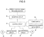
- FIG. 5 shows a circuit configuration of control system mounted into the automobile model 20.
- the automobile model 20 is provided with the aforesaid remote control signal receiving section 34.
- the remote control signal receiving section 34 receives an infrared ray transmitted from the transmitter 2, and then, outputs a signal eliminating a carrier component from the received infrared ray to a reception circuit 35.
- the reception circuit 35 decodes a signal given from the remote control signal receiving section 34 into one block remote control data, and then, outputs the data to a control circuit 37.
- the one block remote control data is as shown in FIG. 3.
- the control circuit 37 determines an identification number of received data given from the reception circuit 35, and then, compares the identification number with the identification number set by a identification number setup switch 38, and thereafter, makes a decision whether the remote control data is valid or invalid. More specifically, if the identification number is not correspondent, the control circuit 37 makes a decision that the received remote control data is invalid, and thus, generates no driving signal of the motor 28. On the other hand, if the identification number is correspondent, the control circuit 37 determines a rotating direction and a rotational speed of the motor 28 based on motor control information of the remote control data given from the reception circuit 35. Thereafter, the control circuit 37 outputs a motor driving signal in response to the determined value to motor driving circuits 39 and 39.
- Each motor driving circuit 39 controls a rotation of the motor 28 based on the given motor driving signal.
- the identification number setup switch 38 may be designed such that an operator, a system manager or the like can select any number from a predetermined range, or a manufacturer of the transmitter 2 may previously fix the identification number at a specific number.
- the control circuit 37 is connected with a power switch 40. The battery 31 and the LED 33 shown in FIG. 4 are omitted in FIG. 5.
- each transmitter 2 specifies self-transmission timing while receiving a remote control signal transmitted from other transmitters. By doing so, the transmission timing is synchronized so that the transmission timing of each transmitter 2 does not overlap with each other. The following is a description on this point.
- FIG. 6 is a view showing the way to take transmission timing in the case where four transmitters 2 are simultaneously used.
- the transmission timing of each transmitter 2 is shifted by T in succession from the identification number 1.
- each transmitter 2 controls the transmission timing, and thereby, it is possible to prevent the transmission timings from four transmitters 2 from overlapping with each other.
- the transmission timing may be controlled in the following manner.
- the transmitter 2 having the identification number 2 receives a data having identification number 1, subsequently, the transmitter 2 starts a self-transmission data output, and then, completes the self-transmission data output at the time t2.
- the transmitter 2 having the identification number 2 checks the received data of the reception circuit 16 (see fig. 2), and thereafter, confirms that no signal interference is generated. Thereafter, the transmitter 2 having the identification number 2 sets the transmission timer counting the next output timing at 3T, and then, starts timer count.
- the transmitter 2 having the identification number 2 resets the transmission timer at 2T, and then, starts timer count.
- the transmitter 2 having the identification number 2 resets the transmission timer at T, and then, starts timer count.
- the transmitter 2 having the identification number 2 starts an output of self-data at the point of time when the transmission timer count advances by time T after receiving the data of the identification number 4. Further, in the case where the transmitter 2 having the identification number 2 can not receive the data from other transmitters 2, it can continuously output the transmission data at a period 4T by using the time 3T set in the transmission timer when the self-data transmission is completed.
- the above embodiment has described the case where the transmitter 2 is four. By adding the identification number, it is possible to control the transmission timing in the case where the transmitter 2 is five or more, likewise.
- the period of transmission timing of each transmitter 2 is N ⁇ T (N is number of transmitters). In this case, a blank time transmitting no data from any transmitters may be taken between times when each transmitter 2 transmits data, and thereby, the whole period may be set longer than the period NT.
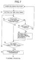
- FIG. 7 is a flowchart showing a procedure of power-on operation executed by the control circuit 10 of transmitter 2 until self-data transmission start from power-on.
- the control circuit 10 sets a time over timer (step S1).
- the control circuit 10 makes a decision whether or not the data from other transmitters 2 is received (step S2). If the data is received, the control circuit makes a decision whether or not the identification number of the received data is the same as the identification number set with respect to the self-transmitter 2 (step S3). If the identification number is correspondent, the control circuit 10 returns to step S1, and then, repeats the determining operation. By doing so, it is possible to prevent interference in the case where there exists a plurality of transmitters 2 having the same identification number.
- control circuit 10 makes a decision that the identification number is not correspondent in step S3
- the control circuit 10 sets a self-output timing in accordance with the identification number of other transmitters 2 (step S4). For example, if the transmitter 2 having the identification number 2 receives the data of the identification number 3, it sets the self-output timing at 2T.
- step S5 the control circuit 10 makes a decision whether or not the timer set in step S1 is time over (step S5), and if it is not time over, the control sequence returns to step S2. If the timer is time over, the control circuit starts the self-data transmission (step S6). In this case, the output is actually started at the point of time when the output timing set in step S4 comes. In the case where the data is not received until time over, the transmitter is solely operated; namely, no other transmitters exist, and therefore, data transmission is started at once in step S6.
- the control circuit 10 controls a data transmission according to the procedure of a normal operation shown in FIG. 8.
- the control circuit 10 makes a decision whether or not data from other transmitters 2 is received (step S11). If the data is received, the control circuit 10 makes a decision whether or not the identification number of the received data is the same as the identification number set with respect to the self-transmitter 2 (step S12). If the identification number is correspondent, the control sequence returns to the power-on operation shown in FIG. 7. On the other hand, if the identification number of the received data is different from the self-identification number, the control circuit 10 sets the self-output timing to the transmission timer in accordance with the identification number of the received data (step S13). Next, the control circuit makes a decision whether or not the transmission timer reaches time up (step S14), and then, returns to step S1 until the time up comes.
- step S15 When a decision is made such that the time up comes in step S4, the control circuit 10 starts the self-data transmission (step S15). At that time, the control circuit 10 concurrently receives data. Next, the control circuit 10 makes a decision whether or not the data transmission is completed (step S16). If the data transmission is completed, the control circuit 10 compares the transmitted data with data received concurrently with the transmission (step S17). If the data is not correspondent, a decision is made such that interference is generated, and then, the control sequence proceeds to the power-on operation of FIG. 7. If the data is correspondent, no interference is regarded as being generated, and then, the control circuit 10 set the next output timing to the transmission timer (step S18). Thereafter, the control sequence returns to step S1.
- the present invention is not limited to the above embodiment, and various modifications may be made.
- the driving apparatus is not limited to automobile models, and various mobile models may be used.
- the transmitter maybe an operator portable type, or may be installed.
- a specific program is installed in portable (mobile) apparatuses such as a portable game machine and a mobile phone, and then, these apparatuses may be used as a transmitter.
- each transmitter can receive data transmitted from other transmitters, so that the data transmission timing can be set so as not to overlap with each other between transmitters; as a result, it is possible to prevent data interference.
- the transmitter and program of the present invention it is possible to readily realize the remote control system of the present invention.
Landscapes
- Engineering & Computer Science (AREA)
- Physics & Mathematics (AREA)
- General Physics & Mathematics (AREA)
- Computer Networks & Wireless Communication (AREA)
- Educational Technology (AREA)
- Educational Administration (AREA)
- Business, Economics & Management (AREA)
- Theoretical Computer Science (AREA)
- Selective Calling Equipment (AREA)
- Toys (AREA)
- Small-Scale Networks (AREA)
- Mobile Radio Communication Systems (AREA)
- Transmitters (AREA)
Applications Claiming Priority (2)
| Application Number | Priority Date | Filing Date | Title |
|---|---|---|---|
| JP2001034042 | 2001-02-09 | ||
| JP2001034042A JP3451073B2 (ja) | 2001-02-09 | 2001-02-09 | 遠隔操作システム、それに使用する送信機、遠隔操作システム用のプログラム及び記憶媒体 |
Publications (3)
| Publication Number | Publication Date |
|---|---|
| EP1231580A2 true EP1231580A2 (de) | 2002-08-14 |
| EP1231580A3 EP1231580A3 (de) | 2003-03-26 |
| EP1231580B1 EP1231580B1 (de) | 2005-05-11 |
Family
ID=18897711
Family Applications (1)
| Application Number | Title | Priority Date | Filing Date |
|---|---|---|---|
| EP01309874A Expired - Lifetime EP1231580B1 (de) | 2001-02-09 | 2001-11-23 | Fernsteuerungssystem und Fernsteuersender dafür |
Country Status (7)
| Country | Link |
|---|---|
| US (1) | US6819259B2 (de) |
| EP (1) | EP1231580B1 (de) |
| JP (1) | JP3451073B2 (de) |
| KR (2) | KR100446896B1 (de) |
| CN (1) | CN1243413C (de) |
| AT (1) | ATE295596T1 (de) |
| DE (1) | DE60110740T2 (de) |
Cited By (2)
| Publication number | Priority date | Publication date | Assignee | Title |
|---|---|---|---|---|
| JPWO2005009572A1 (ja) * | 2003-07-29 | 2006-09-07 | 株式会社コナミデジタルエンタテインメント | 模型用走行装置、並びにその走行装置を備えた模型及び遠隔操作玩具 |
| EP2923910B1 (de) * | 2013-12-13 | 2019-03-06 | MAN Truck & Bus AG | Vorrichtung und verfahren zur verarbeitung einer drehmomentanforderung für eine antriebsmaschine und zur reduzierung von triebstrangschlägen |
Families Citing this family (20)
| Publication number | Priority date | Publication date | Assignee | Title |
|---|---|---|---|---|
| JP3451073B2 (ja) | 2001-02-09 | 2003-09-29 | コナミ株式会社 | 遠隔操作システム、それに使用する送信機、遠隔操作システム用のプログラム及び記憶媒体 |
| JP3788590B2 (ja) * | 2001-09-28 | 2006-06-21 | コナミ株式会社 | 遠隔操作システム及びその駆動機器 |
| JP3709393B2 (ja) | 2001-12-14 | 2005-10-26 | 富士ソフトエービーシ株式会社 | 遠隔制御システム及び遠隔制御方法 |
| US20030142796A1 (en) * | 2002-01-25 | 2003-07-31 | Ames Stanley R. | Tone adapter for the control of model railroads |
| JP2004140499A (ja) * | 2002-10-16 | 2004-05-13 | Tomy Co Ltd | リモコン玩具 |
| JP4424922B2 (ja) * | 2003-04-02 | 2010-03-03 | 株式会社コナミデジタルエンタテインメント | 遠隔操作玩具、それに用いる無線機及び駆動機器、並びに遠隔操作玩具における識別コード設定方法 |
| JP3907609B2 (ja) * | 2003-04-30 | 2007-04-18 | 株式会社ソニー・コンピュータエンタテインメント | ゲーム実行方法、ゲーム機、通信方法および通信装置 |
| US20050075764A1 (en) * | 2003-09-22 | 2005-04-07 | Canac Inc. | Remote control system for a locomotive having user authentication capabilities |
| JP2005115654A (ja) * | 2003-10-08 | 2005-04-28 | Sony Corp | 情報処理装置および方法、プログラム格納媒体、並びにプログラム |
| US7589642B1 (en) * | 2003-12-16 | 2009-09-15 | Uei Cayman Inc. | Relaying key code signals through a remote control device |
| US8040837B2 (en) * | 2005-06-10 | 2011-10-18 | Panasonic Corporation | Wireless communication apparatus and wireless communication method |
| US8064370B2 (en) * | 2006-03-02 | 2011-11-22 | Panasonic Corporation | Transmitting device, wireless communication system and transmitting method |
| JP4770635B2 (ja) * | 2006-08-09 | 2011-09-14 | 株式会社デンソー | 車車間通信システム、車車間通信方法 |
| WO2008083577A1 (fr) * | 2006-12-29 | 2008-07-17 | Zhongshan Techboy Electron Technology Cd., Ltd | Jouet à commande électrique, et procédé de codage et d'adaptation de codage du jouet |
| CN100525873C (zh) * | 2007-10-19 | 2009-08-12 | 中山市泰宝电子科技有限公司 | 一种电控玩具的编码对码方法及其电控玩具 |
| US8130079B2 (en) | 2007-08-15 | 2012-03-06 | At&T Intellectual Property I, L.P. | Methods, systems, and products for discovering electronic devices |
| JP4618279B2 (ja) * | 2007-08-16 | 2011-01-26 | ソニー株式会社 | リモートコントロールシステム、受信装置および電子機器 |
| CN100583177C (zh) * | 2007-10-19 | 2010-01-20 | 中山市泰宝电子科技有限公司 | 一种电控玩具的浮动编码方法 |
| KR101456165B1 (ko) * | 2014-03-06 | 2014-11-04 | 주식회사 엘로코 | 전계 발광 장치 및 이의 제어 방법 |
| JP6237905B2 (ja) * | 2015-01-15 | 2017-11-29 | 株式会社ベイビッグ | 無線通信システム及び無線通信方法 |
Family Cites Families (9)
| Publication number | Priority date | Publication date | Assignee | Title |
|---|---|---|---|---|
| DE2362765A1 (de) | 1973-12-17 | 1975-06-19 | Battelle Institut E V | Verfahren zur funkfernsteuerung einer groesseren anzahl voneinander unabhaengiger geraete ueber einen gemeinsamen hochfrequenz-kanal |
| DE2449660C3 (de) | 1974-10-18 | 1982-12-16 | Theimeg-Elektronikgeräte GmbH & Co, 4060 Viersen | Verfahren und Einrichtung zur Synchronisation von im Zeitmultiplex arbeitenden, untereinander gleichberechtigten autonomen Geberstationen |
| DE2639363C2 (de) | 1976-09-01 | 1984-05-30 | Steuerungstechnik GmbH, 8000 München | Anordnung zum drahtlosen Steuern mehrerer voneinander unabhängiger Objekte |
| JPH03273797A (ja) * | 1990-03-22 | 1991-12-04 | Nec Corp | リモートコントロールシステム |
| JPH07112302B2 (ja) * | 1992-09-14 | 1995-11-29 | エスエムケイ株式会社 | リモ−トコントロ−ルシステムの送受信方式 |
| JPH1013968A (ja) * | 1996-06-25 | 1998-01-16 | Toshiba Corp | リモートコントロール装置 |
| JP3268271B2 (ja) * | 1998-08-05 | 2002-03-25 | 株式会社シー・シー・ピー | 無線操縦システム |
| US6346047B1 (en) * | 1999-01-08 | 2002-02-12 | Eleven Engineering Inc | Radio frequency remote game controller |
| JP3451073B2 (ja) | 2001-02-09 | 2003-09-29 | コナミ株式会社 | 遠隔操作システム、それに使用する送信機、遠隔操作システム用のプログラム及び記憶媒体 |
-
2001
- 2001-02-09 JP JP2001034042A patent/JP3451073B2/ja not_active Expired - Lifetime
- 2001-09-20 CN CNB011418400A patent/CN1243413C/zh not_active Expired - Fee Related
- 2001-09-27 KR KR10-2001-0059893A patent/KR100446896B1/ko not_active Expired - Fee Related
- 2001-11-20 US US09/989,290 patent/US6819259B2/en not_active Expired - Fee Related
- 2001-11-23 AT AT01309874T patent/ATE295596T1/de not_active IP Right Cessation
- 2001-11-23 DE DE60110740T patent/DE60110740T2/de not_active Expired - Lifetime
- 2001-11-23 EP EP01309874A patent/EP1231580B1/de not_active Expired - Lifetime
-
2004
- 2004-03-12 KR KR1020040016817A patent/KR100740750B1/ko not_active Expired - Fee Related
Cited By (5)
| Publication number | Priority date | Publication date | Assignee | Title |
|---|---|---|---|---|
| JPWO2005009572A1 (ja) * | 2003-07-29 | 2006-09-07 | 株式会社コナミデジタルエンタテインメント | 模型用走行装置、並びにその走行装置を備えた模型及び遠隔操作玩具 |
| EP1712262A4 (de) * | 2003-07-29 | 2007-08-15 | Konami Corp | Modelllaufvorrichtung, modell mit einer derartigen laufvorrichtung und ferngesteuertes spielzeug |
| US7479055B2 (en) | 2003-07-29 | 2009-01-20 | Konami Corporation | Running device for model, and model and remote control toy having the running device |
| JP4503533B2 (ja) * | 2003-07-29 | 2010-07-14 | 株式会社コナミデジタルエンタテインメント | 模型用走行装置、並びにその走行装置を備えた模型及び遠隔操作玩具 |
| EP2923910B1 (de) * | 2013-12-13 | 2019-03-06 | MAN Truck & Bus AG | Vorrichtung und verfahren zur verarbeitung einer drehmomentanforderung für eine antriebsmaschine und zur reduzierung von triebstrangschlägen |
Also Published As
| Publication number | Publication date |
|---|---|
| KR20040027844A (ko) | 2004-04-01 |
| DE60110740T2 (de) | 2005-10-06 |
| US6819259B2 (en) | 2004-11-16 |
| KR100740750B1 (ko) | 2007-07-19 |
| CN1368445A (zh) | 2002-09-11 |
| CN1243413C (zh) | 2006-02-22 |
| ATE295596T1 (de) | 2005-05-15 |
| DE60110740D1 (de) | 2005-06-16 |
| US20020109606A1 (en) | 2002-08-15 |
| EP1231580B1 (de) | 2005-05-11 |
| JP2002238083A (ja) | 2002-08-23 |
| KR100446896B1 (ko) | 2004-09-04 |
| KR20020066365A (ko) | 2002-08-16 |
| HK1045901A1 (en) | 2002-12-13 |
| JP3451073B2 (ja) | 2003-09-29 |
| EP1231580A3 (de) | 2003-03-26 |
Similar Documents
| Publication | Publication Date | Title |
|---|---|---|
| US6819259B2 (en) | Remote control system and timing method for operation thereof | |
| JP5021177B2 (ja) | ホストに対する無線ゲームコントローラのバインド | |
| JP2000051541A (ja) | 無線操縦システム | |
| EP1278171B1 (de) | Fernsteuerungssystem und Sender und Antrieb dafür | |
| JPH06205010A (ja) | ワイヤレス通信装置およびこの装置を用いたゲーム機 | |
| US4716576A (en) | Apparatus for controlling transmitter-receiver | |
| EP1685885B1 (de) | Fernbedienungssystem sowie Transmitter und Peripherie-Einheit zum Benutzen des Systems | |
| JP4312418B2 (ja) | 遠隔操作システム、それに使用する送信機、遠隔操作システム用のプログラム及び記憶媒体 | |
| KR100874075B1 (ko) | 원격 조작 시스템에 사용하는 송신기 | |
| HK1045901B (en) | Remote control system and transmitter to be used for the same | |
| JP3788590B2 (ja) | 遠隔操作システム及びその駆動機器 | |
| US7803032B2 (en) | Remote-control toy and extension unit | |
| AU2002337503A1 (en) | Remote control system and moving machine thereof | |
| JP4308626B2 (ja) | 遠隔制御用送信機 | |
| JP2019087927A (ja) | 赤外線操作システム | |
| JP2003338853A (ja) | 識別データ新規作成等の手段を備えた送受信システム | |
| JPH05200160A (ja) | ワイヤレスコントロール装置 | |
| HK1087962A (en) | Remote control system, transmitter and peripheral unit for the use of the system | |
| HK1077033B (en) | Remote oepration toy, radio device and drive used for the same | |
| HK1053803B (en) | Remote control system, transmitter and peripheral unit for the use of the system |
Legal Events
| Date | Code | Title | Description |
|---|---|---|---|
| PUAI | Public reference made under article 153(3) epc to a published international application that has entered the european phase |
Free format text: ORIGINAL CODE: 0009012 |
|
| AK | Designated contracting states |
Kind code of ref document: A2 Designated state(s): AT BE CH CY DE DK ES FI FR GB GR IE IT LI LU MC NL PT SE TR |
|
| AX | Request for extension of the european patent |
Free format text: AL;LT;LV;MK;RO;SI |
|
| RAP1 | Party data changed (applicant data changed or rights of an application transferred) |
Owner name: KONAMI CORPORATION |
|
| PUAL | Search report despatched |
Free format text: ORIGINAL CODE: 0009013 |
|
| AK | Designated contracting states |
Kind code of ref document: A3 Designated state(s): AT BE CH CY DE DK ES FI FR GB GR IE IT LI LU MC NL PT SE TR |
|
| AX | Request for extension of the european patent |
Extension state: AL LT LV MK RO SI |
|
| RIC1 | Information provided on ipc code assigned before grant |
Ipc: 7G 08C 19/28 B Ipc: 7G 08C 23/04 A Ipc: 7A 63H 30/04 B |
|
| 17P | Request for examination filed |
Effective date: 20030909 |
|
| AKX | Designation fees paid |
Designated state(s): AT BE CH CY DE DK ES FI FR GB GR IE IT LI LU MC NL PT SE TR |
|
| 17Q | First examination report despatched |
Effective date: 20031111 |
|
| RTI1 | Title (correction) |
Free format text: REMOTE CONTROL SYSTEM AND TRANSMITTER TO BE USED FOR THE SAME |
|
| GRAP | Despatch of communication of intention to grant a patent |
Free format text: ORIGINAL CODE: EPIDOSNIGR1 |
|
| GRAS | Grant fee paid |
Free format text: ORIGINAL CODE: EPIDOSNIGR3 |
|
| GRAA | (expected) grant |
Free format text: ORIGINAL CODE: 0009210 |
|
| AK | Designated contracting states |
Kind code of ref document: B1 Designated state(s): AT BE CH CY DE DK ES FI FR GB GR IE IT LI LU MC NL PT SE TR |
|
| PG25 | Lapsed in a contracting state [announced via postgrant information from national office to epo] |
Ref country code: IT Free format text: LAPSE BECAUSE OF FAILURE TO SUBMIT A TRANSLATION OF THE DESCRIPTION OR TO PAY THE FEE WITHIN THE PRESCRIBED TIME-LIMIT;WARNING: LAPSES OF ITALIAN PATENTS WITH EFFECTIVE DATE BEFORE 2007 MAY HAVE OCCURRED AT ANY TIME BEFORE 2007. THE CORRECT EFFECTIVE DATE MAY BE DIFFERENT FROM THE ONE RECORDED. Effective date: 20050511 Ref country code: CH Free format text: LAPSE BECAUSE OF FAILURE TO SUBMIT A TRANSLATION OF THE DESCRIPTION OR TO PAY THE FEE WITHIN THE PRESCRIBED TIME-LIMIT Effective date: 20050511 Ref country code: TR Free format text: LAPSE BECAUSE OF FAILURE TO SUBMIT A TRANSLATION OF THE DESCRIPTION OR TO PAY THE FEE WITHIN THE PRESCRIBED TIME-LIMIT Effective date: 20050511 Ref country code: LI Free format text: LAPSE BECAUSE OF FAILURE TO SUBMIT A TRANSLATION OF THE DESCRIPTION OR TO PAY THE FEE WITHIN THE PRESCRIBED TIME-LIMIT Effective date: 20050511 Ref country code: FI Free format text: LAPSE BECAUSE OF FAILURE TO SUBMIT A TRANSLATION OF THE DESCRIPTION OR TO PAY THE FEE WITHIN THE PRESCRIBED TIME-LIMIT Effective date: 20050511 Ref country code: NL Free format text: LAPSE BECAUSE OF FAILURE TO SUBMIT A TRANSLATION OF THE DESCRIPTION OR TO PAY THE FEE WITHIN THE PRESCRIBED TIME-LIMIT Effective date: 20050511 Ref country code: AT Free format text: LAPSE BECAUSE OF FAILURE TO SUBMIT A TRANSLATION OF THE DESCRIPTION OR TO PAY THE FEE WITHIN THE PRESCRIBED TIME-LIMIT Effective date: 20050511 Ref country code: BE Free format text: LAPSE BECAUSE OF FAILURE TO SUBMIT A TRANSLATION OF THE DESCRIPTION OR TO PAY THE FEE WITHIN THE PRESCRIBED TIME-LIMIT Effective date: 20050511 |
|
| REG | Reference to a national code |
Ref country code: GB Ref legal event code: FG4D |
|
| REG | Reference to a national code |
Ref country code: CH Ref legal event code: EP |
|
| REG | Reference to a national code |
Ref country code: IE Ref legal event code: FG4D |
|
| REF | Corresponds to: |
Ref document number: 60110740 Country of ref document: DE Date of ref document: 20050616 Kind code of ref document: P |
|
| PG25 | Lapsed in a contracting state [announced via postgrant information from national office to epo] |
Ref country code: SE Free format text: LAPSE BECAUSE OF FAILURE TO SUBMIT A TRANSLATION OF THE DESCRIPTION OR TO PAY THE FEE WITHIN THE PRESCRIBED TIME-LIMIT Effective date: 20050811 Ref country code: DK Free format text: LAPSE BECAUSE OF FAILURE TO SUBMIT A TRANSLATION OF THE DESCRIPTION OR TO PAY THE FEE WITHIN THE PRESCRIBED TIME-LIMIT Effective date: 20050811 Ref country code: GR Free format text: LAPSE BECAUSE OF FAILURE TO SUBMIT A TRANSLATION OF THE DESCRIPTION OR TO PAY THE FEE WITHIN THE PRESCRIBED TIME-LIMIT Effective date: 20050811 |
|
| PG25 | Lapsed in a contracting state [announced via postgrant information from national office to epo] |
Ref country code: ES Free format text: LAPSE BECAUSE OF FAILURE TO SUBMIT A TRANSLATION OF THE DESCRIPTION OR TO PAY THE FEE WITHIN THE PRESCRIBED TIME-LIMIT Effective date: 20050822 |
|
| REG | Reference to a national code |
Ref country code: HK Ref legal event code: GR Ref document number: 1045901 Country of ref document: HK |
|
| PG25 | Lapsed in a contracting state [announced via postgrant information from national office to epo] |
Ref country code: PT Free format text: LAPSE BECAUSE OF FAILURE TO SUBMIT A TRANSLATION OF THE DESCRIPTION OR TO PAY THE FEE WITHIN THE PRESCRIBED TIME-LIMIT Effective date: 20051019 |
|
| NLV1 | Nl: lapsed or annulled due to failure to fulfill the requirements of art. 29p and 29m of the patents act | ||
| REG | Reference to a national code |
Ref country code: CH Ref legal event code: PL |
|
| PG25 | Lapsed in a contracting state [announced via postgrant information from national office to epo] |
Ref country code: CY Free format text: LAPSE BECAUSE OF FAILURE TO SUBMIT A TRANSLATION OF THE DESCRIPTION OR TO PAY THE FEE WITHIN THE PRESCRIBED TIME-LIMIT Effective date: 20051123 Ref country code: IE Free format text: LAPSE BECAUSE OF NON-PAYMENT OF DUE FEES Effective date: 20051123 |
|
| PG25 | Lapsed in a contracting state [announced via postgrant information from national office to epo] |
Ref country code: LU Free format text: LAPSE BECAUSE OF NON-PAYMENT OF DUE FEES Effective date: 20051130 Ref country code: MC Free format text: LAPSE BECAUSE OF NON-PAYMENT OF DUE FEES Effective date: 20051130 |
|
| ET | Fr: translation filed | ||
| PLBE | No opposition filed within time limit |
Free format text: ORIGINAL CODE: 0009261 |
|
| STAA | Information on the status of an ep patent application or granted ep patent |
Free format text: STATUS: NO OPPOSITION FILED WITHIN TIME LIMIT |
|
| 26N | No opposition filed |
Effective date: 20060214 |
|
| REG | Reference to a national code |
Ref country code: IE Ref legal event code: MM4A |
|
| REG | Reference to a national code |
Ref country code: GB Ref legal event code: 732E |
|
| REG | Reference to a national code |
Ref country code: FR Ref legal event code: TP |
|
| PGFP | Annual fee paid to national office [announced via postgrant information from national office to epo] |
Ref country code: DE Payment date: 20121121 Year of fee payment: 12 Ref country code: FR Payment date: 20121130 Year of fee payment: 12 |
|
| PGFP | Annual fee paid to national office [announced via postgrant information from national office to epo] |
Ref country code: GB Payment date: 20121120 Year of fee payment: 12 |
|
| GBPC | Gb: european patent ceased through non-payment of renewal fee |
Effective date: 20131123 |
|
| REG | Reference to a national code |
Ref country code: FR Ref legal event code: ST Effective date: 20140731 |
|
| REG | Reference to a national code |
Ref country code: DE Ref legal event code: R119 Ref document number: 60110740 Country of ref document: DE Effective date: 20140603 |
|
| PG25 | Lapsed in a contracting state [announced via postgrant information from national office to epo] |
Ref country code: DE Free format text: LAPSE BECAUSE OF NON-PAYMENT OF DUE FEES Effective date: 20140603 |
|
| PG25 | Lapsed in a contracting state [announced via postgrant information from national office to epo] |
Ref country code: GB Free format text: LAPSE BECAUSE OF NON-PAYMENT OF DUE FEES Effective date: 20131123 Ref country code: FR Free format text: LAPSE BECAUSE OF NON-PAYMENT OF DUE FEES Effective date: 20131202 |