EP1231624B1 - Tube à rayons cathodiques comprenant un amortisseur de vibrations pour un masque sous tension - Google Patents
Tube à rayons cathodiques comprenant un amortisseur de vibrations pour un masque sous tension Download PDFInfo
- Publication number
- EP1231624B1 EP1231624B1 EP02290139A EP02290139A EP1231624B1 EP 1231624 B1 EP1231624 B1 EP 1231624B1 EP 02290139 A EP02290139 A EP 02290139A EP 02290139 A EP02290139 A EP 02290139A EP 1231624 B1 EP1231624 B1 EP 1231624B1
- Authority
- EP
- European Patent Office
- Prior art keywords
- border
- mask
- arm
- tension mask
- moveable contact
- Prior art date
- Legal status (The legal status is an assumption and is not a legal conclusion. Google has not performed a legal analysis and makes no representation as to the accuracy of the status listed.)
- Expired - Lifetime
Links
Images


Classifications
-
- H—ELECTRICITY
- H01—ELECTRIC ELEMENTS
- H01J—ELECTRIC DISCHARGE TUBES OR DISCHARGE LAMPS
- H01J29/00—Details of cathode-ray tubes or of electron-beam tubes of the types covered by group H01J31/00
- H01J29/02—Electrodes; Screens; Mounting, supporting, spacing or insulating thereof
-
- H—ELECTRICITY
- H01—ELECTRIC ELEMENTS
- H01J—ELECTRIC DISCHARGE TUBES OR DISCHARGE LAMPS
- H01J29/00—Details of cathode-ray tubes or of electron-beam tubes of the types covered by group H01J31/00
- H01J29/02—Electrodes; Screens; Mounting, supporting, spacing or insulating thereof
- H01J29/06—Screens for shielding; Masks interposed in the electron stream
- H01J29/07—Shadow masks for colour television tubes
-
- H—ELECTRICITY
- H01—ELECTRIC ELEMENTS
- H01J—ELECTRIC DISCHARGE TUBES OR DISCHARGE LAMPS
- H01J2229/00—Details of cathode ray tubes or electron beam tubes
- H01J2229/07—Shadow masks
- H01J2229/0727—Aperture plate
- H01J2229/0738—Mitigating undesirable mechanical effects
- H01J2229/0744—Vibrations
Definitions
- This invention generally relates to cathode ray tubes (CRTs) and, more particularly, to a split foot damper for reducing vibrational energy in a tension mask of a cathode ray tube (CRT).
- a color picture tube includes an electron gun for forming and directing three electron beams to a screen of the tube.
- the screen is located on the inner surface of the faceplate of the tube and comprises an array of elements of three different color-emitting phosphors.
- An aperture mask is interposed between the gun and the screen to permit each electron beam to strike only the phosphor elements associated with that beam.
- the aperture mask is a thin sheet of metal, such as alloy steel, that is contoured to somewhat parallel the inner surface of the tube faceplate.
- the aperture mask may be either formed or tensioned.
- the aperture mask is subject to vibration from external sources (e.g., speakers near the tube). Such vibration varies the positioning of the apertures through which the electron beam passes, resulting in visible display fluctuations. Ideally, these vibrations need to be eliminated or, at least, mitigated to produce a commercially viable television picture tube.
- external sources e.g., speakers near the tube.
- EP 1098349 (prior art according to Art. 54.3 EPC) describes flexible damper welded on the mask periphery.
- the present invention provides a CRT containing a tension mask and a split foot damper for reducing vibrational energy in a tension mask having a border.
- the apparatus controls vibrations of the mask within the cathode ray tube that causes misregistration of the electron beam to the phosphor stripes on the screen. The need to damp these vibrations is essential to the correct operation of the cathode ray tube.
- the split foot damper has a first element having a first portion in moveable contact with a surface of the border and a second portion in moveable contact with the edge of the border, and a second element having a third portion in moveable contact with the surface of the border and a fourth portion in moveable contact with the edge of the border, where the two elements are connected to each other at a point that is affixed to the surface of the border.
- the vibrational energy is transferred to the apparatus, wherein vibrational energy is dissipated as the apparatus rubs against the surface and edge of the border.
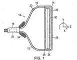
- FIG. 1 shows a cathode ray tube (CRT) 10 having a glass envelope 12 comprising a rectangular faceplate panel 14 and a tubular neck 16 connected by a rectangular funnel 18.
- the funnel 18 has an internal conductive coating (not shown) that extends from an anode button 20 to a neck 16.
- the panel 14 comprises a viewing faceplate 22 and a peripheral flange or sidewall 24 that is sealed to the funnel 18 by a glass frit 26.
- a three-color phosphor screen 28 is carried by the inner surface of the faceplate 22.
- the screen 28 is a line screen with the phosphor lines arranged in triads, each triad including a phosphor line of each of the three colors.
- a tension mask 30 is removably mounted in a predetermined spaced relation to the screen 28.
- the mask may be either a tension focus mask or a tension mask.
- An electron gun 32 (schematically shown by the dashed lines in FIG. 1) is centrally mounted within the neck 16 to generate three in-line electron beams, a center beam and two side beams, along convergent paths through the mask 30 to the screen 28.
- the tube 10 is designed to be used with an external magnetic deflection yoke, such as the yoke 34 shown in the neighborhood of the funnel to neck junction.
- the yoke 34 subjects the three beams to magnetic fields that cause the beams to scan horizontally and vertically in a rectangular raster over the screen 28.
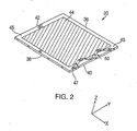
- the tension mask 30, as shown in FIG. 2, is interconnected to a peripheral frame (not shown) that includes two long sides 36 and 38, and two short sides 40 and 42.
- the two long sides 36 and 38 of the frame parallel a central major axis, X, of the tube; and the two short sides 40 and 42 parallel a central minor axis, Y, of the tube.
- the major axis and minor axis are along the plane of the mask 30.
- the tension mask 30 includes an apertured portion 44 (apertures not shown) that contains a plurality of metal strips having a multiplicity of elongated slits there between that parallel the minor axis of the mask.
- the tension mask 30 has a border 45 having an edge 47.
- FIG. 3 depicts a split foot damper 50.
- split foot damper 50 comprises a first element 52 having a first portion 56 in moveable contact with a surface of border 45 and a second portion 58 in moveable contact with an edge 47 of the border 45.
- a second element 54 having a third portion 60 in moveable contact with the surface of the border 45 and a fourth portion 62 in moveable contact with the edge 47 of the border 45.
- the first and second elements 52, 54 are connected to each other at a center region or point C that is affixed to the surface of border 45.
- the split foot damper 50 is coupled to the border 45 of mask 30 on the short sides 40,42. More specifically, split foot damper 50 is attached to the border 45, for example, by welding at the center region or point C.
- first element 52 comprises a first arm 64 having a first outer end 66 and a first inner end 68.
- a first leg 70 having a first portion 56 and second portion 58 extends downward from the first outer end 66 of first arm 64.
- the first portion 56 of first leg 70 is in moveable contact with the surface of the border 45 (See FIG. 4).
- Second portion 58 is angled below the first portion 56 and is in moveable contact with an edge 47 of the border 45.
- first and second portions 56 and 58 and between third and fourth portions 60 and 62 there is no gap 100 between first and second portions 56 and 58 and between third and fourth portions 60 and 62. Rather first portion 56 and third portion 60 are positioned so that a section of portion 56 and 60 over hang the edge 47 of the border 45. Thus, preventing second portion 58 and fourth portion 62 from contacting the edge 47 of the border 45 unless there is vibrational energy being communicated to split foot damper 50.
- Second element 54 comprises a second arm 72 having a second outer end 74 and a second inner end 76.
- a second leg 78 having a third portion 60 and a fourth portion 62 extends downward from the outer end 74 of second arm 72.
- the third portion 60 of second leg 78 is in moveable contact with the surface of the border 45.
- Fourth portion 62 is angled below third portion 60 and is in moveable contact with an edge 47 of the border 45.
- first portion 56 and third portion 60 vibrate in the plane of the mask 30, the angular bend of second portion 58 and fourth portion 62 prevent the first and third portions 56 and 60 from moving into the apertured portion 44 of the mask 30 and blocking the electron beams.
- first portion 56 and third portion 60 can be larger than second portion 58 and fourth portion 62.
- second portion 58 and fourth portion 62 can be the same size as first portion 56 and third portion 60.
- second portion 58 and fourth portion 62 can be larger than first portion 56 and third portion 60.
- the ratio in size between first and third portions 56 and 60 to second and fourth portions 58 and 62 is about a 4 to 1 ratio.
- Portion 80 connects the inner end 68 of first arm 64 to the inner end 76 of second arm 72. Portion 80 is located proximate the center of split foot damper 50. Portion 80 is affixed to the surface of the border 45 at a region or point C. Alternatively, portion 80 could be V-shaped or some other shape having a trough that contacts the surface of the border 45.
- Split foot damper 50 can be comprised of stainless steel, invar and the like. Additionally, split foot damper 50 can be fabricated from strip stock having a constant width resulting in little waste of material.
- the first arm 64 has a first plurality of apertures 84 disposed thereon.
- a ring from a first plurality of rings 86 is disposed within each aperture in the first plurality of apertures 84 and comprises a first inner ring 88 and a first outer ring 90.
- the first plurality of rings 86 are shown illustratively as being two rings but those skilled in the art will appreciate that at least one ring may be used and still fall within the scope of the invention.
- the second arm 72 has a second plurality of apertures 92 disposed thereon.
- a ring from a second plurality of rings 94 is disposed within each aperture in the second plurality of apertures 92 and comprises a second inner ring 96 and a second outer ring 98.
- the spacing of the rings on each of first and second arm 64,72 are spaced 12,7 mm (0.5 inches) apart and each of the rings is 2,5 mm (0.1 inches) in radius.
- the mask 30 When a mask 30 is subject to vibrations from external sources, the mask 30 vibrates at a predefined frequency which is linked to the length of the mask 30 and the tension of the mask 30.
- the predefined frequency is generally about 80 Hz, which is independent of the size of a television set.
- the vibrational energy is also on the border 45 of the mask.
- Split foot damper 50 is designed to match the 80 Hz frequency. Specifically, each half of split foot damper 50 is designed to a specific length, width and thickness to arrive at this frequency.
- the split foot damper 50 is tuned to the resonant frequency of the mask 30. Vibrational energy causes the mask 30 to move predominantly in the z-axis. As the mask moves in the in the z-axis first portion 56 and third portion 60 vibrate in the x-axis and the y-axis contacting the surface of the border 45 of the mask 30 and "scrubbing away" vibrational energy.
- second portion 58 and fourth portion 62 may moveably contact the edge 47 of the border 45 scrubbing away additional vibrational energy.
- vibrational energy is also transferred to the arms 64, 72 of split foot damper 50 resulting in the plurality of rings 86,94 vibrating and dissipating the vibrational energy of the mask 30.
Landscapes
- Electrodes For Cathode-Ray Tubes (AREA)
- Respiratory Apparatuses And Protective Means (AREA)
- Printing Plates And Materials Therefor (AREA)
Claims (11)
- Un tube à rayons cathodiques (10) comprenant un masque sous tension (30) et un amortisseur à base fendue (50) permettant de réduire l'énergie vibratoire dans le masque sous tension, le masque sous tension étant doté d'une bordure (45) avec un bord (47), ledit tube à rayons cathodiques étant caractérisé en ce que ledit amortisseur comprend :un premier élément (52) doté d'une première portion (56) en contact mobile avec une surface de la bordure et d'une seconde portion (58) en contact mobile avec le bord d'une bordure, ladite première portion et ladite deuxième portion étant séparées ;un deuxième élément (54) doté d'une troisième portion (60) en contact mobile avec la surface de la bordure et une quatrième portion (62) en contact mobile avec le bord de la bordure, ladite troisième portion et ladite quatrième portion étant séparées ;le premier élément étant relié au deuxième élément au niveau d'une région qui est apposée sur la surface de la bordure.
- L'appareil de la revendication 1, dans lequel le premier élément (52) est caractérisé en ce qu'il est doté d'un premier bras (64) avec une première extrémité externe (66) et une première extrémité interne (68).
- L'appareil de la revendication 1, dans lequel le second élément est caractérisé en ce qu'il est doté d'un deuxième bras (72) avec une deuxième extrémité externe (74) et une deuxième extrémité interne (76).
- L'appareil de la revendication 2, caractérisé en ce qu'il est doté d'une première jambe (70) s'étendant du premier bras et formant la première et la deuxième section.
- L'appareil de la revendication 4, caractérisé en ce qu'il est doté d'une deuxième jambe (78) s'étendant du deuxième bras et formant la troisième et la quatrième section.
- L'appareil de la revendication 1, caractérisé en ce que la première portion est plus grande que la deuxième portion.
- L'appareil de la revendication 1, caractérisé en ce que la troisième portion est plus grande que la quatrième portion.
- L'appareil de la revendication 2, caractérisé par une première pluralité d'anneaux (86) disposée dans une première pluralité d'ouvertures (84) sur le premier bras.
- L'appareil de la revendication 3, caractérisé par une deuxième pluralité d'anneaux (94) disposée dans une deuxième pluralité d'ouvertures (92) sur le deuxième bras.
- L'appareil de la revendication 1, caractérisé en ce qu'il est doté d'un espace (100) entre la première et la deuxième portion.
- L'appareil de la revendication 1, caractérisé en ce qu'il est doté d'un espace (100) entre la troisième et la quatrième portion.
Applications Claiming Priority (2)
| Application Number | Priority Date | Filing Date | Title |
|---|---|---|---|
| US09/775,228 US6520475B2 (en) | 2001-02-01 | 2001-02-01 | Split foot damper |
| US775228 | 2001-02-01 |
Publications (3)
| Publication Number | Publication Date |
|---|---|
| EP1231624A2 EP1231624A2 (fr) | 2002-08-14 |
| EP1231624A3 EP1231624A3 (fr) | 2002-10-23 |
| EP1231624B1 true EP1231624B1 (fr) | 2005-04-20 |
Family
ID=25103729
Family Applications (1)
| Application Number | Title | Priority Date | Filing Date |
|---|---|---|---|
| EP02290139A Expired - Lifetime EP1231624B1 (fr) | 2001-02-01 | 2002-01-21 | Tube à rayons cathodiques comprenant un amortisseur de vibrations pour un masque sous tension |
Country Status (8)
| Country | Link |
|---|---|
| US (1) | US6520475B2 (fr) |
| EP (1) | EP1231624B1 (fr) |
| JP (1) | JP3927826B2 (fr) |
| KR (1) | KR100419487B1 (fr) |
| CN (1) | CN1216397C (fr) |
| DE (1) | DE60203750T2 (fr) |
| MX (1) | MXPA02001106A (fr) |
| MY (1) | MY131046A (fr) |
Families Citing this family (7)
| Publication number | Priority date | Publication date | Assignee | Title |
|---|---|---|---|---|
| IT1319319B1 (it) * | 2000-11-07 | 2003-10-10 | Videocolor Spa | Tubo a raggi catodici a colori e piu' in particolare una struttura dimaschera adattata per essere mantenuta in tensione all'interno del |
| JP3752175B2 (ja) * | 2001-10-30 | 2006-03-08 | 松下電器産業株式会社 | カラー陰極線管 |
| US6710531B2 (en) * | 2001-12-21 | 2004-03-23 | Thomson Licensing S.A. | CRT having a shadow mask vibration damper |
| ITMI20030527A1 (it) * | 2003-03-19 | 2004-09-20 | Videocolor Spa | Dispositivo di mascheratura per tubo a raggi catodici |
| US20070273844A1 (en) * | 2006-05-25 | 2007-11-29 | Clark Stephan R | Support for a cantilevered lens assembly |
| US20070284185A1 (en) * | 2006-06-07 | 2007-12-13 | Foss Gary C | Damped structural panel and method of making same |
| USD774481S1 (en) * | 2014-03-25 | 2016-12-20 | Samsung Electronics Co., Ltd. | TV receiver |
Family Cites Families (14)
| Publication number | Priority date | Publication date | Assignee | Title |
|---|---|---|---|---|
| US3832592A (en) * | 1971-07-05 | 1974-08-27 | Hitachi Ltd | Mask electrode support for color picture tube |
| US3894260A (en) * | 1973-12-12 | 1975-07-08 | Zenith Radio Corp | Color selection electrode suspension system with bimetal structures having orthogonal deflection components |
| US4828202A (en) * | 1979-09-27 | 1989-05-09 | The Boeing Company | Method and apparatus for wideband vibration damping of reinforced skin structures |
| NL8603055A (nl) * | 1986-12-01 | 1988-07-01 | Philips Nv | Kleurenbeeldbuis omvattende een nagenoeg rechthoekig draagraam waaraan een schaduwmasker is bevestigd. |
| US4827179A (en) * | 1987-06-09 | 1989-05-02 | Zenith Electronics Corporation | Mask vibration damping in cathode ray tubes |
| US5214349A (en) * | 1990-10-26 | 1993-05-25 | Mitsubishi Denki Kabushiki Kaisha | Color cathode ray tube and color selection electrode device of color cathode ray tube |
| KR940003241Y1 (ko) * | 1991-08-21 | 1994-05-16 | 삼성전관 주식회사 | 칼라 음극선관의 마스크 프레임 댐퍼 |
| JPH0945256A (ja) * | 1995-08-01 | 1997-02-14 | Hitachi Ltd | シャドウマスク構体を備えたカラー陰極線管 |
| JP3189765B2 (ja) * | 1997-10-20 | 2001-07-16 | ソニー株式会社 | カラー陰極線管及びアパーチャグリル |
| KR100241598B1 (ko) * | 1997-12-01 | 2000-02-01 | 손욱 | 음극선관용 결합스프링과 그 제조방법 |
| JPH11250825A (ja) * | 1998-02-26 | 1999-09-17 | Matsushita Electric Ind Co Ltd | シャドウマスク |
| JP3300669B2 (ja) * | 1998-09-01 | 2002-07-08 | 松下電器産業株式会社 | カラー陰極線管 |
| EP1098349B1 (fr) * | 1999-11-05 | 2005-04-27 | VIDEOCOLOR S.p.A. | Structure cadre/masque ameliorée pour tube à rayons cathodiques |
| IT1319319B1 (it) * | 2000-11-07 | 2003-10-10 | Videocolor Spa | Tubo a raggi catodici a colori e piu' in particolare una struttura dimaschera adattata per essere mantenuta in tensione all'interno del |
-
2001
- 2001-02-01 US US09/775,228 patent/US6520475B2/en not_active Expired - Fee Related
-
2002
- 2002-01-21 DE DE60203750T patent/DE60203750T2/de not_active Expired - Fee Related
- 2002-01-21 EP EP02290139A patent/EP1231624B1/fr not_active Expired - Lifetime
- 2002-01-29 JP JP2002020201A patent/JP3927826B2/ja not_active Expired - Fee Related
- 2002-01-30 KR KR10-2002-0005282A patent/KR100419487B1/ko not_active Expired - Fee Related
- 2002-01-30 MX MXPA02001106A patent/MXPA02001106A/es active IP Right Grant
- 2002-01-31 MY MYPI20020351A patent/MY131046A/en unknown
- 2002-02-01 CN CN021027889A patent/CN1216397C/zh not_active Expired - Fee Related
Also Published As
| Publication number | Publication date |
|---|---|
| US6520475B2 (en) | 2003-02-18 |
| DE60203750D1 (de) | 2005-05-25 |
| JP2002251966A (ja) | 2002-09-06 |
| US20020101147A1 (en) | 2002-08-01 |
| MY131046A (en) | 2007-07-31 |
| KR100419487B1 (ko) | 2004-02-21 |
| DE60203750T2 (de) | 2006-02-02 |
| EP1231624A3 (fr) | 2002-10-23 |
| KR20020064181A (ko) | 2002-08-07 |
| CN1216397C (zh) | 2005-08-24 |
| JP3927826B2 (ja) | 2007-06-13 |
| CN1369895A (zh) | 2002-09-18 |
| MXPA02001106A (es) | 2002-09-18 |
| EP1231624A2 (fr) | 2002-08-14 |
Similar Documents
| Publication | Publication Date | Title |
|---|---|---|
| US5644192A (en) | Color picture having a tensioned mask and compliant support frame assembly | |
| EP1231624B1 (fr) | Tube à rayons cathodiques comprenant un amortisseur de vibrations pour un masque sous tension | |
| US6614155B2 (en) | Method and apparatus for reducing vibrational energy in a tension focus mask | |
| US6573645B1 (en) | Detensioning mask frame assembly for a cathode-ray tube (CRT) | |
| US7215071B2 (en) | Color cathode ray tube having a detensioning mask frame assembly | |
| EP1089311A2 (fr) | Tube cathodique couleur | |
| US6710531B2 (en) | CRT having a shadow mask vibration damper | |
| EP1294008B1 (fr) | Amortisseur à friction de vibrations pour un tube cathodique à masque tendu | |
| US6566797B2 (en) | Tension mask frame assembly having a detensioning mask support frame | |
| US6600258B2 (en) | Tension mask for a cathode-ray-tube | |
| US6566799B1 (en) | Cathode ray tubes having damper wire support springs | |
| US6700319B2 (en) | Cathode-ray tube having a tension mask with microphonics control | |
| US6794806B2 (en) | Warp-free dual compliant tension mask frame | |
| EP1235249A2 (fr) | Ensemble masque-cadre sous tension pour tube à rayons cathodiques | |
| US6777864B2 (en) | Tension mask for a cathode-ray tube with improved vibration damping | |
| US20070108883A1 (en) | Unified magnetic shielding of tensioned mask/frame assembly and internal magnetic shield | |
| EP1410414A2 (fr) | Ressort a fil metallique amortisseur pour un tube cathodique | |
| WO2006073390A1 (fr) | Tube cathodique avec des amortisseurs microphoniques | |
| WO2005119726A1 (fr) | Ecran magnetique unifie d'un ensemble cadre de masque tendu et ecran magnetique interne |
Legal Events
| Date | Code | Title | Description |
|---|---|---|---|
| PUAI | Public reference made under article 153(3) epc to a published international application that has entered the european phase |
Free format text: ORIGINAL CODE: 0009012 |
|
| AK | Designated contracting states |
Kind code of ref document: A2 Designated state(s): AT BE CH CY DE DK ES FI FR GB GR IE IT LI LU MC NL PT SE TR |
|
| AX | Request for extension of the european patent |
Free format text: AL;LT;LV;MK;RO;SI |
|
| PUAL | Search report despatched |
Free format text: ORIGINAL CODE: 0009013 |
|
| AK | Designated contracting states |
Kind code of ref document: A3 Designated state(s): AT BE CH CY DE DK ES FI FR GB GR IE IT LI LU MC NL PT SE TR |
|
| AX | Request for extension of the european patent |
Free format text: AL;LT;LV;MK;RO;SI |
|
| AKX | Designation fees paid | ||
| 17P | Request for examination filed |
Effective date: 20030410 |
|
| RBV | Designated contracting states (corrected) |
Designated state(s): DE FR GB IT |
|
| REG | Reference to a national code |
Ref country code: DE Ref legal event code: 8566 |
|
| 17Q | First examination report despatched |
Effective date: 20040211 |
|
| GRAP | Despatch of communication of intention to grant a patent |
Free format text: ORIGINAL CODE: EPIDOSNIGR1 |
|
| GRAS | Grant fee paid |
Free format text: ORIGINAL CODE: EPIDOSNIGR3 |
|
| GRAA | (expected) grant |
Free format text: ORIGINAL CODE: 0009210 |
|
| AK | Designated contracting states |
Kind code of ref document: B1 Designated state(s): DE FR GB IT |
|
| REG | Reference to a national code |
Ref country code: GB Ref legal event code: FG4D |
|
| REG | Reference to a national code |
Ref country code: IE Ref legal event code: FG4D |
|
| REF | Corresponds to: |
Ref document number: 60203750 Country of ref document: DE Date of ref document: 20050525 Kind code of ref document: P |
|
| RAP2 | Party data changed (patent owner data changed or rights of a patent transferred) |
Owner name: THOMSON LICENSING |
|
| PLBE | No opposition filed within time limit |
Free format text: ORIGINAL CODE: 0009261 |
|
| STAA | Information on the status of an ep patent application or granted ep patent |
Free format text: STATUS: NO OPPOSITION FILED WITHIN TIME LIMIT |
|
| ET | Fr: translation filed | ||
| 26N | No opposition filed |
Effective date: 20060123 |
|
| PGFP | Annual fee paid to national office [announced via postgrant information from national office to epo] |
Ref country code: DE Payment date: 20090120 Year of fee payment: 8 |
|
| PGFP | Annual fee paid to national office [announced via postgrant information from national office to epo] |
Ref country code: GB Payment date: 20081230 Year of fee payment: 8 |
|
| PGFP | Annual fee paid to national office [announced via postgrant information from national office to epo] |
Ref country code: IT Payment date: 20090127 Year of fee payment: 8 |
|
| PGFP | Annual fee paid to national office [announced via postgrant information from national office to epo] |
Ref country code: FR Payment date: 20090123 Year of fee payment: 8 |
|
| GBPC | Gb: european patent ceased through non-payment of renewal fee |
Effective date: 20100121 |
|
| REG | Reference to a national code |
Ref country code: FR Ref legal event code: ST Effective date: 20100930 |
|
| PG25 | Lapsed in a contracting state [announced via postgrant information from national office to epo] |
Ref country code: FR Free format text: LAPSE BECAUSE OF NON-PAYMENT OF DUE FEES Effective date: 20100201 |
|
| PG25 | Lapsed in a contracting state [announced via postgrant information from national office to epo] |
Ref country code: DE Free format text: LAPSE BECAUSE OF NON-PAYMENT OF DUE FEES Effective date: 20100803 |
|
| PG25 | Lapsed in a contracting state [announced via postgrant information from national office to epo] |
Ref country code: GB Free format text: LAPSE BECAUSE OF NON-PAYMENT OF DUE FEES Effective date: 20100121 |
|
| PG25 | Lapsed in a contracting state [announced via postgrant information from national office to epo] |
Ref country code: IT Free format text: LAPSE BECAUSE OF NON-PAYMENT OF DUE FEES Effective date: 20100121 |