EP1231675B1 - Connecteur à fiche et procédé de fabrication - Google Patents
Connecteur à fiche et procédé de fabrication Download PDFInfo
- Publication number
- EP1231675B1 EP1231675B1 EP02002080A EP02002080A EP1231675B1 EP 1231675 B1 EP1231675 B1 EP 1231675B1 EP 02002080 A EP02002080 A EP 02002080A EP 02002080 A EP02002080 A EP 02002080A EP 1231675 B1 EP1231675 B1 EP 1231675B1
- Authority
- EP
- European Patent Office
- Prior art keywords
- plate component
- base plate
- terminal fitting
- component
- overlapping fold
- Prior art date
- Legal status (The legal status is an assumption and is not a legal conclusion. Google has not performed a legal analysis and makes no representation as to the accuracy of the status listed.)
- Expired - Lifetime
Links
- 238000004519 manufacturing process Methods 0.000 title claims description 15
- 239000004020 conductor Substances 0.000 claims description 67
- 229910052751 metal Inorganic materials 0.000 claims description 20
- 239000002184 metal Substances 0.000 claims description 20
- 230000013011 mating Effects 0.000 claims description 8
- 238000000034 method Methods 0.000 claims 3
- 210000002105 tongue Anatomy 0.000 claims 2
- 238000005452 bending Methods 0.000 description 12
- 239000000463 material Substances 0.000 description 9
- 239000002699 waste material Substances 0.000 description 6
- 230000015572 biosynthetic process Effects 0.000 description 4
- 239000012467 final product Substances 0.000 description 2
- 229910000838 Al alloy Inorganic materials 0.000 description 1
- 229910000881 Cu alloy Inorganic materials 0.000 description 1
- 238000012986 modification Methods 0.000 description 1
- 230000004048 modification Effects 0.000 description 1
- 238000009751 slip forming Methods 0.000 description 1
Images





Classifications
-
- H—ELECTRICITY
- H01—ELECTRIC ELEMENTS
- H01R—ELECTRICALLY-CONDUCTIVE CONNECTIONS; STRUCTURAL ASSOCIATIONS OF A PLURALITY OF MUTUALLY-INSULATED ELECTRICAL CONNECTING ELEMENTS; COUPLING DEVICES; CURRENT COLLECTORS
- H01R13/00—Details of coupling devices of the kinds covered by groups H01R12/70 or H01R24/00 - H01R33/00
- H01R13/02—Contact members
- H01R13/04—Pins or blades for co-operation with sockets
-
- H—ELECTRICITY
- H01—ELECTRIC ELEMENTS
- H01R—ELECTRICALLY-CONDUCTIVE CONNECTIONS; STRUCTURAL ASSOCIATIONS OF A PLURALITY OF MUTUALLY-INSULATED ELECTRICAL CONNECTING ELEMENTS; COUPLING DEVICES; CURRENT COLLECTORS
- H01R43/00—Apparatus or processes specially adapted for manufacturing, assembling, maintaining, or repairing of line connectors or current collectors or for joining electric conductors
- H01R43/16—Apparatus or processes specially adapted for manufacturing, assembling, maintaining, or repairing of line connectors or current collectors or for joining electric conductors for manufacturing contact members, e.g. by punching and by bending
-
- Y—GENERAL TAGGING OF NEW TECHNOLOGICAL DEVELOPMENTS; GENERAL TAGGING OF CROSS-SECTIONAL TECHNOLOGIES SPANNING OVER SEVERAL SECTIONS OF THE IPC; TECHNICAL SUBJECTS COVERED BY FORMER USPC CROSS-REFERENCE ART COLLECTIONS [XRACs] AND DIGESTS
- Y10—TECHNICAL SUBJECTS COVERED BY FORMER USPC
- Y10T—TECHNICAL SUBJECTS COVERED BY FORMER US CLASSIFICATION
- Y10T29/00—Metal working
- Y10T29/49—Method of mechanical manufacture
- Y10T29/49002—Electrical device making
- Y10T29/49117—Conductor or circuit manufacturing
- Y10T29/49204—Contact or terminal manufacturing
-
- Y—GENERAL TAGGING OF NEW TECHNOLOGICAL DEVELOPMENTS; GENERAL TAGGING OF CROSS-SECTIONAL TECHNOLOGIES SPANNING OVER SEVERAL SECTIONS OF THE IPC; TECHNICAL SUBJECTS COVERED BY FORMER USPC CROSS-REFERENCE ART COLLECTIONS [XRACs] AND DIGESTS
- Y10—TECHNICAL SUBJECTS COVERED BY FORMER USPC
- Y10T—TECHNICAL SUBJECTS COVERED BY FORMER US CLASSIFICATION
- Y10T29/00—Metal working
- Y10T29/49—Method of mechanical manufacture
- Y10T29/49002—Electrical device making
- Y10T29/49117—Conductor or circuit manufacturing
- Y10T29/49204—Contact or terminal manufacturing
- Y10T29/49208—Contact or terminal manufacturing by assembling plural parts
- Y10T29/49218—Contact or terminal manufacturing by assembling plural parts with deforming
-
- Y—GENERAL TAGGING OF NEW TECHNOLOGICAL DEVELOPMENTS; GENERAL TAGGING OF CROSS-SECTIONAL TECHNOLOGIES SPANNING OVER SEVERAL SECTIONS OF THE IPC; TECHNICAL SUBJECTS COVERED BY FORMER USPC CROSS-REFERENCE ART COLLECTIONS [XRACs] AND DIGESTS
- Y10—TECHNICAL SUBJECTS COVERED BY FORMER USPC
- Y10T—TECHNICAL SUBJECTS COVERED BY FORMER US CLASSIFICATION
- Y10T29/00—Metal working
- Y10T29/49—Method of mechanical manufacture
- Y10T29/49002—Electrical device making
- Y10T29/49117—Conductor or circuit manufacturing
- Y10T29/49204—Contact or terminal manufacturing
- Y10T29/49208—Contact or terminal manufacturing by assembling plural parts
- Y10T29/49222—Contact or terminal manufacturing by assembling plural parts forming array of contacts or terminals
Definitions
- US Patent 6,077,131 discloses a male terminal which prevents to a certain degree deformation of the connection portion.
- the connection portion comprising a bottom base portion and a contact portion is bent so that the base portion is superposed by the contact portion, and side edge portions of the contact portion are bent downwards (and, optionally downwards and outwards) so as to contact the inner face of the bottom base portion.
- many bending steps are required to obtain the male terminal, thereby adding to the manufacturing costs.
- EP 0 693 798 A1 discloses a male terminal fixture in which a tab portion is folded so that its longitudinal edges face each other.
- An outwardly bulged area is provided in the bottom base portion of the tab portion in order to provide a uniform thickness of the tab, and a projection projects inwardly from the bulged area, so that the tab is prevented from deforming.
- the projection is only provided at some points along the bottom base portion. The additional step of creating the bulged area and the protrusion also increases manufacturing costs.
- the bottom base is, alas, not consistently flat.
- Said overlapping fold plate component includes a side plate element upwardly extending from one side of said base plate component in a plane substantially perpendicular to said base plate component, and a top plate element extending from said side plate element in a plane substantially parallel to said base plate component; said flatness securing plate component overlaps said base plate component and said top plate element.
- Said flatness securing plate component, said base plate component and said overlapping fold plate component are formed into a substantially roll shape in cross section, and the flatness securing plate component extends along the other side of the base plate component.
- a male terminal fitting comprising: a plate-shaped contact protrusion formed at one side of said male terminal fitting for mating with a female terminal fitting; and a conductor clamping portion located at the other side of said male terminal fitting for clamping a conductor of an electric wire;
- said plate-shape contact protrusion includes a base plate component longitudinally extending from said conduct clamping portion in an elongated plate shape, a first overlapping fold plate component laterally extending from one side of said base plate component and folded in one direction toward the other end of said base plate component to overlap with said base plate component, and a second overlapping fold plate component which extends from the other end of said base plate component and which is folded back in another direction opposed to said one direction to overlap with said base plate component; wherein said base plate component serves as a flatness securing plate component to ensure flatness conditions of said first and second overlapping fold plate components, and said base plate component (44) and said first and second overlapping fold plate components are formed into
- One end of the male terminal fitting 10 is formed with a plate-shaped contact protrusion 11, that extends in a longitudinal direction, for mating with a female terminal fitting, and the other end of the male terminal fitting 10 is formed with a conductor clamping portion 12 for clamping a conductor of an electric wire (not shown) is connected.
- a clamping body 13 Located between the plate-shaped contact protrusion 11 and the conductor clamping portion 12 is a clamping body 13.
- the flatness securing plate component 16 functions as a core element to enable the base plate component 14 and the overlapping fold plate component 15 to be held in flatness condition, respectively.
- the base plate component 14 is contiguous with the clamping body 13, the conductor clamping portion 12 and a carrier 17, and forms bottom wall portions of the clamp body 13 and the conductor clamping 12.
- a distal end of the base plate component 14 is integrally formed with a substantially triangle tongue 18 which is orientated in the longitudinal direction, with the triangle tongue18 of the base plate component 14 and another triangle tongue 18 formed at a distal end of the overlapping fold plate component 15 being bent in overlapped condition with respect to one another to form a guide portion 19.
- the overlapping fold plate component 15 is composed of a longitudinally extending side plate element 20 which extends from the one side of the base plate component 14 in a substantially perpendicular direction thereto, and a top plate element 21 contiguous with the side plate element 20 and extending from the side plate component 20 in substantially parallel to the base plate component 14, with the flatness securing plate component 16 overlapping with the base plate component 14 and the top plate element 21 to be formed in the rolled structure.
- the conductor clamping portion 12 is formed with a first pair of caulking segments 22, 22 for clamping a sheath of the electric wire, and a second pair of caulking segments 23, 23 for clamping the conductor of the electric wire. Furthermore, upon caulking operation for clamping the conductor and the sheath of the electric wire with the caulking segments 22, 22, 23, 23, the conductor of the electric wire is electrically connected to the male terminal fitting 10.
- the clamping body 13, formed between the plate-shaped contact protrusion 11 and the conductor clamping portion 12, has a tabular structure with its both sides formed with outwardly extending clamp protrusions 24, 24.
- the clamping body 13 is clamped in an inner wall of a terminal receiver chamber of a connector housing in which the male terminal fitting 10 is received, thereby avoiding the male terminal fitting 10 from being removed out from the terminal receiver chamber.
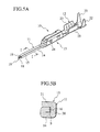
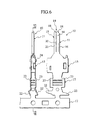
- Fig. 6 shows the male terminal fitting 10 which are formed by bending formation and the male terminal fitting formed in a developed state before bending operation, with both male terminal fittings 10 being shown as connected to the carrier 17.
- the male terminal fittings are removed from the carrier in a final step.
- a large number of arrayed chain type terminal fittings 10 are first continuously stamped out from an elongated conductive sheet material with a given width in a developed state and are then continuously formed into a final product as shown in Fig. 5A.
- there is a so-called blank area which forms a waste portion, between the adjacent male terminal fittings.
- the flatness securing plate component 16 is formed so as to longitudinally extend from the distal end of the connecting segment 12, then, an elongated sheet material in an increased width is required, with a resultant increase in the waste blank area.
- the presence of the flatness securing plate component 16 located between the base plate component 14 and the overlapping fold plate component 15 allows the conductor clamping portion 12 to have an increased strength.
- the base plate component 14 and the overlapping fold plate component 15 are not deformed to prevent central areas of the contact protrusion from being collapsed, enabling the base plate component 14 and the overlapping fold plate component 15 to remain in desired flatness conditions, respectively, to obtain a reliable electrical contact with the associated female terminal fitting.
- the other side of the base plate component 14 is folded without bending the distal end of the base plate component 14 inward, providing an ease of bending formation.
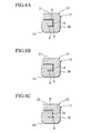
- the flatness securing plate component 16 overlaps with the base plate component 14 and the top plate element 21 in the roll shape in cross section, there are some instances where a small gap S' is created among the flatness securing plate component 16 and the base plate component 14 and the top plate element 21 due to spring back actions caused in respective bent areas.
- Fig. 8A shows a condition where small gaps S' are formed between the flatness securing plate component 16, and the base plate component 14 and the top plate element 21, respectively.
- Fig. 8B shows a condition where the small gap S' is formed between the flatness securing plate component 16 and the base plate component 14, and
- Fig. 8C shows a condition where the small gap S' is formed between the flatness securing plate component 16 and the top plate element 21.
- the flatness securing plate component 16 has been shown and described as extending from the other side of the base plate component 14, the flatness securing plate component may be modified so as to extend from the overlapping fold plate component 15.
- the space S has been shown and described as being created between the distal end of the flatness securing plate component 16 and the side plate element 20, it is preferable for the space S to have a value as small as possible to increase the surface area of the flatness securing plate component 16 for supporting the top plate element 21.
- Fig. 9A is a plan view illustrating the male terminal fitting 30 of the second preferred embodiment.
- Fig. 9B is a side view of the male terminal fitting 30 of the second preferred embodiment, and
- Fig. 9C is a cross sectional view taken on line IX-IX of Fig. 9B.
- a plate-shaped contact protrusion 31 is comprised of a base plate component 34 longitudinally extending from a conductor clamping portion 32 and made of elongated metal sheet, a first overlapping fold plate component 35 laterally extending from one side of the base plate component 34 and folded to overlap with the base plate component 34, and a second overlapping fold plate component 36 which extends from the first overlapping fold plate component 35 in substantially parallel thereto and overlaps with the first overlapping plate component 35, thereby forming a substantially S-shape in cross section.
- the first overlapping fold plate component 35 have the same function as the flatness securing plate component 16 of the first preferred embodiment to ensure flatness conditions of the base plate component 34 and the second overlapping fold plate component 36, respectively.
- the male terminal fitting 30 of the second preferred embodiment has a similar shape in structure as that of the first preferred embodiment except for the plate-shaped contact protrusion 31.
- the base plate component 34 is contiguous with bottom walls of the conductor clamping portion 32 and the clamping body 33 and is connected to a carrier.
- a distal end of the base plate component 34 is integrally formed with a substantially triangular tongue 38, which is bent with a substantially triangular tongue 38 formed in the same shape at a distal end of the second overlapping fold plate component 36 to be formed into a guide portion 39.
- the male terminal fitting 30 is comprised of the first overlapping fold plate component 35 interposed between the base plate component 34 and the second overlapping fold plate component 36, the conductor clamping portion 32 has an increased strength. Therefore, even when the male terminal fitting 30 is applied with external press forces during press forming operation, no deformation is caused in the base plate component 34 and the second overlapping fold plate component 36 while precluding central areas of the contact protrusion from being collapsed. Thus, it is possible for the base plate component 34 and the second overlapping fold plate component 36 to have a remarkably increased strength in a reliable manner.
- the second overlapping fold plate component 36 which serves as the flatness securing plate component, is formed so as to extend from the first overlapping fold plate component 35 in the substantially parallel to the base plate component 34, resulting in a decrease in waste material while avoiding an increase in the material cost.
- the planar-shaped securing plate component 36, the base plate component 34 and the second overlapping fold plate component 36 overlaps with respect to one another in the substantially S-shape in cross section. Accordingly, when the plate-shaped contact protrusion 31 is tightly fitted to a female terminal fitting, an electrical contact is ensured between the plate-shaped contact protrusion 31 and the female terminal fitting in a reliable manner using the spring back actions of the respective folded portions.
- Fig. 10A is a plan view illustrating the male terminal fitting 40 of the third preferred embodiment.
- Fig. 10B is a side view of the male terminal fitting 40 of the third preferred embodiment, and
- Fig. 10C is a cross sectional view taken on line X-X of Fig. 10B.
- a plate-shaped contact protrusion 41 is comprised of a base plate component 44 longitudinally extending from a conductor clamping portion 42 and made of elongated metal sheet, a first overlapping fold plate component 45 laterally extending from one side of the base plate component 44 and folded to overlap with the base plate component 44, and a second overlapping fold plate component 46 which laterally extends from the other side of base plate component 44 and overlaps with the base plate component 44 in a substantially parallel thereto and in an orientation opposed to the first overlapping fold plate component 45, thereby forming a substantially S-shape in cross section.
- the base plate component 44 which functions as the flatness securing plate component, ensure the first overlapping fold plate component 45 and the second overlapping fold plate component 46 to have desired flatness conditions, respectively.
- the male terminal fitting 40 of the second preferred embodiment has a similar shape in structure as that of the first preferred embodiment except for the plate-shaped contact protrusion 41.
- the base plate component 44 is contiguous with bottom walls of the conductor clamping portion 42 and the clamping body 43 and is connected to a carrier.
- a distal end of the base plate component 44 is integrally formed with a substantially triangular tongue 48, which is bent with a substantially triangular tongue 48 formed in the same shape at a distal end of the second overlapping fold plate component 46 to be formed into a guide portion 49.
- the conductor clamping portion 42 has an increased strength. Therefore, even when the male terminal fitting 40 is exerted with the external press forces during the press forming operation, no deformation is caused in the first and second overlapping fold plate components 45, 46 while precluding central areas of the contact protrusion from being collapsed. Thus, it is possible for the first and second overlapping fold plate components 45, 46 to have a remarkably increased strength in a reliable manner.
- the base plate component 44 serving as the flatness securing plate component is overlapped between the first and second overlapping fold plate components 45, 46 in three layers to form a substantially S-shape configuration in cross section. Accordingly, when the plate-shaped contact protrusion 41 is tightly fitted into a female terminal fitting, an electrical contact is ensured between the plate-shaped contact protrusion 41 and the female terminal fitting in a reliable manner using the spring back actions of the respective bent portions.
- Fig. 11A is a plan view illustrating the male type terminal fitting 50 of the fourth preferred embodiment.
- Fig. 11B is a side view of the male terminal fitting 50 of the fourth preferred embodiment
- Fig. 11C is a cross sectional view taken on line XI-XI of Fig. 11B.
- Fig. 11D is an enlarged cross sectional view of a guide portion taken on line XII-XII of Fig. 11A.
- a plate-shaped contact protrusion 51 is comprised of a base plate component 54 longitudinally extending from a conductor clamping portion 52 and made of elongated metal sheet, an overlapping fold plate component 55 laterally extending from one side of the base plate component 54 and folded to overlap with the base plate component 54, and a flatness securing plate component 56 which laterally extends from the other side of base plate component 54 and overlaps with the base plate component 54 and the overlapping fold plate component 5, thereby forming a substantially roll shape in cross section.
- the flatness securing plate component 56 ensures the base plate component 54 and the overlapping fold plate component 55 to have desired flatness conditions, respectively.
- the guide portion 59 is formed in a tapered shape that has two pairs of opposed surfaces which are tapered toward respective distal ends.
- the male terminal fitting 50 of the fourth preferred embodiment has a similar shape in structure as that of the first preferred embodiment except for the guide portion 59.
- the base plate component 54 is contiguous with bottom walls of the conductor clamping portion 52 and the clamping body 53 and is connected to a carrier.
- the male terminal fitting 50 is comprised of the flatness securing plate component 56 which overlaps with the base plate component 54 and the overlapping fold plate component 55, no empty space is internally created to allow the guide portion 59 to have an increased strength.
- the presence of the guide portion with the increased strength enables the guide portion 59 to be prevented from being deformed even when the male terminal fitting 50 is repeatedly fitted into the female terminal fitting.
- the flatness securing plate component 56 has been shown and described as extending from the other side of the base plate component 54, the flatness securing plate component may extend from the overlapping fold plate component 55.
Landscapes
- Engineering & Computer Science (AREA)
- Manufacturing & Machinery (AREA)
- Manufacturing Of Electrical Connectors (AREA)
- Coupling Device And Connection With Printed Circuit (AREA)
- Connections By Means Of Piercing Elements, Nuts, Or Screws (AREA)
Claims (12)
- Raccord de terminal mâle (10) comprenant:une protubérance de contact en forme de plaque (11) formée au niveau d'un côté dudit raccord de terminal mâle pour s'adapter à un raccord de terminal femelle, etune partie de serrage de conducteur (12) située au niveau de l'autre côté dudit raccord de terminal mâle destinée à serrer un conducteur d'un fil électrique,dans lequel ladite protubérance de contact en forme de plaque comprend un composant de plaque de base (14) s'étendant longitudinalement depuis ladite partie de serrage de conducteur suivant une forme de plaque allongée, un composant de plaque pliable de recouvrement (15) s'étendant latéralement d'un côté dudit composant de plaque de base et plié pour recouvrir ledit composant de plaque de base, et un composant de plaque de garantie de planéité (16) recouvrant ledit composant de plaque de base et ledit composant de plaque pliable de recouvrement pour garantir des conditions de planéité dudit composant de plaque de base et dudit composant de plaque pliable de recouvrement,
caractérisé en ce que
ledit composant de plaque pliable de recouvrement comprend un élément de plaque latérale (20) s'étendant vers le haut depuis un côté dudit composant de plaque de base (14) dans un plan sensiblement perpendiculaire audit composant de plaque de base, et un élément de plaque supérieure (21) s'étendant depuis ledit élément de plaque latérale dans un plan sensiblement parallèle audit composant de plaque de base,
ledit composant de plaque de garantie de planéité (16) recouvre ledit composant de plaque de base et ledit élément de plaque supérieure,
ledit composant de plaque de garantie de planéité (16), ledit composant de plaque de base (14) et ledit composant de plaque pliable de recouvrement (15) se présentent sensiblement sous une forme de rouleau en coupe transversale, et
le composant de plaque de garantie de planéité (16) s'étend le long de l'autre côté du composant de plaque de base (14). - Raccord de terminal mâle selon la revendication 1, dans lequel :ladite protubérance de contact en forme de plaque (11) présente une extrémité distale dotée d'une partie de guidage (19) composée de languettes sensiblement rectangulaires (18) qui sont repliées l'une vers l'autre.
- Raccord de terminal mâle selon la revendication 1, dans lequel :ladite protubérance de contact en forme de plaque (51) présente une extrémité distale dotée d'une partie de guidage conique (59).
- Raccord de terminal mâle (30) comprenant :une protubérance de contact en forme de plaque (31) formée au niveau d'un premier côté dudit raccord de terminal mâle pour s'adapter à un raccord de terminal femelle, etune partie de serrage de conducteur (32) située au niveau de l'autre côté dudit raccord de terminal mâle destinée à serrer un conducteur d'un fil électrique,dans lequel ladite protubérance de contact en forme de plaque comprend un composant de plaque de base (34) s'étendant longitudinalement depuis ladite partie de serrage de conducteur suivant une forme de plaque allongée, un premier composant de plaque pliable de recouvrement (35) s'étendant latéralement depuis un premier côté dudit composant de plaque de base et plié dans une première direction orientée vers l'autre extrémité dudit composant de plaque de base pour recouvrir ledit composant de plaque de base, et un second composant de plaque pliable de recouvrement (36) qui s'étend depuis ledit premier composant de plaque pliable de recouvrement à une position proche de l'autre extrémité dudit composant de plaque de base et qui est rabattu dans une autre direction opposée à ladite première direction pour recouvrir ledit premier composant de plaque pliable de recouvrement,
où ledit premier composant de plaque pliable de recouvrement sert de composant de plaque de garantie de planéité pour garantir les conditions de planéité dudit composant de plaque de base et dudit second composant de plaque pliable de recouvrement, et
ledit composant de plaque de base (34) et lesdits premier et second composants de plaques pliables de recouvrement (35, 36) se présentent sensiblement sous une forme de S en coupe transversale. - Raccord de terminal de type mâle selon la revendication 4, dans lequel :ladite protubérance de contact en forme de plaque (31) présente une extrémité distale dotée d'une partie de guidage (39) composée de protubérances sensiblement rectangulaires (38) qui sont repliées l'une vers l'autre.
- Raccord de terminal mâle selon la revendication 4, dans lequel :ladite protubérance de contact en forme de plaque présente une extrémité distale dotée d'une partie de guidage conique.
- Raccord de terminal mâle (40) comprenant:une protubérance de contact en forme de plaque (41) formée au niveau d'un premier côté dudit raccord de terminal mâle pour s'adapter à un raccord de terminal femelle, etune partie de serrage de conducteur (42) située au niveau de l'autre côté dudit raccord de terminal mâle destinée à serrer un conducteur d'un fil électrique,dans lequel ladite protubérance de contact en forme de plaque comprend un composant de plaque de base (44) s'étendant longitudinalement depuis ladite partie de serrage de conducteur suivant une forme de plaque allongée, un premier composant de plaque pliable de recouvrement (45) s'étendant latéralement depuis un premier côté dudit composant de plaque de base et plié dans une première direction orientée vers l'autre extrémité dudit composant de plaque de base pour recouvrir ledit composant de plaque de base, et un second composant de plaque pliable de recouvrement (46) qui s'étend depuis l'autre extrémité dudit composant de plaque de base et qui est rabattu dans une autre direction opposée à ladite première direction pour recouvrir ledit composant de plaque de base,
où ledit composant de plaque de base sert de composant de plaque de garantie de planéité pour garantir les conditions de planéité desdits premier et second composants de plaques pliables de recouvrement, et
ledit composant de plaque de base (44) et lesdits premier et second composants de plaques pliables de recouvrement (45, 46) se présentent sensiblement sous une forme de S en coupe transversale. - Raccord de terminal mâle selon la revendication 7, dans lequel:ladite protubérance de contact en forme de plaque (41) présente une extrémité distale dotée d'une partie de guidage (49) composée de languettes sensiblement rectangulaires (48) qui sont repliées l'une vers l'autre.
- Raccord de terminal mâle selon la revendication 7, dans lequel :ladite protubérance de contact en forme de plaque présente une extrémité distale dotée d'une partie de guidage conique.
- Procédé de fabrication d'un raccord de terminal mâle (10) selon la revendication 1, ledit procédé comprenant:la préparation d'une ébauche d'une feuille de métal conductrice allongée,l'estampage de ladite feuille de métal conductrice allongée pour former une pluralité de raccords de terminaux disposés à la suite, dans des états développés, qui sont reliés de façon solidaire à un élément de support, chacun desdits raccords de terminaux comprenant une partie de serrage de conducteur (12) s'étendant depuis ledit élément de support, un corps de serrage relié à ladite partie de serrage de conducteur, et une protubérance de contact en forme de plaque (11) qui est composée d'un composant de plaque de base (14) s'étendant longitudinalement depuis ladite partie de serrage de conducteur par l'intermédiaire dudit corps de serrage, d'un composant de plaque pliable de recouvrement (15) s'étendant latéralement d'un premier côté dudit composant de plaque de base, et d'un composant de plaque de garantie de planéité (16) s'étendant latéralement depuis l'autre côté de ladite plaque de base, etle formage de ladite partie de serrage de conducteur, dudit corps de serrage et de ladite protubérance de contact en forme de plaque pour adopter des formes finales respectives,où, après ladite étape de formage, ledit composant de plaque de garantie de planéité garantit les conditions de planéité dudit composant de plaque de base et dudit composant de plaque pliable de recouvrement.
- Procédé de fabrication d'un raccord de terminal mâle (30) selon la revendication 4, ledit procédé comprenant:la préparation d'une ébauche d'une feuille de métal conductrice allongée,l'estampage de ladite feuille de métal conductrice allongée pour former une pluralité de raccords de terminaux disposés à la suite, dans des états développés, qui sont reliés de façon solidaire à un élément de support, chacun desdits raccords de terminaux comprenant une partie de serrage de conducteur (32) s'étendant depuis ledit élément de support, un corps de serrage relié à ladite partie de serrage de conducteur, et une protubérance de contact en forme de plaque (31) qui est composée d'un composant de plaque de base (34) s'étendant longitudinalement depuis ladite partie de serrage de conducteur par l'intermédiaire dudit corps de serrage, d'un premier composant de plaque pliable de recouvrement (35) s'étendant latéralement d'un premier côté dudit composant de plaque de base, et d'un second composant de plaque pliable de recouvrement (36) s'étendant latéralement depuis ledit premier composant de plaque pliable de recouvrement, etle formage de ladite partie de serrage de conducteur, dudit corps de serrage et de ladite protubérance de contact en forme de plaque pour adopter des formes finales respectives,où, après ladite étape de formage, ledit premier composant de plaque pliable de recouvrement sert de composant de plaque de garantie de planéité pour garantir les conditions de planéité dudit composant de plaque de base et desdits premier et second composants de plaques pliables de recouvrement.
- Procédé de fabrication d'un raccord de terminal mâle (40) selon la revendication 7, ledit procédé comprenant :la préparation d'une ébauche d'une feuille de métal conductrice allongée,l'estampage de ladite feuille de métal conductrice allongée pour former une pluralité de raccords de terminaux disposés à la suite, dans des états développés, qui sont reliés de façon solidaire à un élément de support, chacun desdits raccords de terminaux comprenant une partie de serrage de conducteur (42) s'étendant depuis ledit élément de support, un corps de serrage relié à ladite partie de serrage de conducteur, et une protubérance de contact en forme de plaque (41) qui est composée d'un composant de plaque de base (44) s'étendant longitudinalement depuis ladite partie de serrage de conducteur par l'intermédiaire dudit corps de serrage, d'un premier composant de plaque pliable de recouvrement (45) s'étendant latéralement depuis un premier côté dudit composant de plaque de base, et d'un second composant de plaque pliable de recouvrement (46) s'étendant latéralement depuis l'autre côté dudit composant de plaque de base, etle formage de ladite partie de serrage de conducteur, dudit corps de serrage et de ladite protubérance de contact en forme de plaque pour adopter des formes finales respectives,où, après ladite étape de formage, ledit composant de plaque de base sert de composant de garantie de planéité pour garantir les conditions de planéité desdits premier et second composants de plaques pliables de recouvrement.
Applications Claiming Priority (6)
| Application Number | Priority Date | Filing Date | Title |
|---|---|---|---|
| JP2001036001 | 2001-02-13 | ||
| JP2001036001 | 2001-02-13 | ||
| JP2001146830 | 2001-05-16 | ||
| JP2001146830 | 2001-05-16 | ||
| JP2001238137A JP2003036911A (ja) | 2001-02-13 | 2001-08-06 | 雄型端子金具 |
| JP2001238137 | 2001-08-06 |
Publications (3)
| Publication Number | Publication Date |
|---|---|
| EP1231675A2 EP1231675A2 (fr) | 2002-08-14 |
| EP1231675A3 EP1231675A3 (fr) | 2004-12-22 |
| EP1231675B1 true EP1231675B1 (fr) | 2007-08-22 |
Family
ID=27345974
Family Applications (1)
| Application Number | Title | Priority Date | Filing Date |
|---|---|---|---|
| EP02002080A Expired - Lifetime EP1231675B1 (fr) | 2001-02-13 | 2002-02-11 | Connecteur à fiche et procédé de fabrication |
Country Status (5)
| Country | Link |
|---|---|
| US (2) | US6752669B2 (fr) |
| EP (1) | EP1231675B1 (fr) |
| JP (1) | JP2003036911A (fr) |
| CN (1) | CN1213521C (fr) |
| DE (1) | DE60221928T2 (fr) |
Cited By (1)
| Publication number | Priority date | Publication date | Assignee | Title |
|---|---|---|---|---|
| EP3970239A1 (fr) * | 2019-05-17 | 2022-03-23 | Amphenol-Tuchel Electronics GmbH | Élément de contact enfichable, produit semi-fini pour la fabrication d'un élément de contact enfichable et procédé pour la fabrication d'un élément de contact enfichable |
Families Citing this family (23)
| Publication number | Priority date | Publication date | Assignee | Title |
|---|---|---|---|---|
| JP2003036910A (ja) * | 2001-07-19 | 2003-02-07 | Yazaki Corp | コネクタ端子 |
| JP2003036909A (ja) * | 2001-07-19 | 2003-02-07 | Yazaki Corp | コネクタ端子 |
| JP3823811B2 (ja) * | 2001-11-22 | 2006-09-20 | 住友電装株式会社 | 雄側タブ |
| TWD104096S1 (zh) | 2002-03-20 | 2005-04-11 | 日本壓著端子製造股份有限公司 | 壓接端子 |
| KR100768738B1 (ko) | 2005-02-02 | 2007-10-22 | 스미토모 덴소 가부시키가이샤 | 수형 단자 피팅과, 수형 단자 피팅용 플레이트 재료,그리고 수형 단자 피팅의 형성 방법 |
| US7024767B1 (en) * | 2005-03-14 | 2006-04-11 | Giga-Byte Technology Co., Ltd. | Method for making terminal |
| JP5087485B2 (ja) * | 2008-07-15 | 2012-12-05 | 矢崎総業株式会社 | 端子製造方法 |
| JP5429100B2 (ja) * | 2010-08-06 | 2014-02-26 | 住友電装株式会社 | 端子金具 |
| JP6193122B2 (ja) * | 2010-08-20 | 2017-09-06 | デルフィ・インターナショナル・オペレーションズ・ルクセンブルク・エス・アー・エール・エル | 雄電気端子 |
| EP2650972B1 (fr) * | 2010-12-08 | 2016-03-16 | Furukawa Electric Co., Ltd. | Borne à sertir, structure de connexion et procédé de production de ces dernières |
| DE102011017787A1 (de) | 2011-04-29 | 2012-10-31 | Robert Bosch Gmbh | Kontaktelement zur elektrischen Direktkontaktierung von Leiterplatten |
| JP5682519B2 (ja) * | 2011-09-14 | 2015-03-11 | 住友電装株式会社 | 端子金具 |
| DE102011082806A1 (de) * | 2011-09-16 | 2013-03-21 | Zf Friedrichshafen Ag | Verfahren und Vorrichtung zur Diagnose von Fehlern in Bauteilen von Fahrwerksystemen von Kraftfahrzeugen |
| JP2014225388A (ja) * | 2013-05-16 | 2014-12-04 | 住友電装株式会社 | 雄端子金具 |
| JP5644919B1 (ja) * | 2013-08-26 | 2014-12-24 | 第一精工株式会社 | コネクタ端子およびその製造方法 |
| DE102013016814A1 (de) * | 2013-10-10 | 2015-04-16 | Yamaichi Electronics Deutschland Gmbh | Elektrisches Kontaktelement, Steckverbinder und Herstellungsverfahren |
| JP6143194B2 (ja) * | 2014-03-25 | 2017-06-07 | 住友電装株式会社 | 雄端子金具 |
| KR101723042B1 (ko) | 2014-12-11 | 2017-04-05 | 주식회사 유라코퍼레이션 | 메일 단자 핀구조 |
| KR101858138B1 (ko) * | 2017-02-20 | 2018-05-15 | (주)우주일렉트로닉스 | 접촉 신뢰성이 향상된 커넥터 장치 |
| US20210408708A1 (en) * | 2020-06-26 | 2021-12-30 | I-Pex Inc. | Terminal |
| JP1680780S (fr) * | 2020-07-07 | 2021-03-08 | ||
| JP2023027576A (ja) * | 2021-08-17 | 2023-03-02 | 住友電装株式会社 | 雄端子金具、及びコネクタ |
| JP1765486S (ja) * | 2023-03-14 | 2024-03-13 | コネクタ端子 |
Family Cites Families (13)
| Publication number | Priority date | Publication date | Assignee | Title |
|---|---|---|---|---|
| US17757A (en) * | 1857-07-07 | Heber g | ||
| US1982501A (en) * | 1932-06-13 | 1934-11-27 | Harry A Douglas | Connecting means |
| US2738484A (en) * | 1954-06-17 | 1956-03-13 | Burroughs Corp | Solderless terminal |
| US4298242A (en) * | 1979-02-23 | 1981-11-03 | Trw Inc. | Electrical socket contact |
| JPS56169377A (en) | 1980-05-30 | 1981-12-26 | Nippon Telegr & Teleph Corp <Ntt> | Light semiconductor device |
| SE8901230D0 (sv) * | 1988-08-01 | 1989-04-07 | Aweidmueller Gmbh & Co C | Foerfarande foer framstaellning av med ett isoleringselement foersedda kontaktorgan saasom kontakthylsor och kabelskor och deras anbringande paa avisolerade ledaraendar, samt enligt foerfarandet framstaellda kontaktorgan |
| JPH0339275A (ja) | 1989-07-07 | 1991-02-20 | Seiki Ind Co Ltd | 熱転写印刷装置 |
| US5495669A (en) * | 1993-09-21 | 1996-03-05 | Zierick Manufacturing Corp. | Method of making box contacts |
| US5666723A (en) * | 1994-04-22 | 1997-09-16 | Yazaki Corporation | Method of producing connector terminal |
| JP2734994B2 (ja) * | 1994-07-20 | 1998-04-02 | 住友電装株式会社 | 雄型端子金具 |
| JP3177144B2 (ja) * | 1996-02-14 | 2001-06-18 | 矢崎総業株式会社 | 雄型端子 |
| JPH10128572A (ja) | 1996-10-28 | 1998-05-19 | Nittetsu Boshoku Kk | 金属の極薄板の溶接方法 |
| JP2003036910A (ja) * | 2001-07-19 | 2003-02-07 | Yazaki Corp | コネクタ端子 |
-
2001
- 2001-08-06 JP JP2001238137A patent/JP2003036911A/ja not_active Abandoned
-
2002
- 2002-02-01 US US10/060,300 patent/US6752669B2/en not_active Expired - Lifetime
- 2002-02-09 CN CNB021047383A patent/CN1213521C/zh not_active Expired - Fee Related
- 2002-02-11 EP EP02002080A patent/EP1231675B1/fr not_active Expired - Lifetime
- 2002-02-11 DE DE60221928T patent/DE60221928T2/de not_active Expired - Lifetime
-
2004
- 2004-04-20 US US10/829,308 patent/US7114253B2/en not_active Expired - Lifetime
Cited By (1)
| Publication number | Priority date | Publication date | Assignee | Title |
|---|---|---|---|---|
| EP3970239A1 (fr) * | 2019-05-17 | 2022-03-23 | Amphenol-Tuchel Electronics GmbH | Élément de contact enfichable, produit semi-fini pour la fabrication d'un élément de contact enfichable et procédé pour la fabrication d'un élément de contact enfichable |
Also Published As
| Publication number | Publication date |
|---|---|
| CN1213521C (zh) | 2005-08-03 |
| EP1231675A2 (fr) | 2002-08-14 |
| DE60221928D1 (de) | 2007-10-04 |
| US6752669B2 (en) | 2004-06-22 |
| DE60221928T2 (de) | 2008-04-30 |
| US20020111082A1 (en) | 2002-08-15 |
| US20040224576A1 (en) | 2004-11-11 |
| CN1371144A (zh) | 2002-09-25 |
| JP2003036911A (ja) | 2003-02-07 |
| US7114253B2 (en) | 2006-10-03 |
| EP1231675A3 (fr) | 2004-12-22 |
Similar Documents
| Publication | Publication Date | Title |
|---|---|---|
| EP1231675B1 (fr) | Connecteur à fiche et procédé de fabrication | |
| JP3823811B2 (ja) | 雄側タブ | |
| US6077131A (en) | Male terminal | |
| EP3582332B1 (fr) | Borne de raccordement et structure de raccordement de borne | |
| US6851989B2 (en) | Terminal fitting with plural resilient contact pieces and pressing portion for holding base ends of resilient contact pieces together | |
| EP1035616B1 (fr) | Cosse à sertir pour des plaquettes à circuits flexibles et structure à serissage de fil | |
| CN101645544A (zh) | 端子接头及其形成方法 | |
| JP2002083639A (ja) | 端子金具のタブ | |
| US7059921B2 (en) | Female electrical contact | |
| WO2014073287A1 (fr) | Cosse mâle | |
| JPH0883636A (ja) | 雌端子金具 | |
| EP1278270B1 (fr) | Terminal de connexion | |
| JP2006179209A (ja) | 雌端子及びコネクタ | |
| JP3316198B2 (ja) | 雄型コンタクト | |
| JPH11297371A (ja) | バスバーのレーザ溶接構造 | |
| EP2683037B1 (fr) | Borne de connecteur et son procédé de fabrication | |
| EP2575215B1 (fr) | Pose de terminal | |
| EP2654140B1 (fr) | Fermeture de jointure d'un contact de prise | |
| JP2008066271A (ja) | 端子原板、連続端子、端子原板の製造方法、連続端子の製造方法及び端子付き電線の製造方法 | |
| US6325658B2 (en) | Insulation-displacement terminal fitting and production method therefor | |
| EP3800750B1 (fr) | Contact électrique | |
| JP3014944B2 (ja) | 端子金具及び端子金具の製造方法 | |
| JPH1154162A (ja) | 圧接端子 | |
| HK1030836B (en) | Flexible printed circuit board crimp terminal and crimping structure for core therewith | |
| JP2005093268A (ja) | 圧接端子 |
Legal Events
| Date | Code | Title | Description |
|---|---|---|---|
| PUAI | Public reference made under article 153(3) epc to a published international application that has entered the european phase |
Free format text: ORIGINAL CODE: 0009012 |
|
| 17P | Request for examination filed |
Effective date: 20020211 |
|
| AK | Designated contracting states |
Kind code of ref document: A2 Designated state(s): AT BE CH CY DE DK ES FI FR GB GR IE IT LI LU MC NL PT SE TR |
|
| AX | Request for extension of the european patent |
Free format text: AL;LT;LV;MK;RO;SI |
|
| PUAL | Search report despatched |
Free format text: ORIGINAL CODE: 0009013 |
|
| AK | Designated contracting states |
Kind code of ref document: A3 Designated state(s): AT BE CH CY DE DK ES FI FR GB GR IE IT LI LU MC NL PT SE TR |
|
| AX | Request for extension of the european patent |
Extension state: AL LT LV MK RO SI |
|
| AKX | Designation fees paid |
Designated state(s): DE FR GB SE |
|
| GRAP | Despatch of communication of intention to grant a patent |
Free format text: ORIGINAL CODE: EPIDOSNIGR1 |
|
| RAP1 | Party data changed (applicant data changed or rights of an application transferred) |
Owner name: YAZAKI CORPORATION |
|
| GRAS | Grant fee paid |
Free format text: ORIGINAL CODE: EPIDOSNIGR3 |
|
| GRAA | (expected) grant |
Free format text: ORIGINAL CODE: 0009210 |
|
| AK | Designated contracting states |
Kind code of ref document: B1 Designated state(s): DE FR GB SE |
|
| REG | Reference to a national code |
Ref country code: GB Ref legal event code: FG4D |
|
| REF | Corresponds to: |
Ref document number: 60221928 Country of ref document: DE Date of ref document: 20071004 Kind code of ref document: P |
|
| REG | Reference to a national code |
Ref country code: SE Ref legal event code: TRGR |
|
| ET | Fr: translation filed | ||
| PLBE | No opposition filed within time limit |
Free format text: ORIGINAL CODE: 0009261 |
|
| STAA | Information on the status of an ep patent application or granted ep patent |
Free format text: STATUS: NO OPPOSITION FILED WITHIN TIME LIMIT |
|
| 26N | No opposition filed |
Effective date: 20080526 |
|
| REG | Reference to a national code |
Ref country code: FR Ref legal event code: PLFP Year of fee payment: 15 |
|
| REG | Reference to a national code |
Ref country code: FR Ref legal event code: PLFP Year of fee payment: 16 |
|
| REG | Reference to a national code |
Ref country code: FR Ref legal event code: PLFP Year of fee payment: 17 |
|
| PGFP | Annual fee paid to national office [announced via postgrant information from national office to epo] |
Ref country code: GB Payment date: 20200129 Year of fee payment: 19 Ref country code: DE Payment date: 20200129 Year of fee payment: 19 Ref country code: SE Payment date: 20200210 Year of fee payment: 19 |
|
| PGFP | Annual fee paid to national office [announced via postgrant information from national office to epo] |
Ref country code: FR Payment date: 20200113 Year of fee payment: 19 |
|
| REG | Reference to a national code |
Ref country code: DE Ref legal event code: R119 Ref document number: 60221928 Country of ref document: DE |
|
| REG | Reference to a national code |
Ref country code: SE Ref legal event code: EUG |
|
| GBPC | Gb: european patent ceased through non-payment of renewal fee |
Effective date: 20210211 |
|
| PG25 | Lapsed in a contracting state [announced via postgrant information from national office to epo] |
Ref country code: SE Free format text: LAPSE BECAUSE OF NON-PAYMENT OF DUE FEES Effective date: 20210212 |
|
| PG25 | Lapsed in a contracting state [announced via postgrant information from national office to epo] |
Ref country code: DE Free format text: LAPSE BECAUSE OF NON-PAYMENT OF DUE FEES Effective date: 20210901 Ref country code: FR Free format text: LAPSE BECAUSE OF NON-PAYMENT OF DUE FEES Effective date: 20210228 Ref country code: GB Free format text: LAPSE BECAUSE OF NON-PAYMENT OF DUE FEES Effective date: 20210211 |