EP1231677B1 - Connecteur étanche et son joint en caoutchouc - Google Patents
Connecteur étanche et son joint en caoutchouc Download PDFInfo
- Publication number
- EP1231677B1 EP1231677B1 EP02002170A EP02002170A EP1231677B1 EP 1231677 B1 EP1231677 B1 EP 1231677B1 EP 02002170 A EP02002170 A EP 02002170A EP 02002170 A EP02002170 A EP 02002170A EP 1231677 B1 EP1231677 B1 EP 1231677B1
- Authority
- EP
- European Patent Office
- Prior art keywords
- rubber
- rubber stopper
- stopper
- waterproof
- waterproof connector
- Prior art date
- Legal status (The legal status is an assumption and is not a legal conclusion. Google has not performed a legal analysis and makes no representation as to the accuracy of the status listed.)
- Expired - Lifetime
Links
- 229920001971 elastomer Polymers 0.000 title claims description 113
- 239000005060 rubber Substances 0.000 title claims description 113
- 150000001875 compounds Chemical class 0.000 claims description 21
- 229920002379 silicone rubber Polymers 0.000 claims description 15
- 239000004014 plasticizer Substances 0.000 claims description 14
- 239000007767 bonding agent Substances 0.000 claims description 13
- BJQHLKABXJIVAM-UHFFFAOYSA-N bis(2-ethylhexyl) phthalate Chemical compound CCCCC(CC)COC(=O)C1=CC=CC=C1C(=O)OCC(CC)CCCC BJQHLKABXJIVAM-UHFFFAOYSA-N 0.000 claims description 12
- 239000004803 Di-2ethylhexylphthalate Substances 0.000 claims description 8
- 239000000463 material Substances 0.000 claims description 7
- XNGIFLGASWRNHJ-UHFFFAOYSA-L phthalate(2-) Chemical compound [O-]C(=O)C1=CC=CC=C1C([O-])=O XNGIFLGASWRNHJ-UHFFFAOYSA-L 0.000 claims description 7
- 239000000470 constituent Substances 0.000 claims description 6
- 125000002227 silylidyne group Chemical group [H][Si]#* 0.000 claims description 6
- LFQSCWFLJHTTHZ-UHFFFAOYSA-N Ethanol Chemical compound CCO LFQSCWFLJHTTHZ-UHFFFAOYSA-N 0.000 claims description 5
- 238000010276 construction Methods 0.000 claims description 4
- 125000005375 organosiloxane group Chemical group 0.000 claims description 3
- 125000001140 1,4-phenylene group Chemical group [H]C1=C([H])C([*:2])=C([H])C([H])=C1[*:1] 0.000 claims description 2
- 238000010438 heat treatment Methods 0.000 claims description 2
- 238000007789 sealing Methods 0.000 description 15
- 238000000465 moulding Methods 0.000 description 12
- 239000000126 substance Substances 0.000 description 12
- 230000006835 compression Effects 0.000 description 10
- 238000007906 compression Methods 0.000 description 10
- 239000011347 resin Substances 0.000 description 8
- 229920005989 resin Polymers 0.000 description 8
- BZHJMEDXRYGGRV-UHFFFAOYSA-N Vinyl chloride Chemical compound ClC=C BZHJMEDXRYGGRV-UHFFFAOYSA-N 0.000 description 7
- 239000000565 sealant Substances 0.000 description 7
- 238000011156 evaluation Methods 0.000 description 6
- 229920000459 Nitrile rubber Polymers 0.000 description 5
- 238000000034 method Methods 0.000 description 5
- 239000004020 conductor Substances 0.000 description 4
- 230000007423 decrease Effects 0.000 description 4
- 239000000945 filler Substances 0.000 description 4
- 238000003780 insertion Methods 0.000 description 4
- 230000037431 insertion Effects 0.000 description 4
- XNGIFLGASWRNHJ-UHFFFAOYSA-N phthalic acid Chemical compound OC(=O)C1=CC=CC=C1C(O)=O XNGIFLGASWRNHJ-UHFFFAOYSA-N 0.000 description 4
- 239000003963 antioxidant agent Substances 0.000 description 3
- 230000003078 antioxidant effect Effects 0.000 description 3
- 239000003795 chemical substances by application Substances 0.000 description 3
- 238000007796 conventional method Methods 0.000 description 3
- 230000008878 coupling Effects 0.000 description 3
- 238000010168 coupling process Methods 0.000 description 3
- 238000005859 coupling reaction Methods 0.000 description 3
- 229920002943 EPDM rubber Polymers 0.000 description 2
- VYPSYNLAJGMNEJ-UHFFFAOYSA-N Silicium dioxide Chemical compound O=[Si]=O VYPSYNLAJGMNEJ-UHFFFAOYSA-N 0.000 description 2
- 230000000694 effects Effects 0.000 description 2
- 229920001296 polysiloxane Polymers 0.000 description 2
- 229920000915 polyvinyl chloride Polymers 0.000 description 2
- 239000004800 polyvinyl chloride Substances 0.000 description 2
- 229910052710 silicon Inorganic materials 0.000 description 2
- 239000010703 silicon Substances 0.000 description 2
- 238000012360 testing method Methods 0.000 description 2
- MSYCOOMLZQPCAL-UHFFFAOYSA-N 3,4-bis(8-methylnonyl)phthalic acid Chemical compound CC(C)CCCCCCCC1=CC=C(C(O)=O)C(C(O)=O)=C1CCCCCCCC(C)C MSYCOOMLZQPCAL-UHFFFAOYSA-N 0.000 description 1
- 206010067482 No adverse event Diseases 0.000 description 1
- 239000002202 Polyethylene glycol Substances 0.000 description 1
- XUIMIQQOPSSXEZ-UHFFFAOYSA-N Silicon Chemical compound [Si] XUIMIQQOPSSXEZ-UHFFFAOYSA-N 0.000 description 1
- 230000002411 adverse Effects 0.000 description 1
- 125000003545 alkoxy group Chemical group 0.000 description 1
- 150000007514 bases Chemical class 0.000 description 1
- 229910052799 carbon Inorganic materials 0.000 description 1
- 239000006229 carbon black Substances 0.000 description 1
- 125000002843 carboxylic acid group Chemical group 0.000 description 1
- 238000002788 crimping Methods 0.000 description 1
- 239000003431 cross linking reagent Substances 0.000 description 1
- 125000004122 cyclic group Chemical group 0.000 description 1
- 230000003247 decreasing effect Effects 0.000 description 1
- 230000001419 dependent effect Effects 0.000 description 1
- 125000003700 epoxy group Chemical group 0.000 description 1
- 238000002474 experimental method Methods 0.000 description 1
- 125000000524 functional group Chemical group 0.000 description 1
- 238000004519 manufacturing process Methods 0.000 description 1
- 230000013011 mating Effects 0.000 description 1
- 125000001997 phenyl group Chemical group [H]C1=C([H])C([H])=C(*)C([H])=C1[H] 0.000 description 1
- 125000000843 phenylene group Chemical group C1(=C(C=CC=C1)*)* 0.000 description 1
- 239000000049 pigment Substances 0.000 description 1
- 229920001223 polyethylene glycol Polymers 0.000 description 1
- 150000003377 silicon compounds Chemical class 0.000 description 1
- 239000000377 silicon dioxide Substances 0.000 description 1
- 238000005476 soldering Methods 0.000 description 1
- 229920003051 synthetic elastomer Polymers 0.000 description 1
- XLYOFNOQVPJJNP-UHFFFAOYSA-N water Substances O XLYOFNOQVPJJNP-UHFFFAOYSA-N 0.000 description 1
- 150000003751 zinc Chemical class 0.000 description 1
Images

Classifications
-
- H—ELECTRICITY
- H01—ELECTRIC ELEMENTS
- H01R—ELECTRICALLY-CONDUCTIVE CONNECTIONS; STRUCTURAL ASSOCIATIONS OF A PLURALITY OF MUTUALLY-INSULATED ELECTRICAL CONNECTING ELEMENTS; COUPLING DEVICES; CURRENT COLLECTORS
- H01R13/00—Details of coupling devices of the kinds covered by groups H01R12/70 or H01R24/00 - H01R33/00
- H01R13/46—Bases; Cases
- H01R13/52—Dustproof, splashproof, drip-proof, waterproof, or flameproof cases
- H01R13/5205—Sealing means between cable and housing, e.g. grommet
-
- H—ELECTRICITY
- H01—ELECTRIC ELEMENTS
- H01R—ELECTRICALLY-CONDUCTIVE CONNECTIONS; STRUCTURAL ASSOCIATIONS OF A PLURALITY OF MUTUALLY-INSULATED ELECTRICAL CONNECTING ELEMENTS; COUPLING DEVICES; CURRENT COLLECTORS
- H01R43/00—Apparatus or processes specially adapted for manufacturing, assembling, maintaining, or repairing of line connectors or current collectors or for joining electric conductors
- H01R43/005—Apparatus or processes specially adapted for manufacturing, assembling, maintaining, or repairing of line connectors or current collectors or for joining electric conductors for making dustproof, splashproof, drip-proof, waterproof, or flameproof connection, coupling, or casing
Definitions
- the present invention relates to a rubber stopper according to the preamble of claim 1 and the preamble of claim 2.
- a rubber stopper of the above-mentioned type is known, for example, from DE 3836679A.
- a waterproof connector has a rubber stopper disposed between the connector and a covered cable to provide a waterproof seal therebetween.
- the waterproof stoppers there are two types of the waterproof stoppers, one of which is an independent rubber tubular stopper associated with each of the covered cables.
- the other type is a rubber stopper seat having a plurality of through holes each receiving the covered cable.
- reference numeral 1 designates an independent rubber tubular stopper.
- the stopper has a through hole 1a at a middle thereof, into which a covered cable 2 is inserted. An covering layer 2a of the cable 2 is partially removed so that a conductor 2b is exposed. Then, the conductor 2b of the covered cable 2 is connected to a wire crimping barrel 3b of a terminal 3 by press-fitting, soldering, or the like.
- the terminal 3 has a rubber stopper coupling barrel 3c at a base portion thereof, which is bent to hold the rubber tubular stopper 1.
- the rubber tubular stopper 1 has a lip 1b to prevent disengagement of the stopper 1 from the barrel 3b.
- the rubber stopper 1 and the terminal 3 connected to the covered cable 2 are inserted into a terminal insertion chamber (not shown) of a housing 4 of the waterproof connector.
- the terminal 3 is locked to the terminal chamber by engaging a locking piece (not shown) formed in the terminal chamber with a hooking shoulder 3d of the terminal 3.
- a watertight seal is accomplished between an inner surface of the terminal chamber and the covered cable 2 by a resilient sealing portion 1c of the rubber tubular stopper 1.
- the rubber tubular stopper includes an oleo-rubber (or an oleo-silicon-rubber) as a major constituent, a crosslinking agent, a filler, etc. to achieve a sufficient compression ratio.
- the compression ratio is designed to be normally about 15 to 40%, preferably 20 to 40%.
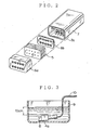
- FIG. 2 illustrates a seat-type rubber stopper.
- the seat-type rubber stopper engages with a waterproof hood provided in a terminal insertion side of a waterproof connector.
- the rubber stopper is provided for a plurality of covered cables associated with the connector.
- Japanese Patent Application Publication No. H. 9-511864 discloses such an art in which a seat-type rubber stopper has a sealant piece sandwiched by two comparatively hard wall pieces.
- Such a conventional seat-type rubber stopper has a plurality of through holes for covered cables associated with a waterproof connector.
- Each through hole should have an inner diameter to seal each covered cable.
- a molding pin for forming the through hole should have a diameter less than 0.6 mm. The small diameter frequently causes a breakage of the pins, impeding a stable forming of the through holes.
- the Japanese Patent application Publication No. H. 9-5118644 proposes an art of a seat-type rubber stopper as illustrated in FIG. 2.
- the seat-type rubber stopper has a plurality of gel sealant pieces 5 sandwiched between two hard wall pieces 6a(a case in this example) and 6b.
- the sealant piece 5 can easily seal covered cables.
- the wall piece 6a holds the gel sealant pieces 5.
- the wall pieces 6a and 6b are inserted into a terminal insertion side waterproof hood 7a of a waterproof connector housing 7.
- the waterproof connector rubber stopper having the soft gel sealant pieces that decrease in the compression ratio due to a thermal history can not be used in an automobile engine room of a high temperature condition. Moreover, the three piece construction of the rubber tubular stopper is disadvantageous in forming and productivity of the waterproof connector.
- an object of the invention is to provide a rubber stopper of a waterproof connector, the rubber stopper being able to keep a sufficient sealing property even in use at a comparatively high temperature.
- a first aspect of the invention is a rubber stopper having the features of claim 1. Further according to this first aspect, the invention provides a rubber stopper having the features of claim 2. Further embodiments of the invention are described in the dependent claims.
- the waterproof connector having thus configured rubber stopper can keep a sufficient sealing property even when the rubber stopper has decreased in the compression ratio thereof due to a thermal history. Because, the thermal history bonds the rubber stopper to the cable to allow a sufficient sealing threbetween.
- the rubber stopper of the waterproof connector Since the rubber stopper of the waterproof connector has no bonding property before its thermal history. Thus, no interruption is made in an assembling work of the waterproof connector to pass the covered cable through the rubber stopper.
- the embodiment described in Claim 3 provides a high sealing property.
- the material is an oleo-rubber that includes an organic rubber as a major constituent and a di-2-ethylhexyl phthalate and/or a high-grade alcohol phthalate.
- the embodiment described in Claim 4 provides a considerably high sealing property after heating of the rubber stopper.
- the material is an oleo-rubber that includes a compound comprising at least one of silylidyne groups.
- a second aspect of the invention is a waterproof connector having the waterproof rubber stopper according to the invention.
- a rubber stopper used in a waterproof connector according to the present invention includes preferably an oleo-rubber as a base material to obtain a high waterproof performance.
- an oleo-rubber is a general organic rubber like an acrylonitrile-butadiene rubber and an oleo-ethylene-propylene-diene rubber or may be a silicon rubber like an oleo-silicon rubber.
- An organic rubber of a non-silicon rubber group having a heat resisting property like an oleo-acrylonitrile-butadiene rubber or an oleo-ethylene propylene diene rubber is used particularly to have no adverse effects on a relay contact.
- a plasticizer is preferably added to the organic rubber soluble mutually with the covering layer of the covered cable to provide a bonding property to the organic rubber.
- the plasticizer is preferably a di-2-ethylhexyl phthalate (DOP) that achieves a sufficient waterproof property even a small amount addition thereof.
- DOP di-2-ethylhexyl phthalate
- the organic rubber includes 0.5 to 50 weight units of a plasticizer soluble mutually with the covering layer relative to 100 weight units of a basic compound.
- the plasticizer of 10 to 30 weight units is further preferable. A less than 0.5 weight units of the plasticizer can not provide a sufficient bonding property, and more than 50 weight units of the plasticizer disadvantageously decrease a heat resisting property of the rubber.
- the plasticizer may be a di-2-ethylhexyl phthalate or a high-grade alcohol phthalate like a di-isodecyl phthalic acid (DIDP).
- DIDP di-isodecyl phthalic acid
- a silicon rubber is a basic material
- an addition of a di-2-ethylhexyl phthalate or a high-grade alcohol phthalate to the silicon rubber has an adverse effects on a heat resisting property of the rubber.
- Such a silicon rubber may be mixed with a bonding agent to bond the covering layer of the covered cable to the rubber stopper when heated to provides a sufficient waterproof property thereof.
- the bonding agent may be a compound including at least one of silylidyne groups (Si-H groups) to bond the covering layer to the waterproof rubber stopper but the compound normally includes one to ten of silylidyne groups.
- the bonding agent including at least one of functional groups selected from an epoxy group, an alkoxyl group, and an anhydrous carboxylic acid group in addition to a silylidyne group provides a higher water-resisting property for a long period.
- Such a compound is a straight-chain or cyclic organosiloxane oligomer including silicones of which a number is more than one and less than 21, or an organic silicon compound like an organosiloxane oligomer of phenyl or phenylene construction having 2 to 20 silicones of a straight-chain (including branches)or cyclic configuration.
- the addition quantity of the bonding agent relative to 100 weight units of the silicon rubber compound is more than 0.1 weight units and less than 20 weight units .
- a less than 0.1 weight units of the bonding agent can not provide a sufficient bonding property, and more than 20 weight units of the bonding agent possibly cause the disadvantage that the rubber is stuck to a molding die during a forming process of the rubber.
- the addition quantity of the bonding agent is more than 6 weight units and less than 15 weight units.
- the rubber compound for the waterproof connector rubber stopper according to the present invention may include a curing agent, a curing accelerating agent, an antioxidant, a pigment, a filler (for a resiliency adjustment), etc., an addition ratio of which is limited not to degrade the effect of the present invention.
- An oleo-acrylonitrile butadiene rubber compound (called as a NBR compound hereinafter) of 100 weight units, which is an organic rubber compound including constituents described in Table 1, is mixed with 10 weight units of a di-2-ethylhexil phthalate (DOP) to be kneaded by a kneader.
- the DOP is a plasticizer soluble mutually with a vinyl chloride resin constituting a covering layer of a covered cable.
- an independent rubber tubular stopper A was formed by a conventional method in use of a molding die and had been kept at 170°C for six minutes.
- An oleo-silicon rubber compound (DY32-3050u produced by Toray Dou Cornning Silicon Rubber Corporation) of 100 weight units was mixed with 6 weight units of a bonding agent to be kneaded by a tandem roll.
- the bonding agent is a straight-chain organosiloxane oligomer of a p-phenylene construction.
- the oligomer has a silicon having four branches to join three silylidyne groups.
- the oligomer is a compound (a product of Toray Dou Cornning Silicon Rubber Corporation) shown by a chemical formula (1) to bond the covering layer of the covered cable to the waterproof rubber stopper when heated.
- an independent rubber tubular stopper B was formed by using a molding die in a conventional method and had been kept at 170°C for four minutes.
- rubber tubular stoppers C and D were formed to have the same shape as the rubber tubular stoppers A and B.
- the rubber tubular stopper C was not mixed with a di-2-ethylhexil phthalate, and the rubber tubular stopper D was not mixed with a compound shown by the chemical formula (1).
- Each of the rubber tubular stoppers A to D was formed into a vinyl chloride resin tube having a compression ratio of 12% so as to receive a vinyl chloride resin covered cable having a conductor sectional area of 0.13mm 2 . Then, an experimental waterproof connector was defined to have a connector housing with eight poles and was connected to seven covered cables.
- the connector has a waterproof connector housing 4 formed with a coupling hood 4a for mating with an opposed connector.
- the coupling hood 4a is closed by a waterproof plug 8, and, as illustrated in FIG. 3, the waterproof connector is lowered into a water bath 9 up to a depth of about 10 cm.
- an inside pressure of the waterproof connector was increased step by step at a rate of 9.8 kPa per 30 seconds by using a vinyl chloride tube 10, while an air leakage of the waterproof connector was monitored.
- a result of the experiment showed that all the waterproof connectors experienced no air leakage even a pressure of 200 kPa to prove a sufficient water-resisting property of the connectors.
- the waterproof connector having the waterproof rubber stopper A or C made of an organic rubber had been exposed in an air of 80°C for 500 hours to give a thermal history.
- the waterproof connector having the waterproof rubber stopper B or D made of a silicon rubber had been exposed in an air of 120°C for 1,000 hours to give a thermal history.
- the thermal history bonds the waterproof rubber stopper A or B to the covered cable.
- Table 2 shows that the waterproof connectors having the rubber tubular stopper A or B according to the present invention maintains a sufficient airtight seal property after the thermal history as compared with a standard airtight seal property at 100 kPa.
- the rubber tubular stoppers A and B according to the present invention could be used in a waterproof connector disposed in a high temperature location like an engine room of an automobile.
- the rubber tubular stoppers A and B have an initial compression ratio of 12% so that the through hole receiving the covered cable can have an inner diameter larger than a conventional one.
- a molding pin for the through holes can be repeatedly used without any damage of the pin, allowing a stable molding work thereof.
- Embodiments 4 and 5 NBR Compound 100 100 100 (Weight Units) DOP 30 60 (Weight Units) DIDP 20 (Weight Units) Initial over over over waterproof property 200kPa 200Kpa 200kPa Waterproof property over after thermal history 200kPa 30kPa 160kPa Note: In Embodiments 4 and 5, air bubbles occurred at a sealing portion between the rubber stopper and the connector housing.
- the phthalic acid di-isodecyl which is a high-grade alcohol phthalate can be successfully used as well as the di-2-ethylhexyl phthalate.
- the phthalic acid di-isodecyl which is a high-grade alcohol phthalate can be successfully used as well as the di-2-ethylhexyl phthalate.
- the addition ratios of compounds having chemical formula (1) were varied as described in Table 4, or, in place of the compound shown by the chemical formula (1), another bonding agent defined by chemical formula (2) was applied.
- the another bonding agent is a cyclic organosiloxane oligomer (a product of by Toray Dou Cornning Silicon Rubber Corporation) .
- Rubber tubular stoppers were molded so as to include the bonding agent so that the rubber stoppers could be bonded to the covering layers of the covered cables when heated. Then, waterproof connectors were assembled in use of the tubular stoppers similarly to the aforementioned method, and an evaluation test result of thus configured waterproof connectors is shown in Table 4.
- Table 4 shows that the compound of chemical formula (2) can be used as well as the compound of chemical formula (1).
- the present invention can provide a waterproof connector rubber stopper having a larger compression ratio with a sufficient water-resisting property.
- the rubber stopper can maintain the water-resisting property even after a long-time thermal history and is improved in a stable productivity.
Landscapes
- Connector Housings Or Holding Contact Members (AREA)
- Sealing Material Composition (AREA)
Claims (7)
- Un organe d'obturation en élastomère (1) utilisable dans un connecteur étanche à l'eau, l'organe d'obturation en élastomère (1) pouvant être placé entre un câble revêtu (2) et un boîtier de connecteur (4) du connecteur étanche à l'eau, caractérisé en ce que l'organe d'obturation en élastomère (1) est constitué d'un élastomère de silicone mélangé à un agent de liaison pour lier l'organe d'obturation en élastomère (1) à une couche de revêtement (2a) du câble revêtu (2) quand l'organe d'obturation en élastomère (1) est exposé à une histoire thermique pendant son utilisation dans un endroit où la température est élevée, comme dans un compartiment moteur d'une automobile.
- Un organe d'obturation en élastomère (1) utilisable dans un connecteur étanche à l'eau, l'organe d'obturation en élastomère (1) pouvant être placé entre un câble revêtu (2) et un boîtier de connecteur (4) du connecteur étanche à l'eau, caractérisé en ce que l'organe d'obturation en élastomère (1) est constitué d'un élastomère organique auquel un plastifiant soluble dans une couche de revêtement (2a) du câble revêtu (2) est ajouté pour lier l'organe d'obturation en élastomère (1) à la couche de revêtement (2a) du câble revêtu (2) quand l'organe d'obturation en élastomère (1) est exposé à une histoire thermique pendant son utilisation dans un endroit où la température est élevée, comme dans un compartiment moteur d'une automobile.
- L'organe d'obturation en élastomère (1) selon la revendication 2, dans lequel le matériau est un oléoélastomère qui inclut un élastomère organique comme constituant principal et un phtalate de di-2-éthylhexyle et/ou un phtalate à haute teneur en alcool.
- L'organe d'obturation en élastomère (1) selon la revendication 1, dans lequel le matériau est un oléoélastomère qui inclut un composé comprenant au moins un des groupes de silylidyne.
- L'organe d'obturation en élastomère (1) selon la revendication 1 ou 2, dans lequel une température de chauffage pendant l'histoire thermique est plus élevée que la température à laquelle l'organe d'obturation en élastomère (1) peut être assemblé dans le connecteur étanche à l'eau.
- L'organe d'obturation en élastomère (1) selon la revendication 1, dans lequel l'élastomère de silicone inclut un oligomère d'organosiloxane à chaîne droite d'une structure de p-phénylène ou un oligomère d'organosiloxane cyclique.
- Un connecteur étanche à l'eau ayant un organe d'obturation étanche à l'eau en élastomère selon l'une des revendications 1 à 6.
Applications Claiming Priority (2)
| Application Number | Priority Date | Filing Date | Title |
|---|---|---|---|
| JP2001031084A JP2002237350A (ja) | 2001-02-07 | 2001-02-07 | 防水コネクタ用ゴム栓および防水コネクタ部 |
| JP2001031084 | 2001-02-07 |
Publications (3)
| Publication Number | Publication Date |
|---|---|
| EP1231677A2 EP1231677A2 (fr) | 2002-08-14 |
| EP1231677A3 EP1231677A3 (fr) | 2004-02-04 |
| EP1231677B1 true EP1231677B1 (fr) | 2006-10-18 |
Family
ID=18895214
Family Applications (1)
| Application Number | Title | Priority Date | Filing Date |
|---|---|---|---|
| EP02002170A Expired - Lifetime EP1231677B1 (fr) | 2001-02-07 | 2002-01-29 | Connecteur étanche et son joint en caoutchouc |
Country Status (4)
| Country | Link |
|---|---|
| US (1) | US20020148633A1 (fr) |
| EP (1) | EP1231677B1 (fr) |
| JP (1) | JP2002237350A (fr) |
| DE (1) | DE60215404T2 (fr) |
Families Citing this family (8)
| Publication number | Priority date | Publication date | Assignee | Title |
|---|---|---|---|---|
| JP3682865B2 (ja) * | 2001-08-01 | 2005-08-17 | 矢崎総業株式会社 | 防水コネクタの防水栓 |
| JP2006302850A (ja) * | 2005-04-25 | 2006-11-02 | Yazaki Corp | 防水パッキンとそれを用いた防水コネクタ及びその製造方法 |
| US7581988B2 (en) * | 2006-06-30 | 2009-09-01 | Perceptron, Inc. | Detachable coupling for a remote inspection device |
| US8653365B1 (en) * | 2009-01-23 | 2014-02-18 | Claude W. Mixon | Overfill warning wiring system for tank trucks |
| JP5541331B2 (ja) | 2012-04-20 | 2014-07-09 | 日立金属株式会社 | 複合ハーネス |
| EP2731203B1 (fr) * | 2012-08-29 | 2018-05-09 | Nexans | Procédé de recouvrement imperméable d'un emplacement de liaison entre un conducteur électrique et un élément de contact |
| DE102022200170B4 (de) | 2022-01-10 | 2023-11-16 | Volkswagen Aktiengesellschaft | Steckverbindungen mit selbstverschweißender Dichtung und Verfahren zur Herstellung einer solchen Steckverbindung |
| KR102664866B1 (ko) * | 2022-04-13 | 2024-05-09 | 전영식 | 심해용 수중 커넥터 및 그 제조 방법 |
Citations (2)
| Publication number | Priority date | Publication date | Assignee | Title |
|---|---|---|---|---|
| DE3836679A1 (de) * | 1988-10-28 | 1990-05-03 | Rehau Ag & Co | Verfahren zum gas- und fluessigkeitsdichten verschliessen von rohrfoermigen bauteilen |
| US5720629A (en) * | 1996-10-16 | 1998-02-24 | The Whitaker Corporation | Sealed electrical connector |
Family Cites Families (10)
| Publication number | Priority date | Publication date | Assignee | Title |
|---|---|---|---|---|
| US3027589A (en) * | 1959-07-29 | 1962-04-03 | Machinery Service Inc | Apparatus for simultaneously changing the spacing of a series of closure members for containers |
| US3555171A (en) * | 1968-07-29 | 1971-01-12 | Robert L Larson | Cable connection insulator and seal |
| US4179319A (en) * | 1977-01-24 | 1979-12-18 | Raychem Corporation | Heat recoverable article and methods using same |
| US4266844A (en) * | 1979-08-20 | 1981-05-12 | Bolt Associates, Inc. | High strength submersible electrical cable and connector assembly |
| EP0229102B1 (fr) * | 1985-05-02 | 1994-01-19 | RAYCHEM CORPORATION (a Delaware corporation) | Joint d'etancheite pour cables |
| US4874324A (en) * | 1988-08-03 | 1989-10-17 | Westinghouse Electric Corp. | Underwater electrical connector |
| US5354210A (en) * | 1991-08-23 | 1994-10-11 | The Whitaker Corporation | Sealant compositions and sealed electrical connectors |
| WO1998021798A1 (fr) * | 1996-11-15 | 1998-05-22 | Minnesota Mining And Manufacturing Company | Systemes et procedes pour obturation etanche par adhesion |
| JP3311638B2 (ja) * | 1997-05-22 | 2002-08-05 | 矢崎総業株式会社 | 被覆導体導出部の防水方法 |
| US6482036B1 (en) * | 2002-06-13 | 2002-11-19 | Blaine L. Broussard | Waterproof electrical connector |
-
2001
- 2001-02-07 JP JP2001031084A patent/JP2002237350A/ja active Pending
-
2002
- 2002-01-18 US US10/050,170 patent/US20020148633A1/en not_active Abandoned
- 2002-01-29 DE DE60215404T patent/DE60215404T2/de not_active Expired - Lifetime
- 2002-01-29 EP EP02002170A patent/EP1231677B1/fr not_active Expired - Lifetime
Patent Citations (2)
| Publication number | Priority date | Publication date | Assignee | Title |
|---|---|---|---|---|
| DE3836679A1 (de) * | 1988-10-28 | 1990-05-03 | Rehau Ag & Co | Verfahren zum gas- und fluessigkeitsdichten verschliessen von rohrfoermigen bauteilen |
| US5720629A (en) * | 1996-10-16 | 1998-02-24 | The Whitaker Corporation | Sealed electrical connector |
Also Published As
| Publication number | Publication date |
|---|---|
| JP2002237350A (ja) | 2002-08-23 |
| DE60215404D1 (de) | 2006-11-30 |
| US20020148633A1 (en) | 2002-10-17 |
| EP1231677A2 (fr) | 2002-08-14 |
| DE60215404T2 (de) | 2007-08-23 |
| EP1231677A3 (fr) | 2004-02-04 |
Similar Documents
| Publication | Publication Date | Title |
|---|---|---|
| US6521160B2 (en) | Multipolar waterproof connector | |
| US3880487A (en) | Low cost sealed connector | |
| EP1231677A2 (fr) | Connecteur étanche et son joint en caoutchouc | |
| US20060099842A1 (en) | Waterproof connector and seal member | |
| MXPA04005041A (es) | Conjunto de conector electrico separable. | |
| EP0711006B1 (fr) | Connecteur étanche à l'eau et méthode pour son assemblage | |
| JPH08138795A (ja) | 防水コネクタ | |
| JPH08222316A (ja) | 防水コネクタハウジングおよびその製造方法 | |
| JP2003234138A (ja) | コネクタ | |
| CN118539239B (zh) | 连接器及锂电驱动产品 | |
| JP2002081555A (ja) | ゲートバルブ装置及びその製造方法 | |
| US11043773B2 (en) | Electrical connector | |
| US20250007202A1 (en) | Receptacle system with a housing pot made from soft material | |
| US20020113378A1 (en) | Packing | |
| US20060154516A1 (en) | Connector overmold spacer | |
| US20230155320A1 (en) | Electrical conductor for conducting electrical current through a housing and method for manufacturing the same | |
| US10530091B2 (en) | Water-tight partition wall bushing for plug connectors | |
| US20200373700A1 (en) | Wire connector | |
| EP2121837B1 (fr) | Composition en résine flexible et partie d'étanchéité pour connecteur résistant à l'eau | |
| CN222563109U (zh) | 固定结构及暖通系统 | |
| KR20130021356A (ko) | 라미네이터용 패킹 | |
| JP2001068206A (ja) | コネクタ及びその製造方法 | |
| JP3179994U (ja) | 電気コネクター | |
| US20230059621A1 (en) | Foamable cross-linkable thermoplastic material, connector and manufacturing method thereof | |
| JP2003234143A (ja) | コネクタ |
Legal Events
| Date | Code | Title | Description |
|---|---|---|---|
| PUAI | Public reference made under article 153(3) epc to a published international application that has entered the european phase |
Free format text: ORIGINAL CODE: 0009012 |
|
| AK | Designated contracting states |
Kind code of ref document: A2 Designated state(s): AT BE CH CY DE DK ES FI FR GB GR IE IT LI LU MC NL PT SE TR |
|
| AX | Request for extension of the european patent |
Free format text: AL;LT;LV;MK;RO;SI |
|
| PUAL | Search report despatched |
Free format text: ORIGINAL CODE: 0009013 |
|
| AK | Designated contracting states |
Kind code of ref document: A3 Designated state(s): AT BE CH CY DE DK ES FI FR GB GR IE IT LI LU MC NL PT SE TR |
|
| AX | Request for extension of the european patent |
Extension state: AL LT LV MK RO SI |
|
| 17P | Request for examination filed |
Effective date: 20040611 |
|
| 17Q | First examination report despatched |
Effective date: 20040722 |
|
| AKX | Designation fees paid |
Designated state(s): DE FR GB |
|
| GRAP | Despatch of communication of intention to grant a patent |
Free format text: ORIGINAL CODE: EPIDOSNIGR1 |
|
| GRAS | Grant fee paid |
Free format text: ORIGINAL CODE: EPIDOSNIGR3 |
|
| GRAA | (expected) grant |
Free format text: ORIGINAL CODE: 0009210 |
|
| AK | Designated contracting states |
Kind code of ref document: B1 Designated state(s): DE FR GB |
|
| REG | Reference to a national code |
Ref country code: GB Ref legal event code: FG4D |
|
| REF | Corresponds to: |
Ref document number: 60215404 Country of ref document: DE Date of ref document: 20061130 Kind code of ref document: P |
|
| ET | Fr: translation filed | ||
| RAP2 | Party data changed (patent owner data changed or rights of a patent transferred) |
Owner name: YAZAKI CORPORATION |
|
| PLBE | No opposition filed within time limit |
Free format text: ORIGINAL CODE: 0009261 |
|
| STAA | Information on the status of an ep patent application or granted ep patent |
Free format text: STATUS: NO OPPOSITION FILED WITHIN TIME LIMIT |
|
| 26N | No opposition filed |
Effective date: 20070719 |
|
| REG | Reference to a national code |
Ref country code: FR Ref legal event code: PLFP Year of fee payment: 15 |
|
| REG | Reference to a national code |
Ref country code: FR Ref legal event code: PLFP Year of fee payment: 16 |
|
| REG | Reference to a national code |
Ref country code: FR Ref legal event code: PLFP Year of fee payment: 17 |
|
| PGFP | Annual fee paid to national office [announced via postgrant information from national office to epo] |
Ref country code: FR Payment date: 20181213 Year of fee payment: 18 |
|
| PGFP | Annual fee paid to national office [announced via postgrant information from national office to epo] |
Ref country code: DE Payment date: 20190115 Year of fee payment: 18 Ref country code: GB Payment date: 20190123 Year of fee payment: 18 |
|
| REG | Reference to a national code |
Ref country code: DE Ref legal event code: R119 Ref document number: 60215404 Country of ref document: DE |
|
| GBPC | Gb: european patent ceased through non-payment of renewal fee |
Effective date: 20200129 |
|
| PG25 | Lapsed in a contracting state [announced via postgrant information from national office to epo] |
Ref country code: FR Free format text: LAPSE BECAUSE OF NON-PAYMENT OF DUE FEES Effective date: 20200131 Ref country code: DE Free format text: LAPSE BECAUSE OF NON-PAYMENT OF DUE FEES Effective date: 20200801 Ref country code: GB Free format text: LAPSE BECAUSE OF NON-PAYMENT OF DUE FEES Effective date: 20200129 |