EP1231780A2 - Bildaufnahmevorrichtung - Google Patents
Bildaufnahmevorrichtung Download PDFInfo
- Publication number
- EP1231780A2 EP1231780A2 EP02002647A EP02002647A EP1231780A2 EP 1231780 A2 EP1231780 A2 EP 1231780A2 EP 02002647 A EP02002647 A EP 02002647A EP 02002647 A EP02002647 A EP 02002647A EP 1231780 A2 EP1231780 A2 EP 1231780A2
- Authority
- EP
- European Patent Office
- Prior art keywords
- image pickup
- image
- lens
- point
- pickup apparatus
- Prior art date
- Legal status (The legal status is an assumption and is not a legal conclusion. Google has not performed a legal analysis and makes no representation as to the accuracy of the status listed.)
- Ceased
Links
Images


Classifications
-
- H—ELECTRICITY
- H04—ELECTRIC COMMUNICATION TECHNIQUE
- H04N—PICTORIAL COMMUNICATION, e.g. TELEVISION
- H04N23/00—Cameras or camera modules comprising electronic image sensors; Control thereof
- H04N23/50—Constructional details
- H04N23/54—Mounting of pick-up tubes, electronic image sensors, deviation or focusing coils
-
- H—ELECTRICITY
- H04—ELECTRIC COMMUNICATION TECHNIQUE
- H04N—PICTORIAL COMMUNICATION, e.g. TELEVISION
- H04N23/00—Cameras or camera modules comprising electronic image sensors; Control thereof
- H04N23/50—Constructional details
- H04N23/55—Optical parts specially adapted for electronic image sensors; Mounting thereof
-
- H—ELECTRICITY
- H04—ELECTRIC COMMUNICATION TECHNIQUE
- H04N—PICTORIAL COMMUNICATION, e.g. TELEVISION
- H04N23/00—Cameras or camera modules comprising electronic image sensors; Control thereof
- H04N23/60—Control of cameras or camera modules
- H04N23/698—Control of cameras or camera modules for achieving an enlarged field of view, e.g. panoramic image capture
Definitions
- This invention relates to an image pickup apparatus which picks up images of an image pickup object, for example, of a celestial hemispheric space over a wide range and stitches the images to each other to form a single image with a reduced parallax between the images.
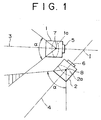
- a plurality of cameras 1, 2, ... are disposed at equal distances in a circumferential direction along a circle centered at a viewpoint I and are fixed with optical axes 3, 4, ... of lenses 1a, 2a, ... of the cameras 1, 2, ... directed in radial directions as seen in FIG. 1.
- individual images picked up by the cameras 1, 2, ... are stitched to each other at positions over which they overlap with each other to allow image pickup over the overall circumference.
- Image pickup elements 5, 6, ... such as CCDs are provided at rear ends rearwardly of the lenses 1a, 2a, ... of the cameras 1, 2, ..., respectively.
- the cameras 1, 2, ... are located at positions at which each of them simply picks up an image of part of the image pickup object, and no particular countermeasure for solving the problem of the parallax described above is provided.
- the parallax makes an obstacle to stitching of overlapping locations of picked up images after the image pickup is completed, and the images cannot be stitched well into a good image.
- lens barrels of the cameras are physically restricted in terms of the arrangement relative to each other, and it is difficult to arrange the cameras in a closely neighboring relationship to each other. Therefore, a parallax is liable to appear between images picked up by the cameras.
- an image pickup apparatus comprising a plurality of image pickup means for individually picking up images of a plurality of divisional image pickup objects of an image pickup object extending over a wide range, and processing means for receiving image information from the image pickup means and processing the image information to produce a single image by stitching images presented by the image information, the image pickup means being disposed such that, where a point at which an extension of a straight line component in an object space of a selected one of principal rays passing the center of an aperture stop for a lens set provided in each of the image pickup means which is positioned in a Gauss region intersects with an optical axis of the lens set is set as an NP point (non-parallax point), the NP points of the image pickup means are collectively set within a predetermined radius region centered at one of the NP points.
- the NP points of the plurality of image pickup means can be disposed at a substantially common position within the predetermined radius region, appearance of a parallax can be suppressed effectively. As a result, high precision image processing can be achieved.
- the radius of the predetermined radius region is set to approximately 20 mm from the center which is one of the NP points.
- the NP points can be collected well in the limited region, and therefore, appearance of a parallax can be further suppressed.
- the lens set of each of the image pickup means includes a plurality of lenses arranged in a plurality of stages and is provided in a lens barrel, and the lens barrels of the image pickup means are collectively disposed on a single support member.
- an image of an image pickup region is picked up divisionally using a plurality of lens sets and cameras, and therefore, the image over a wide range can be picked up with a high resolution by picking up the image with a high resolution by the cameras.
- the plurality of image pickup means are collectively disposed on the single support member, the degree of freedom of the structure of the apparatus is augmented.
- an image pickup apparatus comprising a plurality of image pickup means for individually picking up images of a plurality of divisional image pickup objects of an image pickup object extending over a wide range, and processing means for receiving image information from the image pickup means and processing the image information to produce a single image by stitching images presented by the image information, the image pickup means being disposed such that, where a point at which an extension of a straight line component in an object space of a selected one of principal rays passing the center of an aperture stop for a lens set provided in each of the image pickup means which is positioned in a Gauss region intersects with an optical axis of the lens set is set as an NP point, the NP point is set to a position outside a lens barrel by disposing, intermediately of a light path which passes the lens set of the image pickup means, a mirror member for bending incoming light at a predetermined angle in an inclined relationship by a predetermined angle so that the incoming light is bent and besides the
- the NP points of the plurality of image pickup means can be disposed at a substantially common position collectively within the predetermined radius region centered at one of the NP points, appearance of a parallax can be suppressed effectively. As a result, high precision image processing can be achieved.
- the inclination angle of the mirror member may be set arbitrarily with respect the optical axis of the lens set. In this instance, the angle at which the incoming light is bent can be set freely by the mirror member, and consequently, the degree of freedom of the structure of the apparatus is augmented and compact formation of the entire apparatus can be anticipated.
- the image pickup apparatus may further comprise additional image pickup means having an NP point set within the predetermined radius region at a central position between the image pickup means and the mirror members which are arranged radially. In this instance, the image pickup angle can be further increased by the additional image pickup means.
- a lens for use with a video camera or a like apparatus is designed to minimize aberrations such as chromatic aberration, curvature of field and flare by combining a plurality of lenses.
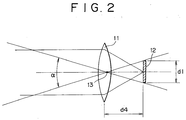
- the lens of the type described is formed, in principle, from a thin single convex lens 11 as shown in FIG. 2, and an image pickup element 12, which is a video image pickup device such as a CCD or a MOS or, in the case of a silver salt camera, a film, is disposed at the position of a focus of the convex lens 11.
- the NP point has been found by the inventor of the invention of the present application through a great number of experiments conducted in order to find out how a parallax which appears when a plurality of images are stitched can be reduced based on a basic idea of an optical system. Now, the NP point is described in connection with a case wherein light reflected from an object forms an image on an image pickup section 301 through an equivalent convex lens 300 as seen in FIG. 3.
- the equivalent convex lens 300 includes a plurality of lenses 302 to 308 arranged in order, and an aperture stop 309 is interposed between the lens 304 and the lens 305. From among a large number of principal rays which pass the center of the aperture stop 309, a principal ray 311 which passes a region nearest to the optical axis 310, that is, a Gauss region in which the aberration is smallest, is selected. A straight line component of the principal ray 311 in an object space 312 is extended, and a point at which the extension intersects with the optical axis 310 is set as an NP point (non-parallax point) 313.
- this is applied to a case wherein a plurality of cameras are used, that is, a case wherein a plurality of cameras are used to pick up an image in place of pivoting a single camera.
- the position of the NP point 13 is given only as a restricted point, and therefore, it is impossible to dispose a plurality of such cameras such that the NP points 13 of them may be a common NP point.
- the NP point is present in or around the lens, lens barrels, image pickup elements, signal processing circuit sections and other components of a plurality of cameras make a physical obstacle in that they make it difficult to set the NP points of the cameras so as to coincide with each other.
- the NP points 313 of all of the other cameras are positioned. This eliminates appearance of a parallax between images of different cameras.
- an imaginary NP point 313 can be set to the rear side of the lens barrel of each camera, that is, on the outside of each camera.
- the NP points 313 of all of the other cameras are positioned. Consequently, a common NP point region is obtained, and this can sufficiently reduce appearance of a parallax between images picked up by the cameras.
- the image pickup apparatus includes two video cameras each serving as image pickup means.
- the image pickup apparatus includes a first video camera 21 and a second video camera 25.
- the first video camera 21 includes a front lens 22 provided at a front position of a lens barrel not shown, a lens set 23 provided at a rear position of the lens barrel and including a plurality of lenses 23a to 23f, and a CCD 24 provided at a rearmost position of the lens barrel and serving as an image pickup element.
- the second video camera 25 similarly includes a front lens 26 provided at a front position of a lens barrel not shown, a lens set 27 provided at a rear position of the lens barrel and including a plurality of lenses 27a to 27f, and a CCD 28 provided at a rearmost position of the lens barrel and serving as an image pickup element.
- Each of the front lenses 22 and 26 is formed from a concave lens, and each of the lens sets 23 and 27 including the lenses 23a to 23f and 27a to 27f, respectively, is formed from a combination of concave and convex lenses.
- Each of the CCDs 24 and 28 has a flat plate-like configuration and is disposed on an optical axis P1 or P2 of the lenses 22 and 23 or 26 and 27 and secured to a rear end portion of the lens barrel.
- an aperture stop 29 is interposed between the lens 23b and the lens 23c.
- the aperture stop 29 selects, from among a large number of principal rays which pass the center of the aperture stop 29, that principal ray which passes a region nearest to the optical axis P1, that is, a Gauss region in which the aberration is smallest.
- a point at which an extension of a straight line component of the principal ray in an object space intersects with the optical axis P1 is set as a first NP point (non-parallax point) Q.
- an aperture stop 30 is interposed between the lens 27b and the lens 27c.
- the aperture stop 30 selects, from among a large number of principal rays which pass the center of the aperture stop 30, that principal ray which passes a region nearest to the optical axis P2, that is, a Gauss region in which the aberration is smallest.
- a point at which an extension of a straight line component of the principal ray in an object space intersects with the optical axis P2 is set as a second NP point Q1.
- the second NP point Q1 is set so as to be positioned within a region (spherical region) of a radius of 20 mm centered at the first NP point Q.
- ⁇ and ⁇ denote image pickup angles of view of the lenses of the video cameras 21 and 25, respectively, and a portion 31 indicated by slanting lines is an overlap region in which images picked up by the video cameras 21 and 25 overlap with each other.
- images of an image pickup object incoming to the lens barrels pass through the lenses 22 and 23 and the lenses 26 and 27 in the angles ⁇ and ⁇ of view as seen in FIG. 4 and inputted to the CCDs 24 and 28, respectively. Thereafter, the images are processed by processing sections and outputted to processing means, by which the images are stitched together while they are overlapped with each other at the overlapping portions 31 thereof.
- FIG. 5 shows an image pickup apparatus according to a second embodiment of the present invention.
- a pair of barrel holes are formed at opening angle positions of approximately 56 degrees at front end portions of a housing 40 having a substantially circular horizontal section and serving as a support member.
- Two lens barrels 41 and 42 are fitted in and secured to the barrel holes, and a plurality of lenses 43 or 44 are provided in each of the lens barrels 41 and 42.
- Another pair of barrel holes are perforated at rear end portions of the housing 40 on optical axes P1 and P2 of the lenses 43 and 44, and element barrels 45 and 46 are fitted in and secured to the barrel holes.
- CCDs 47 and 48 each serving as an image pickup element are secured to rear ends in the inside of the element barrels 45 and 46, respectively, and processing sections and processing means not shown are electrically connected to the CCDs 47 and 48.
- the lenses 43 and 44 are combined such that NP points Q and Q1 are set in the inside of the housing 40.
- the entire apparatus can be formed compact.
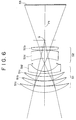
- FIG. 6 shows an image pickup apparatus according to a third embodiment of the present invention.
- a gap is provided between a plurality of lens sets 51 and 52, and the arrangement of lenses 51a, 51b, 51c and 51d of the front side lens set 51 and the arrangement of lenses 52a and 52b of the rear side lens set 52 are changed arbitrarily to set an NP point Q at a position rearwardly of the lens set 52 as seen in FIG. 6.
- reference numeral 53 in FIG. 6 denotes a CCD.
- a common NP point Q to a plurality of video cameras can be obtained by varying the positions of such NP points Q arbitrarily.
- a camera having a wide angle of view free from a parallax can be designed.
- FIG. 7 shows an image pickup apparatus according to a fourth embodiment of the present invention.
- the image pickup apparatus of the present embodiment allows image pickup over an overall circumference using four cameras disposed at angle positions spaced by approximately 90 degrees from each other in a circumferential direction.
- lens sets 75 to 78 provided in lens barrels 71 to 74 of the cameras include each a plurality of lenses 75a and 75b, 76a and 76b, 77a and 77b, or 78a and 78b and are set such that optical axes P1 to P4 thereof extend in tangential directions to positions of a central imaginary circle O spaced by 90 degrees from each other in a circumferential direction.
- the NP points Q1, Q2, Q3 and Q4 are set at mutually neighboring positions spaced by 90 degrees from each other in the circumferential direction of the imaginary circle 0.
- the NP points Q1, Q2, Q3 and Q4 do not occupy a common position but are positioned spaced a little from each other. Therefore, a parallax appears between each adjacent ones of the video cameras. However, since the displacement between the NP points Q1, Q2, Q3 and Q4 is small, the parallax can be suppressed sufficiently small.
- the image pickup apparatus can pick up an image over an overall circumference of an image pickup object, and the degree of freedom in arrangement is improved. Further, compact formation of the entire apparatus can be anticipated.
- cameras can be arranged not only two-dimensionally but also three-dimensionally including the upward and downward direction in which a plurality of cameras are disposed.
- the present invention further provides an image pickup apparatus, comprising a plurality of image pickup means for individually picking up images of a plurality of divisional image pickup objects of an image pickup object extending over a wide range, and processing means for receiving image information from the image pickup means and processing the image information to produce a single image by stitching images presented by the image information, the image pickup means being disposed such that, where a point at which an extension of a straight line component in an object space of a selected one of principal rays passing the center of an aperture stop for a lens set provided in each of the image pickup means which is positioned in a Gauss region intersects with an optical axis of the lens set is set as an NP point, the NP point is set to a position outside a lens barrel by disposing, intermediately of a light path which passes the lens set of the image pickup means, a mirror member for bending incoming light at a predetermined angle in an inclined relationship by a predetermined angle so that the incoming light is bent and besides the NP points of the image pickup
- the radius of the predetermined radius region is set to approximately 20 mm from the center which is one of the NP points.
- the inclination angle of the mirror is set arbitrarily with respect the optical axis of the lens set.
- the image pickup apparatus further comprises additional image pickup means having an NP point set within the predetermined radius region at a central position between the image pickup means and the mirror members which are arranged radially.
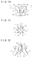
- FIG. 8 shows an image pickup apparatus according to a fifth embodiment of the present invention.
- four CCD cameras 111 of the same structure are used and arranged radially at positions spaced by 90 degrees from each other in a circumferential direction as viewed in plan as seen in FIG. 9. Further, the CCD cameras 111 are disposed such that the backs thereof oppose each other as seen in FIG. 10 so that they can image over a range of 360 degrees at a time.
- each of the CCD cameras 111 includes, as principal components thereof, a lens barrel 113 in which a plurality of lenses 112 (only one is shown) are successively disposed fixedly, a CCD 114 disposed in the inside of a rearmost end of the lens barrel 113 for scanning an electric signal, which increases in proportion to incoming light through the lenses 112, to successively extract such electric signals, and a processing section 115 provided at a rear end portion of the lens barrel 113 for processing image information from the CCD 114.
- the image pickup apparatus further includes processing means not shown for stitching images of the image signals from the processing section 115 to produce a single image.
- the lens barrel 113 includes a front end portion 113a extending horizontally and a rear end portion 113b extending vertically downwardly in a bent form from a rear end of the front end portion 113a.
- An outer end portion 113c of the bent portion of the lens barrel 113 is inclined at an angle of approximately 45 degrees with respect to an optical axis P of the lenses 112, and a mirror member 116 is secured to an inner face of the inclined outer end portion 113c.
- the mirror member 116 is disposed in an inclined relationship with the angle of approximately 45 degrees with respect to the optical axis P.
- the CCD 114 is in the form of a flat plate and is secured to an upper face of a bottom face portion 113d of the bent lens barrel 113.
- the processing section 115 is secured to a lower face of the rear end portion 113b of the lens barrel 113 and performs circuit processing of an AGC circuit and so forth for the image information signal from the CCD 114.
- the other three video cameras 111 are formed with the same configuration as that of the video camera 111 described above and the video cameras 111 are disposed such that the bent rear end portions 113b of the lens barrels 113 thereof are opposed to each other as seen in FIGS. 9 and 10 so that NP points Q thereof which are hereinafter described are disposed within a spherical region of a predetermined radius in a space among the rear end portions 113b and set at a substantially common position.
- one of the video cameras 111 includes an aperture stop not shown provided at a position forwardly of the lenses 112.
- the aperture stop selects, from among a large number of principal rays which pass the center of the aperture stop, that principal ray which passes a region very near to the optical axis P, that is, a Gauss region in which the aberration is very small.
- a point at which an extension of a straight line component of the principal ray in an object space intersects with the optical axis P is set as a first NP point (non-parallax point) Q.
- any other one of the video cameras 111 includes an aperture stop not shown provided at a position forwardly of the lenses 112.
- the aperture stop selects, from among a large number of principal rays which pass the center of the aperture stop, that principal ray which passes a region very near to the optical axis P, that is, a Gauss region in which the aberration is very small.
- a point at which an extension of a straight line component of the principal ray in an object space intersects with the optical axis P is set as a second NP point Q.
- Incoming light passing through each of the lenses 112 is bent downwardly by the mirror member 116, and consequently, the NP point Q1 thereof is positioned within the bent rear end portion 113b of the lens barrel 113.
- the NP point Q should be formed at a position rearwardly of the outer end portion 113c as indicated by an alternate long and short dash line in FIG. 8.
- the region of a radius of 20 mm on the rear side of the four video cameras 111 can be set as a common imaginary NP point Q.
- the video cameras 111 are set such that the NP points thereof may be disposed within a region (spherical region) of a predetermined radius.
- the video cameras 111 are set such that the NP points thereof may be disposed within a region (spherical region) of a radius of approximately 20 mm as described hereinabove.
- an image of an image pickup object incoming to the lens barrel 113 passes through the lenses 112 and comes to the mirror member 116, and is then bent downwardly at an angle of approximately 90 degrees by the mirror member 116 and then inputted to the CCD 114 as seen in FIG. 8. Thereafter, the image is processed by the processing section 115 and outputted to the processing means.
- the processing means stitches such four images received from the video cameras 111 to each other such that they overlap with each other at overlapping portions therebetween.
- the NP points are disposed collectively in the region of the radius of substantially 20 mm, appearance of a parallax phenomenon by the video cameras 111 is prevented and the images can be stitched to each other well, and high precision image processing can be achieved.
- the projecting value of each of the NP points Q to the outer side from the lens barrels 113 can be set higher as the angle of view decreases.
- the NP point Q can be set at the central position of the entire apparatus and can be disposed at a further rearwardly receding position.
- FIG. 12 shows an image pickup apparatus according to a seventh embodiment of the present invention.
- the NP points Q of the video cameras 111 disposed radially are set so as to coincide substantially with each other, and also the NP point of the video camera 121 is set so as to coincide substantially with the NP points Q of the video cameras 111.
- the image pickup apparatus of the present embodiment includes a first image pickup section including a plurality of image pickup means, that is, a camera set (two video cameras 111) for reflecting and bending incoming light and picking up an image of the incoming light and a second image pickup section (additional image pickup means) including a camera set (video camera 121) for picking up an image of incoming light directly without reflecting the incoming light, NP points Q of the image pickup means of the first and second image pickup sections being made substantially coincide with each other.
- a first image pickup section including a plurality of image pickup means, that is, a camera set (two video cameras 111) for reflecting and bending incoming light and picking up an image of the incoming light
- a second image pickup section additional image pickup means
- NP points Q of the image pickup means of the first and second image pickup sections being made substantially coincide with each other.
- the NP points Q of the video cameras 111 and 112 can be set to a rearward central position of the entire apparatus, and an image pickup object can be imaged over a predetermined angle of view by the central video camera 121 and the image pickup angle can be further increased by the video cameras 111 and 121.
- FIG. 13 shows an image pickup apparatus according to an eighth embodiment of the present invention.
- the inclination angle ⁇ of the mirror member 116 from the optical axis P is set to an angle other than 45 degrees such as, for example, 30 degrees or 42 degrees. This increases the degree of freedom of the layout of the image pickup element 114 and further increases the degree of freedom in arrangement of video cameras.
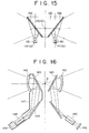
- FIGS. 14 and 15 show an image pickup apparatus according a ninth embodiment of the present invention.
- mirrors 132 are secured to flat face portions of an octagonal pyramid-shaped support member 130 and disposed such that incoming light (indicated by an arrow mark) is first reflected by the mirrors 132 and then introduced into a plurality of lenses of each of eight video cameras 131 provided corresponding to the mirrors 132.
- reference numeral 141 denotes the NP point Q of the lenses of each of the video cameras 131.
- imaginary NP points 140 can be made coincide with each other in the support member 130 for the eight video cameras 131.
- FIGS. 16 and 17 show an image pickup apparatus according to a tenth embodiment of the present invention.
- eight cameras 147 are disposed radially such that imaginary NP points Q are set to a substantially central position of eight first mirrors 143 disposed forwardly of the cameras 147 and arranged in a substantially pyramid-like configuration.
- first mirrors 143 are positioned between imaginary NP points Q and nearest objective lenses 142 of the image pickup lenses such that the imaginary NP points Q of the cameras 147 may substantially coincide with each other.
- a second mirror 144 is disposed between a rear lens set 145 and a first mirror 143 such that a light path is bent thereby to assure a space around each image pickup element (CCD or the like) 146. This makes it possible to form the apparatus from 3CCD cameras of a high picture quality.
- FIGS. 18 and 19 show an image pickup apparatus according to an eleventh embodiment of the present invention.
- the image pickup apparatus of the present embodiment is a modification to the image pickup apparatus according to the ninth embodiment described hereinabove with reference to FIGS. 14 and 15 but is different in that, at a central position of a plurality of video cameras disposed radially, another video camera 201 having a vertical lens barrel is disposed similarly as in the image pickup apparatus of the seventh embodiment described hereinabove with reference to FIG. 12.
- FIGS. 18 and 19 eight mirrors 132 are secured to flat face portions of an octagonal pyramid-shaped support member 130 and disposed such that incoming light (indicated by an arrow mark) is first reflected by the mirrors 132 and then introduced into a plurality of lenses of each of eight video cameras 131 provided corresponding to the mirrors 132.
- reference numeral 141 denotes the NP point Q of the lenses of each of the video cameras 131.
- imaginary NP points 140 can be made coincide with each other in the support member 130 for the eight video cameras 131.
- a single lens (not shown) and a video camera 201 for imaging upwardly are disposed at a central portion of a hollow of the support member 130.
- the video camera 201 directly picks up an image of incident light which is not reflected by the mirrors 132.
- the NP point of the video camera 201 is made substantially coincide with the imaginary NP points 140 described above.
- the image pickup apparatus of the present embodiment includes a first image pickup section including a plurality of image pickup means, that is, a camera set (eight video cameras 131) for reflecting and bending incoming light by means of the mirrors 132 and picking up an image of the incoming light and a second image pickup section (additional image pickup means) including a camera (video camera 201) for picking up an image of incoming light directly without reflecting the incoming light by means of the mirrors 132, NP points Q of the image pickup means of the first and second image pickup sections being made substantially coincide with each other.
- a first image pickup section including a plurality of image pickup means, that is, a camera set (eight video cameras 131) for reflecting and bending incoming light by means of the mirrors 132 and picking up an image of the incoming light
- a second image pickup section additional image pickup means
- NP points Q of the image pickup means of the first and second image pickup sections being made substantially coincide with each other.
- an image pickup object can be imaged over a predetermined angle of view by the central video camera 201 and the image pickup angle can be further increased by the video cameras 131 and 201.
- the imaginary NP points 140 of the camera group wherein the mirrors 132 are disposed in front of the lenses to bend the light paths to pick up images that is, the eight video cameras 131
- the NP point of the camera group wherein incoming light is imaged directly without being reflected by any mirror 132, that is, the central video camera 201 are made substantially coincide with each other, appearance of a parallax can be prevented sufficiently and omnidirectional images other than a downward image can be picked up.
- mirror members need not necessarily be disposed in an octagonal pyramid-like configuration but may be disposed in any polygonal pyramid-line configuration.
- a plurality of plane mirrors are disposed in a polygonal pyramid-like configuration as the mirror members of the first image pickup section, and the second image pickup section is disposed on the center line of the polygonal pyramid, that is, on a normal line to the polygonal pyramid, such that the optical axes thereof may substantially coincide with each other and the NP points thereof may substantially coincide with each other.
- FIGS. 20 and 21 show an image pickup apparatus according to a twelfth embodiment of the present invention.
- the image pickup apparatus of the present embodiment is a modification to the image pickup apparatus of the tenth embodiment described hereinabove with reference to FIGS. 16 and 17 but is different in that, at a central position of a plurality of video cameras disposed radially, another video camera 202 having a vertical lens barrel is disposed similarly as in the image pickup apparatus of the seventh embodiment described hereinabove with reference to FIG. 12.
- eight video cameras 147 are disposed radially such that imaginary NP points Q are set to a substantially central position of eight first mirrors 143 disposed at positions forwardly of the video cameras 147 and arranged in a substantially pyramid-like configuration.
- first mirrors 143 are positioned between imaginary NP points Q and nearest objective lenses 142 of the image pickup lenses such that the imaginary NP points Q of the cameras 147 may substantially coincide with each other.
- a second mirror 144 is disposed between a rear lens set 145 and a first mirror 143 such that a light path is bent thereby to assure a space around each image pickup element (CCD or the like) 146. This makes it possible to form the apparatus from 3CCD cameras of a high picture quality.
- a single video camera 202 for imaging upwardly are disposed at a central position among the first mirrors 143 disposed radially.
- the video camera 202 directly picks up an image of incident light which is not reflected by the first mirrors 143.
- the NP point of the video camera 202 is made substantially coincide with the imaginary NP points Q described above.
- the image pickup apparatus of the present embodiment includes a first image pickup section including a plurality of image pickup means, that is, a camera set (eight video cameras 147) for reflecting and bending incoming light by means of the first mirror 143s and picking up an image of the incoming light and a second image pickup section (additional image pickup means) including a camera set (video camera 202) for picking up an image of incoming light directly without reflecting the incoming light, NP points of the image pickup means of the first and second image pickup sections being made substantially coincide with each other.
- a first image pickup section including a plurality of image pickup means, that is, a camera set (eight video cameras 147) for reflecting and bending incoming light by means of the first mirror 143s and picking up an image of the incoming light
- a second image pickup section additional image pickup means
- NP points of the image pickup means of the first and second image pickup sections being made substantially coincide with each other.
- an image pickup object can be imaged over a predetermined angle of view by the central video camera 202 and the image pickup angle can be further increased by the video cameras 147 and 202.
- an image pickup apparatus which includes a color separation prism and a 3CCD camera for a high picture quality in which a signal processing circuit occupies a great part can image over a wide range.
- a mirror member for bending incoming light at a predetermined angle may be placed in an inclined relationship by a predetermined angle at one or more of locations of a light path passing a lens of image pickup means between an image pickup object and one of lenses nearest to the image pickup object (in the object space), between the lens nearest to the image pickup object and another one of the lenses which is nearest to an image and between the lens nearest to the image and the plane of the image (image space).
- the present invention is not limited to the embodiments described above but may have various configurations within the spirit and scope thereof. For example, it is possible to vary the arrangement of video cameras or lens barrels or increase or decrease the number of them to effect three-dimensional and efficient image pickup.
Landscapes
- Engineering & Computer Science (AREA)
- Multimedia (AREA)
- Signal Processing (AREA)
- Studio Devices (AREA)
- Stereoscopic And Panoramic Photography (AREA)
Applications Claiming Priority (6)
| Application Number | Priority Date | Filing Date | Title |
|---|---|---|---|
| JP2001030700 | 2001-02-07 | ||
| JP2001030700 | 2001-02-07 | ||
| JP2001034846 | 2001-02-13 | ||
| JP2001034846 | 2001-02-13 | ||
| JP2001301835 | 2001-09-28 | ||
| JP2001301835A JP2002320124A (ja) | 2001-02-13 | 2001-09-28 | 撮像装置 |
Publications (2)
| Publication Number | Publication Date |
|---|---|
| EP1231780A2 true EP1231780A2 (de) | 2002-08-14 |
| EP1231780A3 EP1231780A3 (de) | 2004-01-14 |
Family
ID=27345928
Family Applications (1)
| Application Number | Title | Priority Date | Filing Date |
|---|---|---|---|
| EP02002647A Ceased EP1231780A3 (de) | 2001-02-07 | 2002-02-05 | Bildaufnahmevorrichtung |
Country Status (2)
| Country | Link |
|---|---|
| US (1) | US7006123B2 (de) |
| EP (1) | EP1231780A3 (de) |
Cited By (7)
| Publication number | Priority date | Publication date | Assignee | Title |
|---|---|---|---|---|
| EP1916838A1 (de) * | 2006-10-26 | 2008-04-30 | Fluke Corporation | Integriertes multiples Bildgebungssystem |
| WO2012032236A1 (fr) * | 2010-09-09 | 2012-03-15 | Giroptic | Dispositif optique pour la capture d'images selon un champ de 360 ° |
| EP2619987A4 (de) * | 2010-09-24 | 2014-08-27 | Microsoft Corp | Bildgebungssystem mit aktiver beleuchtung und weitwinkelsichtfeld |
| FR3011645A1 (fr) * | 2013-10-07 | 2015-04-10 | Giroptic | Dispositif optique pour la capture d'images selon un champ de vision horizontal de 360° |
| EP3190461A1 (de) * | 2016-01-05 | 2017-07-12 | Giroptic | Zweilinsen optische anordnung |
| US9797980B2 (en) | 2002-09-20 | 2017-10-24 | Visual Intelligence Lp | Self-calibrated, remote imaging and data processing system |
| USRE49105E1 (en) | 2002-09-20 | 2022-06-14 | Vi Technologies, Llc | Self-calibrated, remote imaging and data processing system |
Families Citing this family (29)
| Publication number | Priority date | Publication date | Assignee | Title |
|---|---|---|---|---|
| JP2003066303A (ja) * | 2001-08-28 | 2003-03-05 | Sony Corp | 撮像装置 |
| AU2003226047A1 (en) * | 2002-04-10 | 2003-10-27 | Pan-X Imaging, Inc. | A digital imaging system |
| JP2006030664A (ja) * | 2004-07-16 | 2006-02-02 | Sony Corp | 撮像装置 |
| JP4345829B2 (ja) * | 2007-03-09 | 2009-10-14 | ソニー株式会社 | 画像表示システム、画像表示装置、画像表示方法およびプログラム |
| TWI383666B (zh) * | 2007-08-21 | 2013-01-21 | Sony Taiwan Ltd | 多重鏡頭相機系統之先進式動態接圖方法 |
| US9485495B2 (en) | 2010-08-09 | 2016-11-01 | Qualcomm Incorporated | Autofocus for stereo images |
| JP6142467B2 (ja) * | 2011-08-31 | 2017-06-07 | 株式会社リコー | 撮像光学系および全天球型撮像装置および撮像システム |
| US9438889B2 (en) | 2011-09-21 | 2016-09-06 | Qualcomm Incorporated | System and method for improving methods of manufacturing stereoscopic image sensors |
| BR112014024941A2 (pt) | 2012-04-05 | 2017-09-19 | Magic Leap Inc | dispositivo de imagem de campo de visão amplo com capacidade de focalização ativa |
| US9398264B2 (en) | 2012-10-19 | 2016-07-19 | Qualcomm Incorporated | Multi-camera system using folded optics |
| US9503638B1 (en) | 2013-02-04 | 2016-11-22 | UtopiaCompression Corporation | High-resolution single-viewpoint panoramic camera and method of obtaining high-resolution panoramic images with a single viewpoint |
| US10178373B2 (en) | 2013-08-16 | 2019-01-08 | Qualcomm Incorporated | Stereo yaw correction using autofocus feedback |
| US9374516B2 (en) | 2014-04-04 | 2016-06-21 | Qualcomm Incorporated | Auto-focus in low-profile folded optics multi-camera system |
| US9383550B2 (en) | 2014-04-04 | 2016-07-05 | Qualcomm Incorporated | Auto-focus in low-profile folded optics multi-camera system |
| CN111510621B (zh) | 2014-05-06 | 2021-11-12 | 扎卡里亚·尼亚齐 | 成像系统 |
| US10013764B2 (en) | 2014-06-19 | 2018-07-03 | Qualcomm Incorporated | Local adaptive histogram equalization |
| US9541740B2 (en) | 2014-06-20 | 2017-01-10 | Qualcomm Incorporated | Folded optic array camera using refractive prisms |
| US9819863B2 (en) | 2014-06-20 | 2017-11-14 | Qualcomm Incorporated | Wide field of view array camera for hemispheric and spherical imaging |
| US9386222B2 (en) | 2014-06-20 | 2016-07-05 | Qualcomm Incorporated | Multi-camera system using folded optics free from parallax artifacts |
| US9549107B2 (en) | 2014-06-20 | 2017-01-17 | Qualcomm Incorporated | Autofocus for folded optic array cameras |
| US9294672B2 (en) | 2014-06-20 | 2016-03-22 | Qualcomm Incorporated | Multi-camera system using folded optics free from parallax and tilt artifacts |
| US9832381B2 (en) | 2014-10-31 | 2017-11-28 | Qualcomm Incorporated | Optical image stabilization for thin cameras |
| US10326981B2 (en) * | 2015-05-15 | 2019-06-18 | Semyon Nisenzon | Generating 3D images using multi-resolution camera set |
| CA3029748A1 (en) * | 2016-07-05 | 2018-01-11 | Zero Parallax Technologies Ab | Spherical camera lens system, camera system and lens assembly |
| JP7467958B2 (ja) * | 2019-02-13 | 2024-04-16 | 株式会社リコー | 撮像装置 |
| CN110519529B (zh) * | 2019-05-14 | 2021-08-06 | 南开大学 | 一种基于光学拼接的同视点环视成像系统及成像方法 |
| WO2020263865A1 (en) | 2019-06-24 | 2020-12-30 | Circle Optics, Inc. | Opto-mechanics of panoramic capture devices with abutting cameras |
| CN110764338B (zh) * | 2019-10-30 | 2022-02-15 | 长光卫星技术有限公司 | 一种具备调焦功能的轻型空间相机主承力装置 |
| US12332549B2 (en) | 2019-12-23 | 2025-06-17 | Circle Optics, Inc. | Mounting systems for multi-camera imagers |
Family Cites Families (12)
| Publication number | Priority date | Publication date | Assignee | Title |
|---|---|---|---|---|
| JP3523667B2 (ja) * | 1993-08-24 | 2004-04-26 | オリンパス株式会社 | 複眼式光学系 |
| JPH08194170A (ja) * | 1995-01-13 | 1996-07-30 | Olympus Optical Co Ltd | 立体視内視鏡 |
| US6141034A (en) * | 1995-12-15 | 2000-10-31 | Immersive Media Co. | Immersive imaging method and apparatus |
| JP4086914B2 (ja) * | 1996-06-13 | 2008-05-14 | ペンタックス株式会社 | カメラバック交換式カメラ |
| US6549650B1 (en) * | 1996-09-11 | 2003-04-15 | Canon Kabushiki Kaisha | Processing of image obtained by multi-eye camera |
| US5937212A (en) * | 1996-11-15 | 1999-08-10 | Canon Kabushiki Kaisha | Image pickup apparatus |
| JPH1146317A (ja) * | 1997-07-28 | 1999-02-16 | Sony Corp | ビデオカメラ |
| JP2001204015A (ja) * | 2000-01-18 | 2001-07-27 | Sony Corp | 周囲カメラ・システム、周囲カメラの撮像画像に基づいて周囲画像を生成する方法、隣接カメラによる撮像画像の接続処理装置及び方法、並びに、隣接カメラを用いた距離測定装置及び方法 |
| JP2002229137A (ja) * | 2001-02-06 | 2002-08-14 | Sony Corp | 撮像装置 |
| JP2002229139A (ja) * | 2001-02-06 | 2002-08-14 | Sony Corp | 撮像装置 |
| EP1427191A4 (de) * | 2001-08-17 | 2006-08-16 | Sony Corp | Abbildungseinrichtung |
| JP2003066303A (ja) * | 2001-08-28 | 2003-03-05 | Sony Corp | 撮像装置 |
-
2002
- 2002-02-05 EP EP02002647A patent/EP1231780A3/de not_active Ceased
- 2002-02-06 US US10/072,223 patent/US7006123B2/en not_active Expired - Fee Related
Cited By (11)
| Publication number | Priority date | Publication date | Assignee | Title |
|---|---|---|---|---|
| US9797980B2 (en) | 2002-09-20 | 2017-10-24 | Visual Intelligence Lp | Self-calibrated, remote imaging and data processing system |
| USRE49105E1 (en) | 2002-09-20 | 2022-06-14 | Vi Technologies, Llc | Self-calibrated, remote imaging and data processing system |
| EP1916838A1 (de) * | 2006-10-26 | 2008-04-30 | Fluke Corporation | Integriertes multiples Bildgebungssystem |
| WO2012032236A1 (fr) * | 2010-09-09 | 2012-03-15 | Giroptic | Dispositif optique pour la capture d'images selon un champ de 360 ° |
| FR2964757A1 (fr) * | 2010-09-09 | 2012-03-16 | Giroptic | Dispositif optique pour la capture d'images selon un champ de 360° |
| EP2619987A4 (de) * | 2010-09-24 | 2014-08-27 | Microsoft Corp | Bildgebungssystem mit aktiver beleuchtung und weitwinkelsichtfeld |
| US8988508B2 (en) | 2010-09-24 | 2015-03-24 | Microsoft Technology Licensing, Llc. | Wide angle field of view active illumination imaging system |
| FR3011645A1 (fr) * | 2013-10-07 | 2015-04-10 | Giroptic | Dispositif optique pour la capture d'images selon un champ de vision horizontal de 360° |
| WO2015052410A1 (fr) * | 2013-10-07 | 2015-04-16 | Giroptic | Dispositif optique pour la capture d'images selon un champ de vision horizontal de 360° |
| EP3190461A1 (de) * | 2016-01-05 | 2017-07-12 | Giroptic | Zweilinsen optische anordnung |
| WO2017118665A1 (en) * | 2016-01-05 | 2017-07-13 | Giroptic | Two-lens optical arrangement |
Also Published As
| Publication number | Publication date |
|---|---|
| US20040201769A1 (en) | 2004-10-14 |
| EP1231780A3 (de) | 2004-01-14 |
| US7006123B2 (en) | 2006-02-28 |
Similar Documents
| Publication | Publication Date | Title |
|---|---|---|
| EP1231780A2 (de) | Bildaufnahmevorrichtung | |
| US7649690B2 (en) | Integrated panoramic and forward optical device, system and method for omnidirectional signal processing | |
| RU2201607C2 (ru) | Всенаправленное устройство формирования изображения | |
| US7126756B2 (en) | Image pickup device | |
| US8305425B2 (en) | Solid-state panoramic image capture apparatus | |
| JP3549898B2 (ja) | 広角の画像形成用システム及び方法 | |
| RU2000117577A (ru) | Всенаправленное устройство формирования изображения | |
| US20170027427A1 (en) | Radial Scanner Imaging System | |
| JP2003143459A (ja) | 複眼撮像系およびこれを備えた装置 | |
| US20050117227A1 (en) | Panoramic imaging system with optical zoom capability | |
| JP4051945B2 (ja) | 撮像装置 | |
| JP2002320124A (ja) | 撮像装置 | |
| CN100481885C (zh) | 成像装置 | |
| JPH09139878A (ja) | 画像処理システム | |
| JP2003162018A (ja) | 撮像装置 | |
| JP2000322564A (ja) | 全方位視覚センサ | |
| WO2006009088A1 (ja) | 撮像装置 | |
| JPH10107975A (ja) | 画像入力装置 | |
| JP3888847B2 (ja) | 広視野映像撮像装置 | |
| JP2002229138A (ja) | 撮像装置 | |
| US20110115916A1 (en) | System for mosaic image acquisition | |
| JP2004070002A (ja) | 撮像装置 | |
| WO2025053093A1 (ja) | 全周カメラ | |
| CN110737078A (zh) | 一种用于全方位图像采集复合镜头的双焦距摄像镜头 | |
| WO2002077707A1 (en) | A device and a arrangement method of sector lens for panorama image |
Legal Events
| Date | Code | Title | Description |
|---|---|---|---|
| PUAI | Public reference made under article 153(3) epc to a published international application that has entered the european phase |
Free format text: ORIGINAL CODE: 0009012 |
|
| AK | Designated contracting states |
Kind code of ref document: A2 Designated state(s): AT BE CH CY DE DK ES FI FR GB GR IE IT LI LU MC NL PT SE TR |
|
| AX | Request for extension of the european patent |
Free format text: AL;LT;LV;MK;RO;SI |
|
| PUAL | Search report despatched |
Free format text: ORIGINAL CODE: 0009013 |
|
| AK | Designated contracting states |
Kind code of ref document: A3 Designated state(s): AT BE CH CY DE DK ES FI FR GB GR IE IT LI LU MC NL PT SE TR |
|
| AX | Request for extension of the european patent |
Extension state: AL LT LV MK RO SI |
|
| 17P | Request for examination filed |
Effective date: 20040517 |
|
| AKX | Designation fees paid |
Designated state(s): DE FR GB |
|
| STAA | Information on the status of an ep patent application or granted ep patent |
Free format text: STATUS: THE APPLICATION HAS BEEN REFUSED |
|
| 18R | Application refused |
Effective date: 20111103 |