EP1232810A1 - Biegepresse und verfahren zum steuern einer bidirektionalen flüssigkeitspumpe eines hydraulikzylinders einer biegepresse - Google Patents
Biegepresse und verfahren zum steuern einer bidirektionalen flüssigkeitspumpe eines hydraulikzylinders einer biegepresse Download PDFInfo
- Publication number
- EP1232810A1 EP1232810A1 EP00971751A EP00971751A EP1232810A1 EP 1232810 A1 EP1232810 A1 EP 1232810A1 EP 00971751 A EP00971751 A EP 00971751A EP 00971751 A EP00971751 A EP 00971751A EP 1232810 A1 EP1232810 A1 EP 1232810A1
- Authority
- EP
- European Patent Office
- Prior art keywords
- ram
- moving speed
- fluid pump
- pressure
- bidirectional fluid
- Prior art date
- Legal status (The legal status is an assumption and is not a legal conclusion. Google has not performed a legal analysis and makes no representation as to the accuracy of the status listed.)
- Granted
Links
Images



Classifications
-
- B—PERFORMING OPERATIONS; TRANSPORTING
- B21—MECHANICAL METAL-WORKING WITHOUT ESSENTIALLY REMOVING MATERIAL; PUNCHING METAL
- B21D—WORKING OR PROCESSING OF SHEET METAL OR METAL TUBES, RODS OR PROFILES WITHOUT ESSENTIALLY REMOVING MATERIAL; PUNCHING METAL
- B21D5/00—Bending sheet metal along straight lines, e.g. to form simple curves
- B21D5/02—Bending sheet metal along straight lines, e.g. to form simple curves on press brakes without making use of clamping means
-
- B—PERFORMING OPERATIONS; TRANSPORTING
- B30—PRESSES
- B30B—PRESSES IN GENERAL
- B30B15/00—Details of, or accessories for, presses; Auxiliary measures in connection with pressing
- B30B15/16—Control arrangements for fluid-driven presses
-
- F—MECHANICAL ENGINEERING; LIGHTING; HEATING; WEAPONS; BLASTING
- F15—FLUID-PRESSURE ACTUATORS; HYDRAULICS OR PNEUMATICS IN GENERAL
- F15B—SYSTEMS ACTING BY MEANS OF FLUIDS IN GENERAL; FLUID-PRESSURE ACTUATORS, e.g. SERVOMOTORS; DETAILS OF FLUID-PRESSURE SYSTEMS, NOT OTHERWISE PROVIDED FOR
- F15B15/00—Fluid-actuated devices for displacing a member from one position to another; Gearing associated therewith
- F15B15/20—Other details, e.g. assembly with regulating devices
- F15B15/28—Means for indicating the position, e.g. end of stroke
- F15B15/2815—Position sensing, i.e. means for continuous measurement of position, e.g. LVDT
- F15B15/2838—Position sensing, i.e. means for continuous measurement of position, e.g. LVDT with out using position sensors, e.g. by volume flow measurement or pump speed
-
- F—MECHANICAL ENGINEERING; LIGHTING; HEATING; WEAPONS; BLASTING
- F15—FLUID-PRESSURE ACTUATORS; HYDRAULICS OR PNEUMATICS IN GENERAL
- F15B—SYSTEMS ACTING BY MEANS OF FLUIDS IN GENERAL; FLUID-PRESSURE ACTUATORS, e.g. SERVOMOTORS; DETAILS OF FLUID-PRESSURE SYSTEMS, NOT OTHERWISE PROVIDED FOR
- F15B2211/00—Circuits for servomotor systems
- F15B2211/80—Other types of control related to particular problems or conditions
- F15B2211/85—Control during special operating conditions
- F15B2211/851—Control during special operating conditions during starting
Definitions
- the present invention relates to a press brake which executes a bending process by vertically moving a ram by means of a hydraulic cylinder, and a method of controlling a bidirectional fluid pump of a hydraulic cylinder of the press brake.
- pipings 101 and 103 connected to an upper cylinder chamber or a lower cylinder chamber of a hydraulic cylinder are connected to a bidirectional fluid pump 107 rotated by a servo motor 105. Further, the pipings 101 and 103 are respectively connected to an oil tank 113 via check valves 109 and 111.
- the bidirectional fluid pump 107 is rotated by the servo motor 105, a working fluid is supplied to the upper or lower cylinder chamber (not shown) through the piping 101 or the piping 103, and a ram is vertically moved. At this time, the working fluid is supplied from the oil tank 113 via the check valve 109 or the check valve 111.
- a command is given to the servo motor 105 so that the ram is vertically moved according to a pattern shown in Fig. 2, thereby rotating the bidirectional fluid pump 107. That is, the ram increases a speed according to a fixed acceleration, moves at a fixed speed after reaching a predetermined speed, and reduces the speed according to a fixed speed reduction rate.
- This invention is made by taking the problems in the prior art mentioned above into consideration.
- an object of this invention is to provide a press brake and a method of controlling a bidirectional fluid pump of a hydraulic cylinder of the press brake which can increase a motion gain of a ram so as to improve a productivity by reducing a shock at a time of reverse rotation.
- Another object of this invention is to provide a press brake and a method of controlling a bidirectional fluid pump of a hydraulic cylinder of the press brake which can reduce a noise generated by the bidirectional fluid pump operating the hydraulic cylinder.
- a press brake comprising: a ram capable of moving upward and downward; a hydraulic cylinder moving the ram upward and downward; a bidirectional fluid pump operating the hydraulic cylinder in a vertical direction, the bidirectional fluid pump being connected to the hydraulic cylinder and rotating forward and backward so as to move the ram upward and downward; a servo motor rotating the bidirectional fluid pump; a ram position detecting means for detecting a position of the ram in a vertical direction; and a control apparatus controlling the servo motor, wherein the control apparatus further comprises: a ram moving speed pattern command portion instructing a preset ram moving speed pattern of setting a warming-up time or distance for temporarily keeping a ram speed after reversing a rotation of the bidirectional fluid pump so as to reverse a vertical movement of the ram to a predetermined time or a predetermined distance, and thereafter changing the ram speed to a predetermined speed; a command position counter reading a
- the control apparatus controls the servo motor so as to reverse the rotation of the bidirectional fluid pump.
- the ram moving speed pattern command portion of the control apparatus executes the pattern command of the preset ram moving speed pattern of keeping the moving speed of the ram fixed for the predetermined warming-up time or the predetermined distance and thereafter changing the moving speed of the ram to the predetermined speed, after the reverse rotation.
- the command position counter reads the ram position from the ram moving speed pattern, and the adder adds the read value and an actual ram position detected by the ram position detector, whereby the rotation of the servo motor is controlled so that the ram is positioned at a desired position.
- a method of controlling a bidirectional fluid pump of a hydraulic cylinder of a press brake comprising the steps of: reversing a bidirectional fluid pump so as to reverse a vertical movement of the ram; after the step, setting a warming-up time or a warming-up distance to a predetermined time or a predetermined distance for temporarily keeping a moving speed of the ram fixed; after the step, controlling bidirectional fluid pump so as to change the ram speed to a predetermined speed; and due to the structure, executing a bending process in accordance that the hydraulic cylinder is moved upward and downward in correspondence to the rotational direction of the bidirectional fluid pump and the ram is moved upward and downward.
- the vertical movement of the ram is executed by keeping the moving speed of the ram fixed for the predetermined warming-up time or the predetermined distance and thereafter changing the moving speed of the ram to the predetermined speed, after the reverse rotation.
- a method of controlling a bidirectional fluid pump of a hydraulic cylinder of a press brake comprising the steps of: measuring a hydraulic force in a bidirectional fluid pump and computing a change amount of the hydraulic force; calculating a ram moving speed with respect to a pressure detected at a certain time or a ram moving speed with respect to a change amount of the pressure at this time, on the basis of a predetermined pressure-ram moving speed relation or a pressure change amount-ram moving speed relation in order to reduce a noise at a time that the bidirectional fluid pump rotates; determining and instructing a rotational number of the servo motor to a rotational number of a ram moving speed with respect to the pressure, in order to compare the ram moving speed with respect to the pressure with a ram moving speed with respect to the change amount of pressure so as to obtain a ram moving speed having a lower speed; and operating the bidirectional fluid pump so as to rotate the servo motor, andmoving the ram upward and
- a method of controlling a bidirectional fluid pump of a hydraulic cylinder of a press brake comprising the steps of: measuring a hydraulic force in a bidirectional fluid pump and computing a change amount of the hydraulic force; calculating a ram moving speed with respect to a pressure detected at a certain time and a ram moving speed with respect to a change amount of the pressure at this time, on the basis of a predetermined pressure-ram moving speed relation or a pressure change amount-ram moving speed relation in order to reduce a noise at a time that the bidirectional fluid pump rotates; determining and instructing a rotational number of the servo motor to a rotational number of a ram moving speed with respect to the pressure, in order to compare the ram moving speed with respect to the pressure with a ram moving speed with respect to the change amount of pressure so as to obtain a ram moving speed having a lower speed; and operating the bidirectional fluid pump so as to rotate the servo motor, andmoving the ram upward and
- the control is executed by detecting the hydraulic force of the bidirectional fluid pump rotated by the servo motor and operating the hydraulic cylinder and calculating the change amount of the hydraulic force, selecting the lower ram moving speed in order to reduce the noise at the optional time on the basis of the predetermined pressure-ram moving speed relation and pressure change amount-ram moving speed relation in order to reduce the noise at a time when the bidirectional fluid pump rotates, and instructing the rotational number corresponding to the selected ram moving speed to the servo motor.
- a press brake comprising: a ram capable of moving upward and downward; a hydraulic cylinder moving the ram upward and downward; a bidirectional fluid pump operating the hydraulic cylinder in a vertical direction, the bidirectional fluid pump being connected to the hydraulic cylinder and rotating forward and backward so as to move the ram upward and downward; a servo motor rotating the bidirectional fluid pump; a ram position detecting means for detecting a position of the ram in a vertical direction; a rammoving speed pattern command portion instructing a moving pattern of the ram; a computing portion computing a pressure sensor or a pressure change amount; a ram moving speed computing portion computing a ram moving speed for preventing a noise, on the basis of a detected pressure from the pressure sensor or a pressure change amount from the computing portion computing the pressure change amount; and a servo motor rotation command portion instructing a rotational number corresponding to the ram moving speed to the servo motor.
- a press brake comprising: a ram capable of moving upward and downward; a hydraulic cylinder moving the ram upward and downward; a bidirectional fluid pump operating the hydraulic cylinder in a vertical direction, the bidirectional fluid pump being connected to the hydraulic cylinder and rotating forward and backward so as to move the ram upward and downward; a servo motor rotating the bidirectional fluid pump; a ram position detecting means for detecting a position of the ram in a vertical direction; a ram moving speed pattern command portion instructing a moving pattern of the ram; a ram position detecting means for detecting the ram position; an adder applying a rotation command to the servo motor rotating the bidirectional fluid pump for the purpose of comparing an instructed ram position from the ram moving speed pattern command portion with an actual ram position from the ram position detecting means so as to correct the ram position; a pressure sensor detecting a pressure of the bidirectional fluid pump; a computing portion computing a pressure change amount on the basis
- the bending process having a high accuracy is executed by controlling the servo motor according to the command pattern from the ram moving speed pattern command portion so as to move the hydraulic cylinder upward and downward by the bidirectional fluid pump, detecting the actual ram position by the ram position detecting means, and comparing the instructed position with the actual ram position by the adder so as to control the servo motor, however, at this time, the hydraulic force of the bidirectional fluid pump is detected by the pressure sensor provided in the bidirectional fluid pump, the computing portion calculates the change amount of the hydraulic force on the basis of the pressure, the ram speed determining portion selects the lower ram moving speed and determines the ram moving speed in order to reduce the noise at the optional time, on the basis of the pressure-ram moving speed relation and the pressure change amount-ram moving speed relation which are previously determined and stored in the memory so as to reduce the noise at a time when the bidirectional fluid pump rotates, and the servo motor rotational number command portion instructs the rotational number corresponding to the selected ram moving
- FIGs. 4 and 5 there is shown a whole of a press brake 1 according to this invention.
- This press brake 1 has side plates 3L and 3R provided so as to be stood in left and right sides, has an upper table 5U serving as a ram on front end surfaces of upper portions in the side plates 3L and 3R so as to freely move upward and downward, and is provided with a lower table 5L on front surfaces of lower portions in the side plates 3L and 3R.
- a punch P is provided in a lower end portion of the upper table 5U via a plurality of intermediate plates 7 so as to be freely replaced. Further, a die D is provided in a die holder 9 provided in an upper end portion of the lower table 5L so as to be freely replaced.
- a linear scale 11 corresponding to one example operating as a ram position detecting means for measuring a position of height of the upper table 5U is provided, and whether or not the bending process is finished, a detection of bending angle, a security and the like are executed by determining an interval with respect to the die D on the basis of the height of the punch P.
- Hydraulic cylinders 13L and 13R are respectively provided in the front surfaces of the upper portions in the left and right side plates 3L and 3R, and the upper table 5U mentioned above is mounted to piston rods 17L and 17R attached to pistons 15L and 15R of the hydraulic cylinders 13L and 13R.
- An upper cylinder chamber 19U of the hydraulic cylinder 13R for moving the upper table 5U corresponding to the ram upward and downward is connected to a prefill valve 23 by a piping 21, and is further connected to an oil tank 27 by a piping 25.
- the upper cylinder chamber 19U mentioned above is connected to one side of a bidirectional piston pump 31 corresponding to a bidirectional fluid pump capable of rotating in two directions by a piping 29.
- a piping 33 is connected to a middle of the piping 29, and is connected to the oil tank 27 via a check valve 35 and a suction filter 37.
- the bidirectional piston pump 31 is rotated by an AC servo motor 39 corresponding to a servo motor controlled by the control apparatus 18.
- a piping 41 is connected to a lower cylinder chamber 19L of the hydraulic cylinder 13R, and a counter balance valve 43 and a sequence switch valve 45 corresponding to an electromagnetic poppet valve are provided in parallel.
- the counter balance valve 43 and the sequence switch valve 45 are connected to another side of the bidirectional piston pump 31 by a piping 47.
- a piping 49 is connected to a middle of the piping 47, and this piping 49 is connected to the oil tank 27 via a check valve 51 and a suction filter 53.
- a throttle valve 55 and a high pressure preference type shuttle valve 57 are provided between the piping 41 and the piping 29.
- a piping 59 is connected to a discharge side of the high pressure preference type shuttle valve 57, a relief valve 61 is provided in the piping 59, and a piping 63 connected to the oil tank 27 is provided.
- the control apparatus 18 controlling the AC servo motor 39 mentioned above has a ram moving speed pattern command portion 65 instructing a moving speed pattern of the upper table 5U corresponding to the ram.
- a command is given so as to reverse a vertical movement of the upper table 5U as in a moving speed pattern shown in Fig. 7 in which a vertical axis is indicated by an instructed moving speed VO of the ram and a horizontal axis is indicated by a time T, thereafter stop an increase of the moving speed, move at a fixed speed only for a predetermined warming-up time TW and thereafter increase the moving speed again.
- the a command position counter 67 reads the position of the upper table 5U on the basis of the moving speed pattern given from the ram moving speed pattern command portion 65.
- a position counter 71 feeds back a position signal 69 given from the linear scale 11 detecting the position of the upper table 5U, and an adder 73 adds a feed-back signal and a command position read by the command position counter 67 mentioned above.
- a ram motion gain determining portion 75 determines a gain on the basis of a signal added by the adder 73, and a command is generated to the AC serve motor 39 after being amplified by an amplifier 77.
- the bidirectional piston pump 31 stops and the piston 19R rapidly moves the upper table 5U downward from a state of being at a top dead center due to its own weight of the upper table 5U and the hydraulic cylinder 13R, the piping 41 and the piping 47 are communicated by switching the sequence switch valve 45, and the bidirectional piston pump 31 is rotated by the AC servo motor 39.
- the sequence switch valve is set to a state shown in Fig. 6, and the working fluid from the lower cylinder chamber 19L is returned to bidirectional piston pump 31 through the piping 41, the counter balance valve 43 and the piping 47, and is supplied to the upper cylinder chamber 19U in the hydraulic cylinder 13R from the piping 29. Accordingly, the piston 19R moves downward and the upper table 5U moves downward, thereby executing the bending process.
- an amount of the working fluid returning to the bidirectional piston pump 31 from the lower cylinder chamber 19L is less than an amount of the working fluid charged into the upper cylinder chamber 19U, so that the working fluid is refilled from the oil tank 27 via the check valve 51.
- the structure is made such that a part of the working fluid is returned to the oil tank 27 from the relief valve 61 via the high pressure preference type shuttle valve 57 through a piping 63.
- the AC servo motor 39 is reverse rotated in an opposite direction to that of the case mentioned above on the basis of the reverse rotation command so as to reverse rotate the bidirectional piston pump 31, and the working fluid from the upper cylinder chamber 19U in a state in which the piston 19R moves downward is supplied to the lower cylinder chamber 19L through the piping 29, the bidirectional piston pump 31, the piping 47, the switch valve 45, the piping 41 and the like. Accordingly, the piston 19R moves upward and the upper table 5U starts moving upward.
- the command position counter 67 reads the ram moving speed pattern given from the ram moving speed pattern command portion 65, and the piston 19R reaches a predetermined upward moving speed, a command is given so that an increase of the speed is stopped so as to move upward at a fixed speed for a predetermined warming-up time TW, and the check valve 51 is securely closed during this period. Thereafter, when the warming-up time TW has passed, the check valve 51 is closed and there is generated a state in which a back flow of the working fluid does not occur, an acceleration is executed until an upward moving speed of the upper table 5U reaches a predetermined speed, by controlling the AC servo motor 39.
- the prefill valve 23 is opened according to a pilot signal 79, and the working fluid is fed to the oil tank 27 from the upper cylinder chamber 19U through the prefill valve 23.
- the structure is made such that there is provided the warming-up time TW temporarily keeping the moving speed fixed in the course of the low moving speed of the upper table 5U, after reverse rotating the bidirectional piston pump 31, and the check valves 35 and 51 are closed before the great positive pressure is applied.
- a vertical axis is indicated by an actual speed VR of the ram and a horizontal axis is indicated by a time T
- this invention can be carried out according to the other aspects by executing a suitable modification without being limited to the embodiment mentioned above of the invention. That is, in the embodiment mentioned above of the invention, the press brake 1 moving the upper table 5U upward and downward has been explained, however, absolutely the same matters are applied to a press brake moving the lower table 5L upward and downward.
- the warming-up for keeping the ram speed fixed may be executed until the ram moving distance becomes a fixed distance.
- the bidirectional fluid pump described in the first embodiment mentioned above is used under a high rotation and a high pressure, there is an advantage that it is possible to make a capacity of the servo motor driving the bidirectional fluid pump small.
- the bidirectional fluid pump mentioned above generates a noise when being used at a high rotation. Further, when being used at a high rotation and a high pressure, it has a nature of generating further great noise.
- an actual ram moving speed VR (shown by a broken line in Fig. 9) is reduced so as to be deviated from the ram speed command value VO at a time T1 when the punch is brought into contact with a work or during the bending process, so that in order to remove the deviation and move the actual speed close to the command speed, a number of rotation R of the servo motor is increased so as to make the rotation of the bidirectional fluid pump high as shown in Fig. 10.
- a number of rotation R of the servo motor is increased so as to make the rotation of the bidirectional fluid pump high as shown in Fig. 10.
- the press brake according to the second embodiment corresponds to an improvement of the press brake according to the first embodiment.
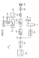
- a control apparatus 219 with respect to the hydraulic cylinders 13L and 13R mentioned above will be explained with reference to Fig. 12.
- a control of an AC servo motor 223 corresponding to a servo motor rotating a bidirectional piston pump 221 corresponding to a bidirectional fluid pump for the right hydraulic cylinder 13R will be explained as follows.
- a ram moving speed pattern command portion 225 instructing a moving speed pattern, for example, of the upper table 5U corresponding to the ram, and in this ram moving speed pattern command portion 225, an upward and downward movement of the upper table 5U is instructed according to a moving speed pattern shown in Fig. 12. Further, a command position counter 227 reads a command position of the upper table 5U on the basis of a command pattern given from the ram moving speed pattern command portion 225.
- a position counter 229 reads an actual position signal given from the linear scale 11 (the ram position detecting means) detecting the position of the upper table 5U so as to feed back, and an adder 231 adds a feed-back signal and the command position read by the command position counter 227 mentioned above so as to compare.
- a ram motion gain determining portion 233 determines a ram motion gain on the basis of a signal added by the adder 231.
- a servo motor rotational number command portion 235 is connected to the ram motion gain determining portion 233, a signal given from the servo motor rotational number command portion 235 is amplified by an amplifier 237 and a command is output to the AC servo motor 223.
- a pressure sensor 239 provided in the bidirectional piston pump 221, a computing portion 241 computing a change amount of pressure on the basis of a pressure given from the pressure sensor 239, and a memory 243 storing a relation between a pressure and a ram moving speed and a relation between a change amount of pressure and a ram moving speed which are described later, are connected to a ram speed cramp value determining portion 245 determining a moving speed of the upper table 5U corresponding to the ram in the manner mentioned below.
- This ram speed cramp value determining portion 245 is connected to a servo motor rotational number command portion 235 instructing a rotational number of the AC servo motor 223 corresponding to the ram moving speed determined by the ram motion gain determining portion 233.
- Fig. 13 there is shown an absolute amount PQ (shown by a solid line in Fig. 13) of the pressure of the bidirectional piston pump 221 and a change amount PV (shown by a single-dot chain line in Fig. 13) of the pressure in the case of executing the bending process.
- the absolute amount PQ of the pressure starts increasing at a time T1 when the punch P is brought into contact with the work, and the absolute amount PQ of the pressure gradually increases during the bending process.
- a first derivative corresponding to the change amount PV of the pressure rapidly rises up from the time T1 when the punch P is brought into contact with the work, and becomes substantially fixed during the period when the bending process is executed at a fixed pressure. Further, when the absolute amount PQ of the pressure becomes fixed, the change amount PV of the pressure becomes zero.
- a ram moving speed VR which is previously stored in the memory 243 taking the noise of the bidirectional piston pump 221 into consideration, and should be set with respect to the change amount PV of the pressure.
- a ram moving speed VR which is previously stored in the memory 243 taking the noise of the bidirectional piston pump 221 into consideration, and should be set with respect to the absolute amount PQ of the pressure.
- a value A1 of the change amount PV of the pressure and a value A2 of the absolute amount PQ of the pressure in a time Ti are calculated in the graph shown in Fig. 13, and ram moving speed B1 and B2 to be set are respectively calculated on the basis of Figs. 14 and 15.
- the ram speed clamp value is instructed to the AC servo motor 223.
- the structure is made such that the ram moving speed B1 is employed, and the rotational number corresponding to the smaller value between the ram moving speed B1 and the command value computed by the ram motion gain determining portion 233 is instructed to the AC servo motor 223.
- the command position counter 227 reads the command position of the upper table 5U according to the pattern given from the ram moving speed pattern command portion 225, this position and the actual position read by the position counter 229 on the basis of the position signal of the linear scale 11 are compared by the adder 231, and the ram motion gain determining portion 233 determines the gain.
- the servo motor rotational number command portion 235 compares the rotational number corresponding to the ram speed determined by the ram speed clamp value determining portion 245 taking the absolute amount of the pressure and the change amount of the pressure detected by the pressure sensor 239 into consideration with the rotational number computed by the ram motion gain determining portion 233, instructs the smaller rotational number to the AC servo motor 223, and rotates the bidirectional piston pump 221.
- this invention can be carried out according to the other aspects by executing a suitable modification without being limited by the embodiment mentioned above of the invention. That is, in the embodiment of the invention mentioned above, the press brake 1 moving the upper table 5U upward and downward as the ram so as to execute the bending process has been explained, however, absolutely the same matters are applied to a type moving the lower table 5L upward and downward so as to execute the bending process.
Landscapes
- Engineering & Computer Science (AREA)
- Mechanical Engineering (AREA)
- Chemical & Material Sciences (AREA)
- Analytical Chemistry (AREA)
- Physics & Mathematics (AREA)
- Fluid Mechanics (AREA)
- General Engineering & Computer Science (AREA)
- Bending Of Plates, Rods, And Pipes (AREA)
- Control Of Presses (AREA)
- Fluid-Pressure Circuits (AREA)
Applications Claiming Priority (5)
| Application Number | Priority Date | Filing Date | Title |
|---|---|---|---|
| JP31598399 | 1999-11-05 | ||
| JP31598399A JP4558867B2 (ja) | 1999-11-05 | 1999-11-05 | プレスブレーキにおけるラム移動方法およびこのラム移動方法を用いたプレスブレーキ |
| JP31742299A JP4334090B2 (ja) | 1999-11-08 | 1999-11-08 | 油圧シリンダの双方向流体ポンプ制御方法およびこの双方向流体ポンプ制御方法を用いたプレスブレーキ |
| JP31742299 | 1999-11-08 | ||
| PCT/JP2000/007732 WO2001034317A1 (fr) | 1999-11-05 | 2000-11-02 | Presse-plieuse et procede de commande de pompe a ecoulement bidirectionnel du cylindre hydraulique de la presse-plieuse |
Publications (3)
| Publication Number | Publication Date |
|---|---|
| EP1232810A1 true EP1232810A1 (de) | 2002-08-21 |
| EP1232810A4 EP1232810A4 (de) | 2003-07-02 |
| EP1232810B1 EP1232810B1 (de) | 2005-08-31 |
Family
ID=26568487
Family Applications (1)
| Application Number | Title | Priority Date | Filing Date |
|---|---|---|---|
| EP00971751A Expired - Lifetime EP1232810B1 (de) | 1999-11-05 | 2000-11-02 | Biegepresse und verfahren zum steuern einer bidirektionalen flüssigkeitspumpe eines hydraulikzylinders einer biegepresse |
Country Status (7)
| Country | Link |
|---|---|
| US (1) | US6874343B1 (de) |
| EP (1) | EP1232810B1 (de) |
| KR (1) | KR100478111B1 (de) |
| CN (1) | CN1184027C (de) |
| DE (1) | DE60022383T2 (de) |
| TW (1) | TW491738B (de) |
| WO (1) | WO2001034317A1 (de) |
Cited By (3)
| Publication number | Priority date | Publication date | Assignee | Title |
|---|---|---|---|---|
| AT503644B1 (de) * | 2006-09-25 | 2007-12-15 | Trumpf Maschinen Austria Gmbh | Verfahren zum betrieb einer biegepresse, insbesondere abkantpresse |
| WO2012055579A1 (en) * | 2010-10-27 | 2012-05-03 | Coskunöz Metal Form Makina Endüstri Ve Tic. A.S. | A servo hydraulic press |
| US20200188983A1 (en) * | 2018-12-13 | 2020-06-18 | Lapmaster Wolters Gmbh | Fine blanking press and method for operating the same |
Families Citing this family (19)
| Publication number | Priority date | Publication date | Assignee | Title |
|---|---|---|---|---|
| JP4700801B2 (ja) * | 2000-12-07 | 2011-06-15 | 株式会社アマダ | 曲げ加工方法 |
| US7940613B2 (en) * | 2004-06-15 | 2011-05-10 | Panasonic Corporation | Drive device |
| JP4408844B2 (ja) * | 2005-07-05 | 2010-02-03 | ファナック株式会社 | サーボダイクッションの制御装置 |
| KR101536506B1 (ko) | 2005-09-07 | 2015-07-14 | 암젠 프레몬트 인코포레이티드 | 액티빈 수용체 유사 키나제-1에 대한 인간 모노클로날 항체 |
| KR100841229B1 (ko) | 2007-03-26 | 2008-06-26 | 주식회사 극동이엔지 | 프레스 금형의 인칭 유닛 |
| CN101463849B (zh) * | 2009-01-12 | 2012-05-16 | 天水锻压机床有限公司 | 预弯机液压电液比例控制系统及其控制方法 |
| FR2942983B1 (fr) * | 2009-03-13 | 2011-04-08 | Amada Europ | Presse plieuse pour le pliage de feuilles |
| JP5528984B2 (ja) * | 2010-10-19 | 2014-06-25 | アイダエンジニアリング株式会社 | 機械プレスのプレス荷重制御装置 |
| JP6061607B2 (ja) | 2012-10-17 | 2017-01-18 | 株式会社アマダホールディングス | 油圧式プレスブレーキ |
| DE102014214739B3 (de) * | 2014-07-28 | 2015-12-31 | Trumpf Werkzeugmaschinen Gmbh + Co. Kg | Stanzvorrichtung, verfahren zum stanzen eines werkstücks und computerprogrammprodukt zur durchführung des verfahrens |
| US10871174B2 (en) | 2015-10-23 | 2020-12-22 | Aol | Prime mover system and methods utilizing balanced flow within bi-directional power units |
| US10598193B2 (en) | 2015-10-23 | 2020-03-24 | Aoi | Prime mover system and methods utilizing balanced flow within bi-directional power units |
| DE102016114635B4 (de) | 2016-08-08 | 2018-09-20 | Hoerbiger Automatisierungstechnik Holding Gmbh | Bearbeitungsmaschine |
| CN106424227B (zh) * | 2016-10-12 | 2018-04-03 | 中国空气动力研究与发展中心高速空气动力研究所 | 一种针对多执行器系统的机电液一体化控制方法 |
| EP3311997B1 (de) * | 2016-10-18 | 2024-09-11 | Automation, Press and Tooling, A.P. & T AB | Servohydraulische presse |
| CN106640792A (zh) * | 2016-12-26 | 2017-05-10 | 中国船舶重工集团公司第七〇九研究所 | 一种应用于单出杆液压缸压机的直驱式电液伺服系统 |
| CN108907004A (zh) * | 2017-02-22 | 2018-11-30 | 惠安县信达友工业设计有限公司 | 一种冲压头降温更换装置 |
| CN108746270A (zh) * | 2018-07-12 | 2018-11-06 | 江阴盛鼎机械制造有限公司 | 一种液压折弯机 |
| CN115853931B (zh) * | 2023-03-03 | 2023-05-09 | 太原矿机电气股份有限公司 | 一种限速值可调的限速制动控制系统 |
Family Cites Families (12)
| Publication number | Priority date | Publication date | Assignee | Title |
|---|---|---|---|---|
| US3827328A (en) * | 1972-12-26 | 1974-08-06 | Greenerd Press & Machine Co In | Control system for hydraulic presses |
| DE2808091A1 (de) * | 1978-02-24 | 1979-08-30 | Moog Gmbh | Einrichtung zum daempfen des schnittschlags bei hydraulischen pressen |
| US4797831A (en) | 1986-11-18 | 1989-01-10 | Cincinnati Incorporated | Apparatus for synchronizing cylinder position in a multiple cylinder hydraulic press brake |
| WO1988004990A1 (fr) * | 1986-12-29 | 1988-07-14 | Mitoshi Ishii | Procede de commande d'une presse et servocommande utilisee a cet effet |
| DE3840395C2 (de) * | 1987-12-04 | 1998-12-03 | Amada Co | Steuerung einer Blechbearbeitungspresse |
| CH686119A5 (fr) * | 1991-10-31 | 1996-01-15 | Beyeler Raskin Sa | Procede de reglage de la course du coulisseau d'une presse-plieuse et presse-plieuse comportant un dispositif de reglage pour la mise en oeuvre du procede. |
| JPH05296203A (ja) * | 1992-04-16 | 1993-11-09 | Kobe Steel Ltd | 作業装置における油圧アクチュエータの制御装置 |
| JPH08164500A (ja) * | 1994-12-14 | 1996-06-25 | Nisshinbo Ind Inc | 分散加圧型プレス装置 |
| JPH08168897A (ja) | 1994-12-16 | 1996-07-02 | Nisshinbo Ind Inc | 金型の分割制御が可能なプレス加工機 |
| US5669257A (en) * | 1994-12-28 | 1997-09-23 | Yazaki Corporation | Method of crimping terminal and apparatus for the same |
| JPH09262622A (ja) * | 1996-03-28 | 1997-10-07 | Amada Co Ltd | 板金加工機における圧力コントロール方法およびその装置 |
| JPH10281477A (ja) * | 1997-03-28 | 1998-10-23 | Daewoo Electron Co Ltd | ガスボイラの双方向ポンプ制御方法及び装置 |
-
2000
- 2000-11-02 EP EP00971751A patent/EP1232810B1/de not_active Expired - Lifetime
- 2000-11-02 WO PCT/JP2000/007732 patent/WO2001034317A1/ja not_active Ceased
- 2000-11-02 CN CNB00816357XA patent/CN1184027C/zh not_active Expired - Fee Related
- 2000-11-02 DE DE60022383T patent/DE60022383T2/de not_active Expired - Lifetime
- 2000-11-02 US US10/111,386 patent/US6874343B1/en not_active Expired - Lifetime
- 2000-11-02 KR KR10-2002-7005851A patent/KR100478111B1/ko not_active Expired - Fee Related
- 2000-11-03 TW TW089123171A patent/TW491738B/zh not_active IP Right Cessation
Cited By (4)
| Publication number | Priority date | Publication date | Assignee | Title |
|---|---|---|---|---|
| AT503644B1 (de) * | 2006-09-25 | 2007-12-15 | Trumpf Maschinen Austria Gmbh | Verfahren zum betrieb einer biegepresse, insbesondere abkantpresse |
| WO2012055579A1 (en) * | 2010-10-27 | 2012-05-03 | Coskunöz Metal Form Makina Endüstri Ve Tic. A.S. | A servo hydraulic press |
| US20200188983A1 (en) * | 2018-12-13 | 2020-06-18 | Lapmaster Wolters Gmbh | Fine blanking press and method for operating the same |
| US11878335B2 (en) * | 2018-12-13 | 2024-01-23 | Lapmaster Wolters Gmbh | Fine blanking press and method for operating the same |
Also Published As
| Publication number | Publication date |
|---|---|
| EP1232810A4 (de) | 2003-07-02 |
| KR100478111B1 (ko) | 2005-03-28 |
| US6874343B1 (en) | 2005-04-05 |
| DE60022383T2 (de) | 2006-03-09 |
| WO2001034317A1 (fr) | 2001-05-17 |
| DE60022383D1 (de) | 2005-10-06 |
| EP1232810B1 (de) | 2005-08-31 |
| KR20020053077A (ko) | 2002-07-04 |
| TW491738B (en) | 2002-06-21 |
| CN1402656A (zh) | 2003-03-12 |
| CN1184027C (zh) | 2005-01-12 |
Similar Documents
| Publication | Publication Date | Title |
|---|---|---|
| US6874343B1 (en) | Press brake and method of controlling bidirectional fluid pump of hydraulic cylinder of press brake | |
| JP6670864B2 (ja) | プレスシステム | |
| EP1279488B1 (de) | Verfahren und vorrichtung zur regelung der endposition einer hydraulischen presse sowie verfahren und vorrichtung zur fehlererkennung bei einem geschwindigkeitswahlventil | |
| US6959581B2 (en) | Press brake and ram movement method for press brake | |
| US7036345B2 (en) | Method of monitoring ram speed of press brake, press brake using the method, and method and apparatus for controlling ram position of press brake | |
| CN117759583B (zh) | 泵阀匹配控制方法、泵阀匹配控制系统及控制器 | |
| CN104154053A (zh) | 主缸液压回路系统 | |
| CN120444227A (zh) | 液驱式活塞压缩机及其活塞控制方法、设备和处理器 | |
| JP4558867B2 (ja) | プレスブレーキにおけるラム移動方法およびこのラム移動方法を用いたプレスブレーキ | |
| CN112253579A (zh) | 电液驱动系统控制方法、装置、电子设备及存储介质 | |
| JPH0138651B2 (de) | ||
| JP2002276611A (ja) | 油圧作動システム、板金加工機械、及び産業機械 | |
| JPH08174097A (ja) | 油圧式タレットパンチプレスの油圧回路 | |
| JPH09177135A (ja) | 建設機械等の旋回制御回路 | |
| JPH10216997A (ja) | 直動型プレスの絞り成形加工制御装置及びその方法 | |
| JP4473990B2 (ja) | プレスブレーキ | |
| JPH07275946A (ja) | 折曲げ加工機 | |
| JP2001205342A (ja) | プレスブレーキにおけるラム位置制御方法およびそのラム位置制御装置 | |
| JP2001140807A (ja) | 油圧シリンダの双方向流体ポンプ制御方法およびこの双方向流体ポンプ制御方法を用いたプレスブレーキ | |
| JP4264888B2 (ja) | 圧縮成形機および圧縮成形機の制御方法 | |
| JPH10193198A (ja) | 油圧プレスのブレークスルーの抑制制御装置 | |
| JP2001198623A (ja) | プレスブレーキにおけるラム速度監視方法およびこのラム速度監視方法を用いたプレスブレーキ | |
| JP4587518B2 (ja) | 液圧装置におけるラム移動制御装置 | |
| JP3573835B2 (ja) | 油圧プレス機械におけるラムシリンダ駆動用油圧回路の背圧防止方法およびその装置 | |
| JPH0724530A (ja) | プレスブレーキのラム制御装置 |
Legal Events
| Date | Code | Title | Description |
|---|---|---|---|
| PUAI | Public reference made under article 153(3) epc to a published international application that has entered the european phase |
Free format text: ORIGINAL CODE: 0009012 |
|
| 17P | Request for examination filed |
Effective date: 20020506 |
|
| AK | Designated contracting states |
Kind code of ref document: A1 Designated state(s): AT BE CH CY DE DK ES FI FR GB GR IE IT LI LU MC NL PT SE TR |
|
| A4 | Supplementary search report drawn up and despatched |
Effective date: 20030519 |
|
| RIC1 | Information provided on ipc code assigned before grant |
Ipc: 7B 21D 5/02 A Ipc: 7B 30B 15/16 B |
|
| 17Q | First examination report despatched |
Effective date: 20031208 |
|
| RBV | Designated contracting states (corrected) |
Designated state(s): AT BE CH CY DE FI FR GB IT LI |
|
| GRAP | Despatch of communication of intention to grant a patent |
Free format text: ORIGINAL CODE: EPIDOSNIGR1 |
|
| RBV | Designated contracting states (corrected) |
Designated state(s): DE FI FR GB IT |
|
| RAP1 | Party data changed (applicant data changed or rights of an application transferred) |
Owner name: AMADA COMPANY, LIMITED |
|
| GRAS | Grant fee paid |
Free format text: ORIGINAL CODE: EPIDOSNIGR3 |
|
| GRAA | (expected) grant |
Free format text: ORIGINAL CODE: 0009210 |
|
| AK | Designated contracting states |
Kind code of ref document: B1 Designated state(s): DE FI FR GB IT |
|
| REG | Reference to a national code |
Ref country code: GB Ref legal event code: FG4D |
|
| REF | Corresponds to: |
Ref document number: 60022383 Country of ref document: DE Date of ref document: 20051006 Kind code of ref document: P |
|
| ET | Fr: translation filed | ||
| PLBE | No opposition filed within time limit |
Free format text: ORIGINAL CODE: 0009261 |
|
| STAA | Information on the status of an ep patent application or granted ep patent |
Free format text: STATUS: NO OPPOSITION FILED WITHIN TIME LIMIT |
|
| 26N | No opposition filed |
Effective date: 20060601 |
|
| PGFP | Annual fee paid to national office [announced via postgrant information from national office to epo] |
Ref country code: FI Payment date: 20111122 Year of fee payment: 12 |
|
| PG25 | Lapsed in a contracting state [announced via postgrant information from national office to epo] |
Ref country code: FI Free format text: LAPSE BECAUSE OF NON-PAYMENT OF DUE FEES Effective date: 20121102 |
|
| REG | Reference to a national code |
Ref country code: FR Ref legal event code: PLFP Year of fee payment: 16 |
|
| REG | Reference to a national code |
Ref country code: FR Ref legal event code: PLFP Year of fee payment: 17 |
|
| PGFP | Annual fee paid to national office [announced via postgrant information from national office to epo] |
Ref country code: FR Payment date: 20161118 Year of fee payment: 17 Ref country code: GB Payment date: 20161122 Year of fee payment: 17 Ref country code: DE Payment date: 20161121 Year of fee payment: 17 |
|
| PGFP | Annual fee paid to national office [announced via postgrant information from national office to epo] |
Ref country code: IT Payment date: 20161123 Year of fee payment: 17 |
|
| REG | Reference to a national code |
Ref country code: DE Ref legal event code: R119 Ref document number: 60022383 Country of ref document: DE |
|
| GBPC | Gb: european patent ceased through non-payment of renewal fee |
Effective date: 20171102 |
|
| REG | Reference to a national code |
Ref country code: FR Ref legal event code: ST Effective date: 20180731 |
|
| PG25 | Lapsed in a contracting state [announced via postgrant information from national office to epo] |
Ref country code: IT Free format text: LAPSE BECAUSE OF NON-PAYMENT OF DUE FEES Effective date: 20171102 Ref country code: FR Free format text: LAPSE BECAUSE OF NON-PAYMENT OF DUE FEES Effective date: 20171130 Ref country code: DE Free format text: LAPSE BECAUSE OF NON-PAYMENT OF DUE FEES Effective date: 20180602 |
|
| PG25 | Lapsed in a contracting state [announced via postgrant information from national office to epo] |
Ref country code: GB Free format text: LAPSE BECAUSE OF NON-PAYMENT OF DUE FEES Effective date: 20171102 |