EP1232832A2 - Système d'élimination de copeaux des surfaces d'une machine-outil - Google Patents
Système d'élimination de copeaux des surfaces d'une machine-outil Download PDFInfo
- Publication number
- EP1232832A2 EP1232832A2 EP02002984A EP02002984A EP1232832A2 EP 1232832 A2 EP1232832 A2 EP 1232832A2 EP 02002984 A EP02002984 A EP 02002984A EP 02002984 A EP02002984 A EP 02002984A EP 1232832 A2 EP1232832 A2 EP 1232832A2
- Authority
- EP
- European Patent Office
- Prior art keywords
- fluid
- receptacle
- flow
- swarf
- machine
- Prior art date
- Legal status (The legal status is an assumption and is not a legal conclusion. Google has not performed a legal analysis and makes no representation as to the accuracy of the status listed.)
- Withdrawn
Links
Images



Classifications
-
- B—PERFORMING OPERATIONS; TRANSPORTING
- B23—MACHINE TOOLS; METAL-WORKING NOT OTHERWISE PROVIDED FOR
- B23Q—DETAILS, COMPONENTS, OR ACCESSORIES FOR MACHINE TOOLS, e.g. ARRANGEMENTS FOR COPYING OR CONTROLLING; MACHINE TOOLS IN GENERAL CHARACTERISED BY THE CONSTRUCTION OF PARTICULAR DETAILS OR COMPONENTS; COMBINATIONS OR ASSOCIATIONS OF METAL-WORKING MACHINES, NOT DIRECTED TO A PARTICULAR RESULT
- B23Q11/00—Accessories fitted to machine tools for keeping tools or parts of the machine in good working condition or for cooling work; Safety devices specially combined with or arranged in, or specially adapted for use in connection with, machine tools
- B23Q11/0042—Devices for removing chips
- B23Q11/0057—Devices for removing chips outside the working area
-
- B—PERFORMING OPERATIONS; TRANSPORTING
- B23—MACHINE TOOLS; METAL-WORKING NOT OTHERWISE PROVIDED FOR
- B23Q—DETAILS, COMPONENTS, OR ACCESSORIES FOR MACHINE TOOLS, e.g. ARRANGEMENTS FOR COPYING OR CONTROLLING; MACHINE TOOLS IN GENERAL CHARACTERISED BY THE CONSTRUCTION OF PARTICULAR DETAILS OR COMPONENTS; COMBINATIONS OR ASSOCIATIONS OF METAL-WORKING MACHINES, NOT DIRECTED TO A PARTICULAR RESULT
- B23Q11/00—Accessories fitted to machine tools for keeping tools or parts of the machine in good working condition or for cooling work; Safety devices specially combined with or arranged in, or specially adapted for use in connection with, machine tools
- B23Q11/0042—Devices for removing chips
-
- Y—GENERAL TAGGING OF NEW TECHNOLOGICAL DEVELOPMENTS; GENERAL TAGGING OF CROSS-SECTIONAL TECHNOLOGIES SPANNING OVER SEVERAL SECTIONS OF THE IPC; TECHNICAL SUBJECTS COVERED BY FORMER USPC CROSS-REFERENCE ART COLLECTIONS [XRACs] AND DIGESTS
- Y10—TECHNICAL SUBJECTS COVERED BY FORMER USPC
- Y10T—TECHNICAL SUBJECTS COVERED BY FORMER US CLASSIFICATION
- Y10T409/00—Gear cutting, milling, or planing
- Y10T409/30—Milling
- Y10T409/304088—Milling with means to remove chip
-
- Y—GENERAL TAGGING OF NEW TECHNOLOGICAL DEVELOPMENTS; GENERAL TAGGING OF CROSS-SECTIONAL TECHNOLOGIES SPANNING OVER SEVERAL SECTIONS OF THE IPC; TECHNICAL SUBJECTS COVERED BY FORMER USPC CROSS-REFERENCE ART COLLECTIONS [XRACs] AND DIGESTS
- Y10—TECHNICAL SUBJECTS COVERED BY FORMER USPC
- Y10T—TECHNICAL SUBJECTS COVERED BY FORMER US CLASSIFICATION
- Y10T82/00—Turning
- Y10T82/16—Severing or cut-off
- Y10T82/16098—Severing or cut-off with dust or chip handling
Definitions
- This invention is concerned with improvements relating to machine tools, particularly machine tools during use of which large quantities of cut material (conventionally termed "swarf') are produced.
- the invention has been devised in relation to a vertical cutting machine, particularly for the production of machined metal parts, in which context the invention will hereinafter be described. It is however to be understood that the invention is not limited to this specific context, and may be utilised generally, eg. in turning, milling, drilling, reaming, grinding machines, or in machines designed to operate on non-metallic material, eg. in the production of plastic workpieces.
- swarf' is to be understood as applying to all cut materials, including both metal and plastics.
- a cuffing tool In the production of a machined part a cuffing tool, conventionally rotated at high speed, is traversed across a workpiece secured to a machine table mounted for movement above a machine bed, the cutting tool removing metal from the workpiece in stages, the removed metal constituting scrap or swarf.
- a cutting fluid is conventionally directed to the interface between the cutting tool and the workpiece, providing lubrication for the cutting action, washing cut material from the immediate vicinity of the interface, and to maintain the temperature of the cutting tool at a preferable low temperature.
- Cut material falls away from the workpiece onto surfaces of the machine, such as the machine bed or floor, or a cover for the internal machinery of the machine, and particularly for workpieces of aluminium and similar materials having a high cut rate, the build up of swarf can be considerable.
- the management system may comprise removal means in the form of scraper bars which move across the surface to scrape the material onto a conveyor belt, or means to produce liquid flow streams to wash the material onto the conveyor belt, or both. Where wash bars are utilised, it is difficult to locate these without interference with the normal operational movement of the machine parts, and they may easily be knocked out of position in use.
- cutting fluids may comprise oxidation inhibitors, bacteriological inhibitors, lubricants etc., and are thus not inexpensive, and there are thus further disadvantages in utilising high flow rates of liquid for the removal of the scrap.
- a method of cleaning cut material from a machine tool in which a cleaning fluid is flowed across surfaces of the machine intermittently.
- the cleaning fluid may be flowed at a higher volume than would otherwise be desirable or practical.
- a higher flow rate may be utilised periodically to wash larger volumes of swarf from the machine surfaces.
- cleaning fluid flows across one of the machine surfaces to a channel leading to a sump and further cleaning fluid is flowed through the channel to the sump intermittently.
- intermittent flows of cleaning fluid may be used to sweep swarf from the cutting surface to the outside of the machine.
- a continuous flow of cleaning fluid is utilised in the method, the cleaning fluid flowing into a receptacle from which fluid flows periodically in a cleaning operation.
- the substantial volume is at least 2 litres and is preferably 5 litres or more.
- the intermittent flow from the receptacle may be achieved by the use of valve mechanism, eg. periodic-operating valve mechanism, but preferably is achieved by the use of a syphon, thus obviating the use of moving parts.
- valve mechanism eg. periodic-operating valve mechanism
- a double syphon is utilised, enabling a high outflow through a large diameter pipe to be achieved with a relatively slow in-feed rate.
- the quantity which is flowed intermittently is between three and twenty litres, conveniently between five and ten litres, and is conveniently outflowed over a period of five seconds or less, eg. two or three seconds.
- outflow rate will typically fall within the range 36-600 litres per minute.
- time interval between successive outflows is between thirty seconds and two minutes, conveniently an outflow occurring every minute or thereabouts.
- outflows are provided at a plurality of parts of the machine, to ensure swarf is washed from all appropriate or desirable surfaces, and in a typical machine four such outflows may be utilised, with independent flow rates and time intervals selected in accordance with the location of the outflow and the quantities to be cleared.
- a machine tool comprising means to flow fluid across one or more surfaces of the machine to remove swarf, said means comprising:
- the delivery means comprises a pump operative to pump fluid to the receptacle at a substantially constant flow rate of between 2 and 10 litres per minute, conveniently between 5 and 7 litres per minute, and the outflow means is operative to cause fluid to be delivered therefrom intermittently at a higher rate than the delivery of fluid thereto.
- said outflow means is operative to cause the receptacle to discharge its contents subsequent to the accumulation in the container of a sufficient quantity of fluid to produce an outflow of a desired intensity (volume or velocity).
- said outflow means is operative to produce such an outflow at an interval of between thirty seconds and one hundred and twenty seconds.
- the receptacle discharges its contents in a period of time conveniently of between 2 and 7 seconds, conveniently about 3 to 5 seconds, and conveniently the volume of fluid discharged is substantially the whole contents of the receptacle.
- the machine comprises a plurality of such fluid receptacles, such delivery means, such flow line and such outflow means to cause liquid to flow from the receptacle, operative to cause fluid to flow across a plurality of surfaces of the machine to remove swarf.
- the machine comprises a channel leading to a sump into which cutting fluid and swarf are flowed, in which at least one of said plurality of fluid receptacles, delivery means, flow line, and outflow means is operative to cause fluid to flow through the channel intermittently.
- the fluid and swarf are separated in the sump.
- a pump means Conveniently located in the sump means is a pump means operative to deliver fluid from the sump to the or each receptacle at a substantially constant flow rate.
- Such pump means is also operative to delivery fluid to the cutting head of the machine.
- a swarf management system comprising a fluid receptacle, pump means to deliver fluid from a sump to the receptacle, a flow line extending from the receptacle from which fluid flow may be directed across a machine surface for the removal of swarf therefrom, and outflow means to cause fluid to flow from the receptacle through the flow line only intermittently.
- the machine which is the first embodiment of this invention is a machine tool of conventional type, which will be described hereinafter only in general terms insofar as it is necessary to understand the present invention.
- the machine comprises a floor plate 6 above which a machine bed 8 is mounted, and mounted for movement across the machine bed is a machine table 10, to which a workpiece (not shown) may be secured in conventional manner.
- a column 12 Extending upwardly from the machine bed is a column 12, comprising guideways 14 on which a cutting head (not shown) may be mounted for movement towards and away from the machine table.
- the construction and arrangement will conventionally be such as to permit relative movement to take place between a tool carried by the tool head and a workpiece mounted on the machine table in at least three orthogonal axes, to permit the production of a machine part to a desired design, from a workpiece, the moving parts of the machine being enclosed within a plastic or metal cover 36, shown in dotted lines in Figure 1.
- a cover 7 mounted on the floor plate 6 is a cover 7, within which internal machinery for the machine is located, including for example the machine motor, ball screw drives, and control devices.
- cut material typically known as and referred to hereinafter as swarf
- swarf cut material
- the machine table onto the cover, onto the floorplate, and onto other surfaces of the machine, and it is necessary for this material to be removed.
- a housing 18 into the interior of which swarf may be caused to move, either by the use of cleaning fluid in conventional manner, or by the use of scraper bars, or by hand.
- each housing 18 provides a sump chamber 19 (see Figure 2), into which cutting liquid and cut material may pass conveniently through an opening 20.
- a conveyor 22 conveniently a scraper conveyor, operative to transfer solid material from the sump chamber and through an upwardly inclined section 30, to a discharge point 32, from which cut material may be deposited into a container, for accumulation and subsequent removal.
- cutting fluid flows backwardly into the sump chamber.
- a pump chamber 24 Located in the sump chamber is a pump chamber 24, into which fluid flows from the sump chamber, through a filter material, and from which fluid is flowed by the use of a pump 26, as will hereinafter be described.
- Liquid which accumulates in the left hand sump chamber 18 a is delivered to the right hand sump chamber 18 b by a flow pipe, allowing a single pump 26 to be utilised in the operation of the machine.
- the pump operates, in the preferred embodiment, at a flow rate of 25 litres per minute, 5 litres per minute for each of the receptacles 40, and 5 litres per minute being directed to the cutting head of the machine, for lubrication of the cutting tool during operation.
- two pumps of smaller capacity may be utilised, one operative within each of the two sump chambers.
- a fluid discharge receptacle 40 Located at any convenient position on the machine, typically at the four locations shown in Figure 1 of the drawings, is a fluid discharge receptacle 40, to which fluid is delivered from the pump 26, and from which fluid flows through an outlet duct 48 directed towards those surfaces of the machine where it is desired to remove accumulated swarf.
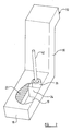
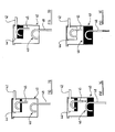
- the receptacle 40 is in the form of a double-syphon, comprising a first-stage syphon 44 and a second-stage syphon 46 (see figure 3 a ).
- a pipe 42 of narrow bore, conveniently provided by hose having diameter of 1 ⁇ 2" (12.5mm), through which fluid is flowed from pump 26 at a rate of 5 litres per minute.
- the capacity of the first-stage syphon 44 is typically 2 litres, and thus after 24 seconds or so the first-stage syphon is filled, and liquid is discharged therefrom through the outlet 45 of the first-stage syphon, into the second-stage syphon, conveniently utilising a hose of larger diameter than the inlet 42, typically of 1" diameter (25mm), (see Figure 3 b ).
- the hose forming the syphons has a flattened, generally oval cross-section at the top of its loop, which is wider in the horizontal direction to the vertical direction. This promotes the syphon action and prevents air bubbles forming in the hose.
- the capacity of the second-stage syphon 46 is typically 5 litres, and thus after the dispensing into the second stage syphon 46 of (typically) 3 outflows from the first-stage syphon, the second-stage syphon 46 is filled, and liquid is outflowed therefrom through the hose 48, which may be of larger diameter, conveniently 11 ⁇ 2" (38mm), (see figure 3 d ).
- This enables substantially the entire contents of the second-stage syphon 46 to be dispensed through the outlet 48 within 2 or 3 seconds, producing a high flow rate across the surfaces of the machine, and ensuring a thorough removal of accumulated swarf, to flow onto the floorplate, and through the openings 20 into the sump chambers 19.
- the machine which is the first embodiment of this invention comprises four receptacles 40, to each of which liquid is delivered from the pump 26 at the low flow rate of (typically) 5 litres per minute, each of the receptacles 40 producing a high intermittent flow of liquid to wash the surfaces of the machine clear of accumulated swarf.
- FIGS 4, 5 and 6 show a machine which is the second embodiment of this invention, generally of conventional type, which will be described hereinafter only in general terms insofar as it is necessary to understand the present invention.
- the machine is generally similar to the first embodiment, but conveyers to each side of the machine are replaced by a front flushing system.
- the machine has three receptacles 54, two of which indicated by the numerals 54 a and 54 b are connected to outlet ducts 56 which are located at either side of the machine, towards the rear of the machine.
- the outlets ducts 56 extend to side gulleys 58, which slope towards a front gully 60, which has a square cross-section.
- the third receptacle 54 is connected to an outlet duct 62 extending to one side of the front gully 60.
- the gully slopes down to an outlet 64 at the other side of the machine.
- swarf is carried across the machine to the outlet 64.
- the receptacle 54 c which serves the front flushing system 52 is a double syphon system similar to those described in the first embodiment, but preferably having a larger capacity with a first-stage syphon of approximately 2 litres capacity and a second-stage syphon of approximately eight litres capacity. Liquid is delivered to the receptacle from a pump 66, which also delivers liquid to the cutting head and to the each of the other two receptacles, at a rate of approximately 5 litres per minute.
- the hose which carries outflow from the front flushing receptacle 54 c is sized to provide a peak flow from the receptacle of approximately 200 litres per minute, and to outflow the whole of the contents of the second-stage syphon within 2 or 3 seconds. This provides a flow with sufficient force to move the swarf along the front gully 60 of the machine.
- the front gully 60 and the side gullies 58 are polished, having a smooth surface which enables swarf to flow more easily through the gullies.
- fluid and swarf flows through the outlet 64 to a sump 70.
- the swarf is then elevated by an auger screw 68 to a height of approximately 1 m. This allows a swarf bin 85 (shown in dotted lines in Figure 6) to be placed under the outlet to collect the swarf.
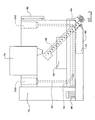
- Figure 6 shows a top view of the front flushing system.
- the machine tool is shown at the centre of the Figure, comprising a support column 72, a cutting head 74 and a machining table 76.
- Swarf is flushed to either side of the machining table 76 by the flow of fluid from the cutting head of the machine, and flows into the side gullies 58.
- the intermittent flushing system described earlier flows the swarf into the front gully 60 and from there through the outlet 64 into the sump 70.
- the sump 70 has angled internal walls as shown to aid swarf removal, and leads to the system pump 66 which recirculates the fluid back to the three receptacles 54 for the flushing system and to the cutting head.
- a control screen is situated at the front of the machine. It provides an overview of the machine's operation and allows the operator to control the machine accordingly.
- the intermittent flow rate is achieved by the use of syphons, other means may be utilised to put the invention into practice if desired.
- the receptacle to which fluid is delivered may be provided with a valve mechanism, conveniently time-operated, which may be caused to open at pre-determined periods, to cause the contents of the receptacle to be discharged in a short period of time, to produce the desired "flushing" action
Landscapes
- Engineering & Computer Science (AREA)
- Mechanical Engineering (AREA)
- Cleaning By Liquid Or Steam (AREA)
- Auxiliary Devices For Machine Tools (AREA)
Applications Claiming Priority (2)
| Application Number | Priority Date | Filing Date | Title |
|---|---|---|---|
| GB0103959 | 2001-02-17 | ||
| GBGB0103959.3A GB0103959D0 (en) | 2001-02-17 | 2001-02-17 | Machine tools |
Publications (2)
| Publication Number | Publication Date |
|---|---|
| EP1232832A2 true EP1232832A2 (fr) | 2002-08-21 |
| EP1232832A3 EP1232832A3 (fr) | 2003-02-05 |
Family
ID=9908971
Family Applications (1)
| Application Number | Title | Priority Date | Filing Date |
|---|---|---|---|
| EP02002984A Withdrawn EP1232832A3 (fr) | 2001-02-17 | 2002-02-11 | Système d'élimination de copeaux des surfaces d'une machine-outil |
Country Status (3)
| Country | Link |
|---|---|
| US (1) | US20020152852A1 (fr) |
| EP (1) | EP1232832A3 (fr) |
| GB (1) | GB0103959D0 (fr) |
Cited By (1)
| Publication number | Priority date | Publication date | Assignee | Title |
|---|---|---|---|---|
| CN109759890A (zh) * | 2019-03-25 | 2019-05-17 | 杭州富阳孙氏机床有限公司 | 一种用于车床加工的碎屑收集装置 |
Families Citing this family (3)
| Publication number | Priority date | Publication date | Assignee | Title |
|---|---|---|---|---|
| CN104959649B (zh) * | 2015-06-14 | 2017-09-15 | 朱新洁 | 一种用于孔深加工的工装组件 |
| CN111673526A (zh) * | 2020-04-14 | 2020-09-18 | 桐庐睦德机械制造有限公司 | 一种偏心式多工位钻铣机床 |
| JP2023131659A (ja) * | 2022-03-09 | 2023-09-22 | ブラザー工業株式会社 | 制御装置、工作機械、制御方法及びコンピュータプログラム |
Family Cites Families (9)
| Publication number | Priority date | Publication date | Assignee | Title |
|---|---|---|---|---|
| GB380936A (en) * | 1931-09-21 | 1932-09-29 | Edward Albert Caston | Improved flushing tank for railway carriages, public latrines or domestic use |
| BE562452A (fr) * | 1957-11-18 | 1900-01-01 | ||
| JPS59175939A (ja) * | 1983-03-24 | 1984-10-05 | Fuji Heavy Ind Ltd | 工作機械の加工基準面清掃装置 |
| DE4030736A1 (de) * | 1990-09-28 | 1992-04-02 | Klessmann Ima Norte Maschfab | Werkzeugmaschine mit einer kuehlung des werkzeugs mittels eines fluessigen kuehlmittels |
| DE4031993A1 (de) * | 1990-10-09 | 1992-04-16 | Chiron Werke Gmbh | Werkzeugmaschine |
| DE4209912A1 (de) * | 1991-03-30 | 1992-10-01 | Hoestemberghe & Kluetsch Gmbh | Trennschleifmaschine zum trennen von blechen |
| US5205686A (en) * | 1992-02-07 | 1993-04-27 | Fadal Engineering Co. | Apparatus and method for hydraulically fed cuttings removal and collection for cutting type machine tools |
| US5586848A (en) * | 1995-05-02 | 1996-12-24 | The Gleason Works | Machine tool chip removal system |
| FR2751254B1 (fr) * | 1996-07-19 | 1998-08-21 | Renault | Dispositif pour enlever les copeaux projetes par la tete d'usinage d'une machine outil |
-
2001
- 2001-02-17 GB GBGB0103959.3A patent/GB0103959D0/en not_active Ceased
-
2002
- 2002-02-11 EP EP02002984A patent/EP1232832A3/fr not_active Withdrawn
- 2002-02-14 US US10/076,024 patent/US20020152852A1/en not_active Abandoned
Cited By (1)
| Publication number | Priority date | Publication date | Assignee | Title |
|---|---|---|---|---|
| CN109759890A (zh) * | 2019-03-25 | 2019-05-17 | 杭州富阳孙氏机床有限公司 | 一种用于车床加工的碎屑收集装置 |
Also Published As
| Publication number | Publication date |
|---|---|
| GB0103959D0 (en) | 2001-04-04 |
| US20020152852A1 (en) | 2002-10-24 |
| EP1232832A3 (fr) | 2003-02-05 |
Similar Documents
| Publication | Publication Date | Title |
|---|---|---|
| US4440642A (en) | Separating and cleaning apparatus for cooling lubricant | |
| EP3038727B1 (fr) | Séparateur liquide-solide | |
| JP3851694B2 (ja) | 冷却潤滑剤の浄化装置 | |
| US20120118278A1 (en) | Cutting machine with a liquid lubrication delivery system having a controlled liquid level | |
| CN101316681B (zh) | 过滤装置 | |
| JP6007309B1 (ja) | 濾過装置 | |
| US5205686A (en) | Apparatus and method for hydraulically fed cuttings removal and collection for cutting type machine tools | |
| US5223156A (en) | Process for removing waste from fluid media with production residues | |
| US4394264A (en) | Magnetic liquid filter | |
| US11964353B2 (en) | Machine debris clean out system | |
| EP1232832A2 (fr) | Système d'élimination de copeaux des surfaces d'une machine-outil | |
| JP5526253B1 (ja) | 濾過装置 | |
| US7364032B2 (en) | Chip discharge system | |
| CN110103070B (zh) | 具有废屑清理功能的机床用平床身 | |
| JP5240877B2 (ja) | 濾過方法、濾過機及び当該濾過機が搭載されたチップコンベヤ装置 | |
| JP2018176308A (ja) | 洗浄装置及び洗浄方法 | |
| JP2020171988A (ja) | チップ搬送コンベヤ | |
| KR20170033688A (ko) | 칩 및 오일 제거기능을 가지는 절삭유 공급장치 | |
| EP4029834B1 (fr) | Dispositif de traitement de l'eau de meulage pour le traitement de verres de lunettes | |
| JP3117484U (ja) | 切削屑分離装置およびクーラント装置 | |
| CA2479331C (fr) | Systeme d'evacuation de copeaux | |
| CN212071274U (zh) | 一种数控车床的除屑机构 | |
| JPH07155649A (ja) | スプレー装置 | |
| JPH05261221A (ja) | 濾過槽に配したフィルターエレメントの逆洗装置 | |
| JPH0987873A (ja) | 固体粒子の排出方法および装置 |
Legal Events
| Date | Code | Title | Description |
|---|---|---|---|
| PUAI | Public reference made under article 153(3) epc to a published international application that has entered the european phase |
Free format text: ORIGINAL CODE: 0009012 |
|
| AK | Designated contracting states |
Kind code of ref document: A2 Designated state(s): AT BE CH CY DE DK ES FI FR GB GR IE IT LI LU MC NL PT SE TR |
|
| AX | Request for extension of the european patent |
Free format text: AL;LT;LV;MK;RO;SI |
|
| PUAL | Search report despatched |
Free format text: ORIGINAL CODE: 0009013 |
|
| AK | Designated contracting states |
Designated state(s): AT BE CH CY DE DK ES FI FR GB GR IE IT LI LU MC NL PT SE TR |
|
| AX | Request for extension of the european patent |
Extension state: AL LT LV MK RO SI |
|
| 17P | Request for examination filed |
Effective date: 20030801 |
|
| AKX | Designation fees paid |
Designated state(s): AT BE CH CY DE DK ES FI FR GB GR IE IT LI LU MC NL PT SE TR |
|
| 17Q | First examination report despatched |
Effective date: 20041122 |
|
| STAA | Information on the status of an ep patent application or granted ep patent |
Free format text: STATUS: THE APPLICATION IS DEEMED TO BE WITHDRAWN |
|
| 18D | Application deemed to be withdrawn |
Effective date: 20050405 |