EP1233131B1 - Commande de séquence de fermeture - Google Patents
Commande de séquence de fermeture Download PDFInfo
- Publication number
- EP1233131B1 EP1233131B1 EP02003436A EP02003436A EP1233131B1 EP 1233131 B1 EP1233131 B1 EP 1233131B1 EP 02003436 A EP02003436 A EP 02003436A EP 02003436 A EP02003436 A EP 02003436A EP 1233131 B1 EP1233131 B1 EP 1233131B1
- Authority
- EP
- European Patent Office
- Prior art keywords
- sequence controller
- closure sequence
- leaf
- door
- blocking member
- Prior art date
- Legal status (The legal status is an assumption and is not a legal conclusion. Google has not performed a legal analysis and makes no representation as to the accuracy of the status listed.)
- Expired - Lifetime
Links
- 230000000903 blocking effect Effects 0.000 claims description 29
- 230000006835 compression Effects 0.000 claims description 5
- 238000007906 compression Methods 0.000 claims description 5
- 238000005452 bending Methods 0.000 claims 1
- 230000001419 dependent effect Effects 0.000 description 1
- 238000011161 development Methods 0.000 description 1
- 230000018109 developmental process Effects 0.000 description 1
- 230000000694 effects Effects 0.000 description 1
- 230000002035 prolonged effect Effects 0.000 description 1
- 230000007704 transition Effects 0.000 description 1
Images




Classifications
-
- E—FIXED CONSTRUCTIONS
- E05—LOCKS; KEYS; WINDOW OR DOOR FITTINGS; SAFES
- E05F—DEVICES FOR MOVING WINGS INTO OPEN OR CLOSED POSITION; CHECKS FOR WINGS; WING FITTINGS NOT OTHERWISE PROVIDED FOR, CONCERNED WITH THE FUNCTIONING OF THE WING
- E05F5/00—Braking devices, e.g. checks; Stops; Buffers
- E05F5/12—Braking devices, e.g. checks; Stops; Buffers specially for preventing the closing of a wing before another wing has been closed
-
- E—FIXED CONSTRUCTIONS
- E05—LOCKS; KEYS; WINDOW OR DOOR FITTINGS; SAFES
- E05Y—INDEXING SCHEME ASSOCIATED WITH SUBCLASSES E05D AND E05F, RELATING TO CONSTRUCTION ELEMENTS, ELECTRIC CONTROL, POWER SUPPLY, POWER SIGNAL OR TRANSMISSION, USER INTERFACES, MOUNTING OR COUPLING, DETAILS, ACCESSORIES, AUXILIARY OPERATIONS NOT OTHERWISE PROVIDED FOR, APPLICATION THEREOF
- E05Y2201/00—Constructional elements; Accessories therefor
- E05Y2201/60—Suspension or transmission members; Accessories therefor
- E05Y2201/622—Suspension or transmission members elements
- E05Y2201/686—Rods, links
-
- E—FIXED CONSTRUCTIONS
- E05—LOCKS; KEYS; WINDOW OR DOOR FITTINGS; SAFES
- E05Y—INDEXING SCHEME ASSOCIATED WITH SUBCLASSES E05D AND E05F, RELATING TO CONSTRUCTION ELEMENTS, ELECTRIC CONTROL, POWER SUPPLY, POWER SIGNAL OR TRANSMISSION, USER INTERFACES, MOUNTING OR COUPLING, DETAILS, ACCESSORIES, AUXILIARY OPERATIONS NOT OTHERWISE PROVIDED FOR, APPLICATION THEREOF
- E05Y2900/00—Application of doors, windows, wings or fittings thereof
- E05Y2900/10—Application of doors, windows, wings or fittings thereof for buildings or parts thereof
- E05Y2900/13—Type of wing
- E05Y2900/132—Doors
Definitions
- the invention relates to a closing sequence controller for a door comprising a fixed leaf and a leaf, in particular a fire door, according to the preamble of claims 1, and 8.
- Two-leaf doors of the type mentioned above overlap each other in the central region, so that the one wing forming a living wing has a stop for the other, the active leaf door forming, with their tight closure a certain closing sequence is required if the door should be properly closed.
- closing sequence control are used, which always ensures the necessary for the aforementioned proper closing order of the transitions of the two wings in the closed position.
- a certain sequence of closing movement of both door leaves is therefore necessary to allow the usually provided with a lock power leaves only in the closed position, when the door stop forming, usually the strike plate or the like having the passive leaf is closed.
- a closing sequence controller is known from DE 33 36 739 C2.
- the slider of the active leaf and the locking member on their sides facing a saw toothing, the inclined tooth surfaces have in a the opening of the active leaf in befindlichem in the unlock position blocking member direction.
- DE 195 45 401 A1 discloses a closing sequence controller specified in the preamble of claims 1 and 8 Art., Wherein the clamping rod and the thrust member are guided laterally past the base body, which carries the locking member.
- the non-prepublished EP 1111178 A2 shows a further closing sequence control, in which the clamping effect is generated by a rotatable clamping shoe or clamping wedge.
- the non-prepublished EP 1126118 A2 shows a Scht manfofgeregetung with a spring-loaded ball, which is supported on another ball, which can be sunk depending on the open position of the inactive leaf in the recess of a slider.
- the closing sequence controller is characterized by an uncomplicated structure with few components, which nevertheless always ensures that the inactive leaf is transferred in front of the active leaf in the closed position. This is achieved primarily by the fact that the locking member is always biased in the direction of the blocking position, so that it requires a conscious solution to this blocking position to move the active leaf in the closed position can.
- the closing sequence controller is installed within the known sliding guide.
- the locking member is contained within a base body, wherein the base body can be retrofitted within the sliding guide.
- a door 2 with two wings is shown by way of example in or on a wall or a wall-fixed door frame 7, of which a wing 3 forms the inactive leaf and a wing 4 the active leaf.
- Both the inactive leaf 3 and the moving leaf 4 are equipped with door closers 19 and 20, wherein the door leaves of the illustrated embodiment are each connected to a top door closer, whose closer shaft, not shown, in each case with a pivot arm 5 and 6 is rotatably connected.
- the free end of the pivot arm 5 and 6 is a z. B. on the door frame 7 above the wings 3, 4 arranged rail-like slide 10 out.
- Instead of overhead door closers and rotary vane drives can be used.
- each pivoting arm 5 and 6 At the free end of each pivoting arm 5 and 6, a slider 9 and 11 is arranged on a pin, not shown, which engages in the guide chamber of the sliding guide 10 longitudinally displaceable.
- the first embodiment of the closure sequence controller 1 according to the invention which can be used according to the door arrangement described in FIG. 1, will be described in more detail below. It is understood that the closing sequence controller 1 in addition to the features making up the particular features of the present invention, of course, all other known features, such as mechanical or electrical type drives, possibly required sensors and control devices may have.
- the closing sequence controller 1 initially has a first slider 9 which is connected to the door frame end of the swing arm 6 of the active leaf 4. As already explained, this first slider 9 is slidably mounted in the slide frame 10 mounted in the door frame 7.
- the second slider 11 is connected to the door frame side end of the swing arm 5 of the passive leaf 3. It is also slidably disposed in the sliding guide 10.
- the slider 11 has a thrust member 12, which is formed in the illustrated embodiment as a release rod, which is fixedly connected to the slider 11.
- the trigger bar 12 in turn has a tip 16 which is engageable with a mounted in the base body 13 locking member 8 and disengaged.
- the trip bar 12 is inserted into the main body 13 and the tip 16 is preferably bevelled.
- the locking member 8 is always biased in the direction of its blocking position, for which purpose a specified in the figures with 8a suitable spring element is provided.
- a flexurally elastic clamping bracket 17 which is designed in the manner of a cantilever beam, is attached to the base body 13.
- the clamping bracket 17 is angled towards the inactive leaf side, accordingly has there a ramp 18, which is provided with a recess through which the pusher member 12 can engage through into the interior of the clamping bracket 17.
- the locking member 8 is arranged, which is designed as a pinch roller.
- the locking member 8 is biased by means of a spring element 8a, preferably in the form of a helical compression spring, in the direction of its locking or clamping position.
- a spring element 8a preferably in the form of a helical compression spring
- the locking member 8 is pressed onto the ramp 18 and from this with its clamping surface 14 in the direction of the associated surface region of the clamping rod 15 which passes through the base body 13 and the clamping bracket 17 and the slider 11 therethrough.
- the pinch roller 8 with the clamping rod 15 and the tapered end or the ramp 18 of the clamping bracket 17 forms an active pairing.
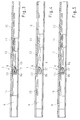
- FIGS. 2A and 2B represents the closed position of the door leaves 3 and 4 of the door 2 according to FIG. 1.
- both sliders 9 and 11 are in their initial position and the trip bar 12 pushes the pinch roller 8 out of its locked position.
- the slider 11 of the passive blade 3 is in this position, the slider 9 of the active leaf 3 and thus the active leaf 3 itself is free to move. If the active leaf 3 is opened, it can close normally without actuating the closing sequence controller 1, since the trigger bar 12 prevents the clamping rod 15 from becoming clamped by the blocking element 8.
- the locking member 8 follows due to the action of the compression spring of the trip bar until the locking member 8 is in its clamping position in which no contact between the trigger bar 12 and locking member 8 is made.
- the slider 11 also has a push member 12.
- the trigger bar 12 in turn, has a tip 16 which can be brought back into and out of engagement with the locking member 8 mounted in the base body 13.
- the trip bar 12 is also inserted into the main body 13 and the tip 16 is preferably bevelled.
- the locking member 8 is always biased in the direction of its blocking position.
- FIG. 8 shows a longitudinal sectional view
- FIG. 9 shows a plan view in partial sectional view.
- the holder 21 is partially recessed and at two of its three circumferential sides parallel to the longitudinal sides of the slide rail 10 with extending at a certain angle slots 22 provided.
- the locking member 8 is again performed in the form of a pinch roller.
- the pinch roller 8 in turn is biased by the spring element 8a in its blocking position. In this locking position, the pinch roller 8 bears with a friction surface 14 against an associated area of the clamping rod 15 of the slider 9.
- the locking member 8 is always biased in its end position corresponding to the locking or clamping position.
- the locking member 8 forms with the clamping rod 15 an active pairing.
- the push rod 12 forming the trigger rod of the slider 11 also passes through the main body 13 and the holder 17 and can cancel the clamping of the clamping rod 15, so that the active pairing between the locking member 8 and the clamping rod 15 can be interrupted.
- FIGS. 8 and 9 the closed position of the door 2 is shown.
- both slides 9 and 11 are in their initial position and the trip bar 12 pushes the locking member 8 out of its blocking position.
- the slider 11 is in this position, the slider 9 of the active leaf and thus the aisle 4 itself is free to move. If the active leaf 4 is opened, this can be operated without the closing sequence controller be closed normally, since the trip bar 12 prevents jamming of the clamping rod 15 by the locking member 8.
- the slider 11 moves away from a zero position and thus the trigger bar 12 from the blocking member 8.
- the blocking member or pinch roller 8 follows the trigger bar 12 due to the action of the compression spring 8a. until the locking member 8 is in its blocking position in which there is no contact between the trip bar 12 and the locking member 8.
Landscapes
- Power-Operated Mechanisms For Wings (AREA)
- Special Wing (AREA)
- Catalysts (AREA)
- Lasers (AREA)
- Closing And Opening Devices For Wings, And Checks For Wings (AREA)
- Wing Frames And Configurations (AREA)
- Glass Compositions (AREA)
Claims (12)
- Régulateur de séquence de fermeture (1) pour une porte (2), en particulier une porte coupe-feu, comprenant un vantail semi-fixe (3) et un vantail de service (4), lesquels sont connectés à un cadre de porte (7) par l'intermédiaire d'un bras pivotable (5, 6) respectif du régulateur de séquence de fermeture (1), le bras pivotable (6) du vantail de service (4) pouvant être bloqué par l'intermédiaire d'un membre de blocage (8) du régulateur de séquence de fermeture (1), membre qui peut être libéré par le vantail semi-fixe (3), avec une première pièce coulissante (9) du régulateur de séquence de fermeture (1) qui est connectée à une extrémité côté cadre de porte du bras pivotable (6) du vantail de service (4) et qui est déplaçable dans un guidage à glissement (10) du régulateur de séquence de fermeture (1) monté dans/ou sur le cadre de porte (7), et avec une deuxième pièce coulissante (11) du régulateur de séquence de fermeture (1) qui est connectée à une extrémité côté cadre de porte du bras pivotable (5) du vantail semi-fixe (3), pièce qui est déplaçable dans le guidage à glissement (10) et qui présente un membre de poussée (12) qui peut s'engager avec le membre de blocage (8) et s'en dégager, le membre de blocage (8), qui est formé comme une poulie à serrage et qui présente une surface de friction (14), étant précontraint en direction de sa position de blocage par un élément à ressort (8a) du régulateur de séquence de fermeture (1), et en ce que la pièce coulissante (9) du vantail de service (4) présente une tige de serrage (15), qui passe à travers un corps de base (13) fixé dans le guidage à glissement (10) et avec laquelle tige le membre de blocage (8) coopère, caractérisé en ce que le membre de blocage (8) est agencé dans un étrier de serrage (17) élastiquement flexible, qui est fixé sur le corps de base (13), et en ce que l'étrier de serrage (17) est coudé du côté de la pièce coulissante (11) du vantail semi-fixe (3) en direction de la tige de serrage (15) pour former un plan incliné (18).
- Régulateur de séquence de fermeture selon la revendication 1, caractérisé en ce que l'élément à ressort (8a) est aménagé comme ressort de pression, de préférence comme ressort hélicoïdal.
- Régulateur de séquence de fermeture selon la revendication 1, caractérisé en ce que le membre de blocage (8) est supporté dans le corps de base (13), qui peut être fixé dans le guidage à glissement (10).
- Régulateur de séquence de fermeture selon la revendication 1, caractérisé en ce que le membre de poussée (12) est aménagé comme tige de déclenchement dont la pointe (16) peut s'engager avec le membre de blocage (8) et s'en dégager.
- Régulateur de séquence de fermeture selon la revendication 1, caractérisé en ce que la tige de déclenchement (12) est guidée dans le corps de base (13).
- Régulateur de séquence de fermeture selon la revendication 4, caractérisé en ce que la pointe (16) est inclinée.
- Régulateur de séquence de fermeture selon la revendication 1, caractérisé en ce que l'étrier de serrage (17) est aménagé selon le type cantilever.
- Régulateur de séquence de fermeture (1) pour une porte (2), en particulier une porte coupe-feu, comprenant un vantail semi-fixe (3) et un vantail de service (4), lesquels sont connectés à un cadre de porte (7) par l'intermédiaire d'un bras pivotable (5, 6) respectif du régulateur de séquence de fermeture (1), le bras pivotable (6) du vantail de service (4) pouvant être bloqué par l'intermédiaire d'un membre de blocage (8) du régulateur de séquence de fermeture (1), membre qui peut être libéré par le vantail semi-fixe (3), avec une première pièce coulissante (9) du régulateur de séquence de fermeture (1) qui est connectée à une extrémité côté cadre de porte du bras pivotable (6) du vantail de service (4) et qui est déplaçable dans un guidage à glissement (10) du régulateur de séquence de fermeture (1) monté dans/ou sur le cadre de porte (7), et avec une deuxième pièce coulissante (11) du régulateur de séquence de fermeture (1) qui est connectée à une extrémité côté cadre de porte du bras pivotable (5) du vantail semi-fixe (3), pièce qui est déplaçable dans le guidage à glissement (10) et qui présente un membre de poussée (12) qui peut s'engager avec le membre de blocage (8) et s'en dégager, le membre de blocage (8), qui est formé comme une poulie à serrage et qui présente une surface de friction (14), étant précontraint en direction de sa position de blocage par un élément à ressort (8a) du régulateur de séquence de fermeture (1), et en ce que la pièce coulissante (9) du vantail de service (4) présente une tige de serrage (15), qui passe à travers un corps de base (13) fixé dans le guidage à glissement (10) et avec laquelle tige le membre de blocage (8) coopère, caractérisé en ce que le membre de blocage (8) est agencé dans un reteneur (21) qui est fixé sur le corps de base (13) et en ce que le reteneur (21) présente deux trous oblongs (22) pour le guidage du membre de blocage (8).
- Régulateur de séquence de fermeture selon la revendication 8, caractérisé en ce que les trous oblongs (22) sont agencés sur deux des trois côtés circonférentiels du reteneur (21) parallèlement aux côtés longs du guidage à glissement (10).
- Régulateur de séquence de fermeture selon l'une des revendications 8 à 9, caractérisé en ce que le reteneur (21) est évidé du côté de la pièce coulissante (11) du vantail semi-fixe (3) en direction de la tige de serrage (15).
- Régulateur de séquence de fermeture selon la revendication 8, caractérisé en ce que l'élément à ressort (8a) est aménagé comme ressort de pression, de préférence comme ressort hélicoïdal.
- Régulateur de séquence de fermeture selon la revendication 8, caractérisé en ce que le membre de poussée (12) est aménagé comme tige de déclenchement dont la pointe (16) peut s'engager avec le membre de blocage (8) et s'en dégager.
Applications Claiming Priority (4)
| Application Number | Priority Date | Filing Date | Title |
|---|---|---|---|
| DE10107888 | 2001-02-16 | ||
| DE10107886 | 2001-02-16 | ||
| DE10107888A DE10107888B4 (de) | 2001-02-16 | 2001-02-16 | Schließfolgeregler |
| DE10107886A DE10107886B4 (de) | 2001-02-16 | 2001-02-16 | Schließfolgeregler |
Publications (3)
| Publication Number | Publication Date |
|---|---|
| EP1233131A2 EP1233131A2 (fr) | 2002-08-21 |
| EP1233131A3 EP1233131A3 (fr) | 2005-01-19 |
| EP1233131B1 true EP1233131B1 (fr) | 2006-12-27 |
Family
ID=26008560
Family Applications (1)
| Application Number | Title | Priority Date | Filing Date |
|---|---|---|---|
| EP02003436A Expired - Lifetime EP1233131B1 (fr) | 2001-02-16 | 2002-02-14 | Commande de séquence de fermeture |
Country Status (4)
| Country | Link |
|---|---|
| EP (1) | EP1233131B1 (fr) |
| AT (1) | ATE349595T1 (fr) |
| DE (1) | DE50209041D1 (fr) |
| DK (1) | DK1233131T3 (fr) |
Family Cites Families (4)
| Publication number | Priority date | Publication date | Assignee | Title |
|---|---|---|---|---|
| DE3336739A1 (de) | 1983-10-08 | 1985-04-25 | Dorma-Baubeschlag Gmbh & Co Kg, 5828 Ennepetal | Schliessfolgevorrichtung fuer eine zweifluegelige tuer |
| DE19545401A1 (de) * | 1995-12-06 | 1997-06-12 | Geze Gmbh & Co | Schließfolgesteuerung für eine zweiflügelige Tür |
| ES2195673B1 (es) * | 1999-12-24 | 2005-11-01 | Telesco Comercial 2000, S.L. | Selector mejorado de cierre para cierrapuertas en puertas de dos hojas. |
| FI107634B (fi) * | 2000-02-18 | 2001-09-14 | Abloy Oy | Ovensulkemisjärjestely pariovia varten |
-
2002
- 2002-02-14 DK DK02003436T patent/DK1233131T3/da active
- 2002-02-14 DE DE50209041T patent/DE50209041D1/de not_active Expired - Lifetime
- 2002-02-14 AT AT02003436T patent/ATE349595T1/de not_active IP Right Cessation
- 2002-02-14 EP EP02003436A patent/EP1233131B1/fr not_active Expired - Lifetime
Also Published As
| Publication number | Publication date |
|---|---|
| DE50209041D1 (de) | 2007-02-08 |
| DK1233131T3 (da) | 2007-05-07 |
| EP1233131A3 (fr) | 2005-01-19 |
| EP1233131A2 (fr) | 2002-08-21 |
| ATE349595T1 (de) | 2007-01-15 |
Similar Documents
| Publication | Publication Date | Title |
|---|---|---|
| EP1247930B1 (fr) | Dispositif d'arrêt pour chariots guidés dans des rails | |
| DE102007033451B4 (de) | Überhub-Türschließvorrichtung für ein elektrisches Haushaltsgerät | |
| EP2354402B1 (fr) | Verrouillage pour installations de battants | |
| DE3806662A1 (de) | Feststellvorrichtung fuer eine mit einem tuerschliesser versehene tuer | |
| EP3341545A1 (fr) | Dispositif de positionnement de deux portes coulissantes et meuble | |
| EP2843169B1 (fr) | Porte coulissante avec système de support | |
| DE3444325A1 (de) | Verriegelungs- und sicherheitsvorrichtung und verfahren zu ihrem betrieb | |
| DE29500910U1 (de) | Schließfolgeregler | |
| EP1476927B1 (fr) | Dispositif de commande d'un mecanisme de blocage d'un interrupteur electrique et cellule de coupure dotee d'un tel dispositif | |
| DE10107785B4 (de) | Schließfolgeregeler | |
| DE102009031490A1 (de) | Schließfolgeregelung | |
| EP3192951B1 (fr) | Ferrure de porte coulissante, porte coulissante, procédé d'ouverture d'une porte coulissante et procédé de fermeture d'une porte coulissante | |
| EP0846825B1 (fr) | Dispositif de verrouillage pour un vantail de porte amovible dans un châssis | |
| DE3425090C1 (de) | Verriegelungsvorrichtung mit wenigstens einem Riegel oder dgl. und mit einer Sperre fuer diesen Riegel | |
| DE10107886B4 (de) | Schließfolgeregler | |
| DE10107888B4 (de) | Schließfolgeregler | |
| DE10107884B4 (de) | Schließfolgeregler | |
| EP1233131A2 (fr) | Commande de séquence de fermeture | |
| EP1233133A2 (fr) | Commande de séquence de fermeture | |
| DE3845010C2 (de) | Feststellvorrichtung für eine mit einem Türschließer versehene Tür | |
| EP1703061A2 (fr) | Commande de séquence de fermeture | |
| DE10107787B4 (de) | Schließfolgeregler | |
| DE10360036B4 (de) | Vorrichtung zur Schließfolgeregelung | |
| DE102022212584B4 (de) | Vorrichtung zur Schließfolgeregelung für eine zweiflügelige Tür, Türschließsystem und zweiflügelige Tür | |
| DE102022208524B4 (de) | Feststelleinrichtung sowie Türantrieb |
Legal Events
| Date | Code | Title | Description |
|---|---|---|---|
| PUAI | Public reference made under article 153(3) epc to a published international application that has entered the european phase |
Free format text: ORIGINAL CODE: 0009012 |
|
| AK | Designated contracting states |
Kind code of ref document: A2 Designated state(s): AT BE CH CY DE DK ES FI FR GB GR IE IT LI LU MC NL PT SE TR |
|
| AX | Request for extension of the european patent |
Free format text: AL;LT;LV;MK;RO;SI |
|
| PUAL | Search report despatched |
Free format text: ORIGINAL CODE: 0009013 |
|
| AK | Designated contracting states |
Kind code of ref document: A3 Designated state(s): AT BE CH CY DE DK ES FI FR GB GR IE IT LI LU MC NL PT SE TR |
|
| AX | Request for extension of the european patent |
Extension state: AL LT LV MK RO SI |
|
| 17P | Request for examination filed |
Effective date: 20050719 |
|
| AKX | Designation fees paid |
Designated state(s): AT BE CH CY DE DK ES FI FR GB GR IE IT LI LU MC NL PT SE TR |
|
| GRAP | Despatch of communication of intention to grant a patent |
Free format text: ORIGINAL CODE: EPIDOSNIGR1 |
|
| GRAS | Grant fee paid |
Free format text: ORIGINAL CODE: EPIDOSNIGR3 |
|
| GRAA | (expected) grant |
Free format text: ORIGINAL CODE: 0009210 |
|
| STAA | Information on the status of an ep patent application or granted ep patent |
Free format text: STATUS: THE PATENT HAS BEEN GRANTED |
|
| AK | Designated contracting states |
Kind code of ref document: B1 Designated state(s): AT BE CH CY DE DK ES FI FR GB GR IE IT LI LU MC NL PT SE TR |
|
| PG25 | Lapsed in a contracting state [announced via postgrant information from national office to epo] |
Ref country code: NL Free format text: LAPSE BECAUSE OF FAILURE TO SUBMIT A TRANSLATION OF THE DESCRIPTION OR TO PAY THE FEE WITHIN THE PRESCRIBED TIME-LIMIT Effective date: 20061227 |
|
| REG | Reference to a national code |
Ref country code: GB Ref legal event code: FG4D Free format text: NOT ENGLISH |
|
| REG | Reference to a national code |
Ref country code: IE Ref legal event code: FG4D Free format text: LANGUAGE OF EP DOCUMENT: GERMAN |
|
| REF | Corresponds to: |
Ref document number: 50209041 Country of ref document: DE Date of ref document: 20070208 Kind code of ref document: P |
|
| PGFP | Annual fee paid to national office [announced via postgrant information from national office to epo] |
Ref country code: AT Payment date: 20070213 Year of fee payment: 6 Ref country code: SE Payment date: 20070213 Year of fee payment: 6 |
|
| PGFP | Annual fee paid to national office [announced via postgrant information from national office to epo] |
Ref country code: CH Payment date: 20070214 Year of fee payment: 6 Ref country code: DK Payment date: 20070214 Year of fee payment: 6 Ref country code: FI Payment date: 20070214 Year of fee payment: 6 |
|
| PGFP | Annual fee paid to national office [announced via postgrant information from national office to epo] |
Ref country code: GB Payment date: 20070216 Year of fee payment: 6 |
|
| PGFP | Annual fee paid to national office [announced via postgrant information from national office to epo] |
Ref country code: IE Payment date: 20070220 Year of fee payment: 6 |
|
| PGFP | Annual fee paid to national office [announced via postgrant information from national office to epo] |
Ref country code: ES Payment date: 20070227 Year of fee payment: 6 |
|
| PG25 | Lapsed in a contracting state [announced via postgrant information from national office to epo] |
Ref country code: MC Free format text: LAPSE BECAUSE OF NON-PAYMENT OF DUE FEES Effective date: 20070228 |
|
| REG | Reference to a national code |
Ref country code: CH Ref legal event code: NV Representative=s name: BOVARD AG PATENTANWAELTE |
|
| GBT | Gb: translation of ep patent filed (gb section 77(6)(a)/1977) |
Effective date: 20070307 |
|
| REG | Reference to a national code |
Ref country code: SE Ref legal event code: TRGR |
|
| REG | Reference to a national code |
Ref country code: DK Ref legal event code: T3 |
|
| PG25 | Lapsed in a contracting state [announced via postgrant information from national office to epo] |
Ref country code: PT Free format text: LAPSE BECAUSE OF FAILURE TO SUBMIT A TRANSLATION OF THE DESCRIPTION OR TO PAY THE FEE WITHIN THE PRESCRIBED TIME-LIMIT Effective date: 20070528 |
|
| NLV1 | Nl: lapsed or annulled due to failure to fulfill the requirements of art. 29p and 29m of the patents act | ||
| ET | Fr: translation filed | ||
| BERE | Be: lapsed |
Owner name: DORMA G.M.B.H. + CO. KG Effective date: 20070228 |
|
| PG25 | Lapsed in a contracting state [announced via postgrant information from national office to epo] |
Ref country code: BE Free format text: LAPSE BECAUSE OF NON-PAYMENT OF DUE FEES Effective date: 20070228 |
|
| PG25 | Lapsed in a contracting state [announced via postgrant information from national office to epo] |
Ref country code: GR Free format text: LAPSE BECAUSE OF FAILURE TO SUBMIT A TRANSLATION OF THE DESCRIPTION OR TO PAY THE FEE WITHIN THE PRESCRIBED TIME-LIMIT Effective date: 20070328 |
|
| PGFP | Annual fee paid to national office [announced via postgrant information from national office to epo] |
Ref country code: FR Payment date: 20070212 Year of fee payment: 6 |
|
| REG | Reference to a national code |
Ref country code: DK Ref legal event code: EBP |
|
| REG | Reference to a national code |
Ref country code: CH Ref legal event code: PL |
|
| EUG | Se: european patent has lapsed | ||
| GBPC | Gb: european patent ceased through non-payment of renewal fee |
Effective date: 20080214 |
|
| PG25 | Lapsed in a contracting state [announced via postgrant information from national office to epo] |
Ref country code: LI Free format text: LAPSE BECAUSE OF NON-PAYMENT OF DUE FEES Effective date: 20080229 Ref country code: CH Free format text: LAPSE BECAUSE OF NON-PAYMENT OF DUE FEES Effective date: 20080229 Ref country code: FI Free format text: LAPSE BECAUSE OF NON-PAYMENT OF DUE FEES Effective date: 20080314 |
|
| PG25 | Lapsed in a contracting state [announced via postgrant information from national office to epo] |
Ref country code: AT Free format text: LAPSE BECAUSE OF NON-PAYMENT OF DUE FEES Effective date: 20080214 |
|
| REG | Reference to a national code |
Ref country code: FR Ref legal event code: ST Effective date: 20081031 |
|
| PG25 | Lapsed in a contracting state [announced via postgrant information from national office to epo] |
Ref country code: DK Free format text: LAPSE BECAUSE OF NON-PAYMENT OF DUE FEES Effective date: 20080229 Ref country code: IE Free format text: LAPSE BECAUSE OF NON-PAYMENT OF DUE FEES Effective date: 20080214 Ref country code: SE Free format text: LAPSE BECAUSE OF NON-PAYMENT OF DUE FEES Effective date: 20080215 |
|
| PG25 | Lapsed in a contracting state [announced via postgrant information from national office to epo] |
Ref country code: FR Free format text: LAPSE BECAUSE OF NON-PAYMENT OF DUE FEES Effective date: 20080229 |
|
| PG25 | Lapsed in a contracting state [announced via postgrant information from national office to epo] |
Ref country code: GB Free format text: LAPSE BECAUSE OF NON-PAYMENT OF DUE FEES Effective date: 20080214 |
|
| PG25 | Lapsed in a contracting state [announced via postgrant information from national office to epo] |
Ref country code: LU Free format text: LAPSE BECAUSE OF NON-PAYMENT OF DUE FEES Effective date: 20070214 Ref country code: CY Free format text: LAPSE BECAUSE OF FAILURE TO SUBMIT A TRANSLATION OF THE DESCRIPTION OR TO PAY THE FEE WITHIN THE PRESCRIBED TIME-LIMIT Effective date: 20061227 |
|
| PG25 | Lapsed in a contracting state [announced via postgrant information from national office to epo] |
Ref country code: TR Free format text: LAPSE BECAUSE OF FAILURE TO SUBMIT A TRANSLATION OF THE DESCRIPTION OR TO PAY THE FEE WITHIN THE PRESCRIBED TIME-LIMIT Effective date: 20061227 Ref country code: IT Free format text: LAPSE BECAUSE OF NON-PAYMENT OF DUE FEES Effective date: 20070214 |
|
| PG25 | Lapsed in a contracting state [announced via postgrant information from national office to epo] |
Ref country code: ES Free format text: LAPSE BECAUSE OF THE APPLICANT RENOUNCES Effective date: 20070418 |
|
| PGFP | Annual fee paid to national office [announced via postgrant information from national office to epo] |
Ref country code: DE Payment date: 20140219 Year of fee payment: 13 |
|
| REG | Reference to a national code |
Ref country code: DE Ref legal event code: R081 Ref document number: 50209041 Country of ref document: DE Owner name: DORMA DEUTSCHLAND GMBH, DE Free format text: FORMER OWNER: DORMA GMBH + CO. KG, 58256 ENNEPETAL, DE Effective date: 20150224 |
|
| REG | Reference to a national code |
Ref country code: DE Ref legal event code: R119 Ref document number: 50209041 Country of ref document: DE |
|
| PG25 | Lapsed in a contracting state [announced via postgrant information from national office to epo] |
Ref country code: DE Free format text: LAPSE BECAUSE OF NON-PAYMENT OF DUE FEES Effective date: 20150901 |