EP1703061A2 - Commande de séquence de fermeture - Google Patents
Commande de séquence de fermeture Download PDFInfo
- Publication number
- EP1703061A2 EP1703061A2 EP20060001508 EP06001508A EP1703061A2 EP 1703061 A2 EP1703061 A2 EP 1703061A2 EP 20060001508 EP20060001508 EP 20060001508 EP 06001508 A EP06001508 A EP 06001508A EP 1703061 A2 EP1703061 A2 EP 1703061A2
- Authority
- EP
- European Patent Office
- Prior art keywords
- sequence controller
- closing sequence
- controller according
- locking member
- leaf
- Prior art date
- Legal status (The legal status is an assumption and is not a legal conclusion. Google has not performed a legal analysis and makes no representation as to the accuracy of the status listed.)
- Withdrawn
Links
- 230000000903 blocking effect Effects 0.000 claims description 6
- 230000006835 compression Effects 0.000 claims description 3
- 238000007906 compression Methods 0.000 claims description 3
- 238000010276 construction Methods 0.000 description 1
- 230000007423 decrease Effects 0.000 description 1
- 230000001419 dependent effect Effects 0.000 description 1
- 238000011161 development Methods 0.000 description 1
- 230000018109 developmental process Effects 0.000 description 1
- 230000002035 prolonged effect Effects 0.000 description 1
- 230000001105 regulatory effect Effects 0.000 description 1
- 230000007704 transition Effects 0.000 description 1
Images



Classifications
-
- E—FIXED CONSTRUCTIONS
- E05—LOCKS; KEYS; WINDOW OR DOOR FITTINGS; SAFES
- E05F—DEVICES FOR MOVING WINGS INTO OPEN OR CLOSED POSITION; CHECKS FOR WINGS; WING FITTINGS NOT OTHERWISE PROVIDED FOR, CONCERNED WITH THE FUNCTIONING OF THE WING
- E05F5/00—Braking devices, e.g. checks; Stops; Buffers
- E05F5/12—Braking devices, e.g. checks; Stops; Buffers specially for preventing the closing of a wing before another wing has been closed
-
- E—FIXED CONSTRUCTIONS
- E05—LOCKS; KEYS; WINDOW OR DOOR FITTINGS; SAFES
- E05F—DEVICES FOR MOVING WINGS INTO OPEN OR CLOSED POSITION; CHECKS FOR WINGS; WING FITTINGS NOT OTHERWISE PROVIDED FOR, CONCERNED WITH THE FUNCTIONING OF THE WING
- E05F3/00—Closers or openers with braking devices, e.g. checks; Construction of pneumatic or liquid braking devices
- E05F3/22—Additional arrangements for closers, e.g. for holding the wing in opened or other position
- E05F2003/228—Arrangements where the end of the closer arm is sliding in a track
-
- E—FIXED CONSTRUCTIONS
- E05—LOCKS; KEYS; WINDOW OR DOOR FITTINGS; SAFES
- E05F—DEVICES FOR MOVING WINGS INTO OPEN OR CLOSED POSITION; CHECKS FOR WINGS; WING FITTINGS NOT OTHERWISE PROVIDED FOR, CONCERNED WITH THE FUNCTIONING OF THE WING
- E05F3/00—Closers or openers with braking devices, e.g. checks; Construction of pneumatic or liquid braking devices
- E05F3/22—Additional arrangements for closers, e.g. for holding the wing in opened or other position
- E05F3/221—Mechanical power-locks, e.g. for holding the wing open or for free-moving zones
-
- E—FIXED CONSTRUCTIONS
- E05—LOCKS; KEYS; WINDOW OR DOOR FITTINGS; SAFES
- E05Y—INDEXING SCHEME ASSOCIATED WITH SUBCLASSES E05D AND E05F, RELATING TO CONSTRUCTION ELEMENTS, ELECTRIC CONTROL, POWER SUPPLY, POWER SIGNAL OR TRANSMISSION, USER INTERFACES, MOUNTING OR COUPLING, DETAILS, ACCESSORIES, AUXILIARY OPERATIONS NOT OTHERWISE PROVIDED FOR, APPLICATION THEREOF
- E05Y2900/00—Application of doors, windows, wings or fittings thereof
- E05Y2900/10—Application of doors, windows, wings or fittings thereof for buildings or parts thereof
- E05Y2900/13—Type of wing
- E05Y2900/132—Doors
Definitions
- the invention relates to a closing sequence controller for a door comprising a fixed leaf and a moving leaf, in particular a fire door, according to the preamble of claim 1.
- Two-leaf doors of the type mentioned above overlap each other in the central region, so that the one wing forming a living wing a stop for the other, the active leaf door, has, to the dense completion of a certain closing sequence is required when the door should be properly closed .
- closing sequence control are used, which always ensures the necessary for the aforementioned proper closing order of the transitions of the two wings in the closed position.
- a certain sequence of closing movement of both door leaves is therefore necessary to allow the usually provided with a lock power leaves only in the closed position, when the door stop forming, usually the strike plate or the like having the passive leaf is closed.
- a closing sequence controller specified in the preamble of claim 1 is known from DE 33 36 739 C2.
- the slider of the active leaf and the locking member on their sides facing a saw toothing, the inclined tooth surfaces have in a the opening of the active leaf in befindlichem in the unlock position blocking member direction.
- the generic closing sequence controller allows a secure closing sequence control even with prolonged keeping open the door, a simplification of the structure of the generic closure sequence controller is desirable.
- the closing sequence controller should have an adjustable overload protection with which a possible component failure can be prevented.
- the closing sequence controller according to the invention is characterized by an uncomplicated design with few components, which nevertheless always ensures that the inactive leaf is transferred in front of the active leaf in the closed position. This is achieved in particular by the fact that a locking member is always biased in the direction of the blocking position, so that it requires a conscious solution to this blocking position in order to move the active leaf in the closed position can.
- the fact that the biasing force is adjustable, it can continue to ensure that the overload protection can be adjusted as desired, so as to prevent a possible component failure.
- a door 2 with two wings is shown by way of example in a wall or a fixed door frame 7, of which one wing 3 forms the fixed leaf and one wing 4 forms the active leaf.
- Both the inactive leaf 3 and the moving leaf 4 are equipped with door closers 19 and 20 respectively, wherein the door leaves of the illustrated embodiment are each connected to an overhead door closer, the closer shaft, not shown, in each case rotatably connected to a swivel arm 5 and 6 respectively.
- the free end of the pivot arm 5 and 6 is guided to a door frame 7 above the wings 3, 4 arranged rail-like track guide 10.
- a slider 9 and 11 is arranged on a pin, not shown, which engages in a guide chamber of the sliding guide 10 longitudinally displaceable.
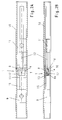
- the closing sequence controller 1 which can be used according to the door arrangement described in FIG. 1, will be described in more detail in the following FIGS. 2 to 8. It is understood that the closing sequence control according to the invention in addition to the features making up the particular features of the present invention, of course, all other known features, such as mechanical or electrical drives, possibly required sensors and control and regulating devices may have to operate a two-leaf door fully automatic or semi-automatic.
- the closing sequence controller 1 initially has a first slider 9 which is connected to the door frame end of the swing arm 6 of the active leaf 4. As already explained, this first slider 9 is slidably mounted in the slide frame 10 mounted in the door frame 7.
- the second slider 11 is connected to the door frame side end of the swing arm 5 of the passive leaf 3. It is also slidably disposed in the sliding guide 10.
- the slider 11 has a trip bar 12 which is fixedly connected to the slider 11.
- the trigger bar 12 in turn has a tip 16 which is engageable with a mounted in the base body 13 locking member 8 and disengaged.
- the trigger bar 12 is inserted into the main body 13 and the tip 16 is preferably bevelled.
- the locking member 8 is always biased in the direction of its blocking position, for which purpose a spring element 8a may be provided.
- a flexurally elastic base body 13 is produced Clamping bracket 17 is attached, which is designed in the manner of a Kragkons.
- the clamping bracket 17 is angled towards the inactive side, there accordingly has a ramp 18, which is provided with a recess, engages through the trigger bar 12 into the interior of the clamping bracket 17.
- the locking member 8 is arranged, which is formed in the example trap as a pinch roller.
- the locking member 8 is biased by means of the spring element 8a, preferably in the form of a helical compression spring, in the direction of its locking or clamping position. Due to the bias, the locking member 8 is pressed onto the ramp 18 and pressed by this with its friction surface 14 in the direction of the associated surface area of the clamping rod 15 which passes through the base body 13 and the clamping bracket 17 and the slider 11 therethrough. In the clamping or locking position, the locking member 8 forms with the clamping rod 15 and the tapered end or the ramp 18 of the clamping bracket 17 an effective pairing.
- the fixed to the slider 11 release rod 12 can cancel this clamping position and interrupt the effective pairing between locking member 8 and clamping rod 15.
- the representation according to FIGS. 2A and 2B represents the closed position of the door leaves 3 and 4 of the door 2.
- both sliders 9 and 11 are in their initial position and the trigger bar 12 pushes the locking member 8 out of its locked position.
- the slider 11 of the passive leaf 3 is in this position, the slider 9 of the active leaf 4 and thus the active leaf 4 itself is free to move. If the active leaf 4 is opened, this can close normally by the closing sequence controller 1, since the trigger bar 12 prevents clamping of the clamping rod 15 by the locking member 8.
- the locking member 8 follows due to the action of the compression spring of the trip bar 12 until the locking member 8 is in its clamping position in which no contact between the trigger bar 12 and locking member 8 is made.
- an L-shaped holder 22 is provided in the sliding guide 10, which is arranged with its longer leg between the sliding guide 10 and the clamping bracket 17.
- the shorter leg of the L-shaped holder 22 is seen from the locking member 8 from behind the clamping bracket 17.
- a thread is provided, in which an adjusting screw 21 is rotatably supported.
- the adjusting screw 21 has at its end remote from the locking member 8 an engagement possibility for an adjusting tool, by means of which the adjusting screw 21 can be rotated.
- a slot 24 is provided for this purpose, the Intervention of a screwdriver allows. Instead, however, a hexagon or the like may be provided.
- the adjusting screw 21 is fixed to the clamp 17.
- the adjusting screw 21 is provided with a lock nut 23, by means of which the adjusting screw 21 can be fixed to the L-shaped holder 22.
- the entire length L of the clamp 17 corresponds to the fedemden length, ie by the fixed length L, it is not possible to influence the release force of the slider 9 of the active leaf. It is different with the adjustable overload protection according to the invention.
- the resilient length L of the clamping bracket 17 can be set arbitrarily within the adjustment range provided, so thus thus also the required disengaging force is adjustable. If the clamp 17 is moved by the adjusting screw 21 to the right, the resilient length L decreases and the release force increases. If the clamp 17 is moved in the opposite direction, it behaves exactly the opposite, the resilient length L increases, which automatically reduces the Ausgurkraft.
- the lock nut 23 the setting of the clamping bracket 17 can be locked so as to ensure a set constant release force.
Landscapes
- Power-Operated Mechanisms For Wings (AREA)
Applications Claiming Priority (1)
| Application Number | Priority Date | Filing Date | Title |
|---|---|---|---|
| DE200510009678 DE102005009678A1 (de) | 2005-02-28 | 2005-02-28 | Schließfolgeregler |
Publications (1)
| Publication Number | Publication Date |
|---|---|
| EP1703061A2 true EP1703061A2 (fr) | 2006-09-20 |
Family
ID=36540256
Family Applications (1)
| Application Number | Title | Priority Date | Filing Date |
|---|---|---|---|
| EP20060001508 Withdrawn EP1703061A2 (fr) | 2005-02-28 | 2006-01-25 | Commande de séquence de fermeture |
Country Status (2)
| Country | Link |
|---|---|
| EP (1) | EP1703061A2 (fr) |
| DE (1) | DE102005009678A1 (fr) |
Cited By (1)
| Publication number | Priority date | Publication date | Assignee | Title |
|---|---|---|---|---|
| AT510683A4 (de) * | 2010-11-23 | 2012-06-15 | Walter Ing Degelsegger | Vorrichtung für das steuern der schliessfolge von zweiflügeligen schwenktüren |
Families Citing this family (1)
| Publication number | Priority date | Publication date | Assignee | Title |
|---|---|---|---|---|
| CN110206431B (zh) * | 2019-07-12 | 2024-08-02 | 广东合和建筑五金制品有限公司 | 一种用于防火门窗温控式自闭器 |
Citations (1)
| Publication number | Priority date | Publication date | Assignee | Title |
|---|---|---|---|---|
| DE3336739C2 (fr) | 1983-10-08 | 1988-01-28 | Dorma Gmbh + Co Kg, 5828 Ennepetal, De |
-
2005
- 2005-02-28 DE DE200510009678 patent/DE102005009678A1/de not_active Withdrawn
-
2006
- 2006-01-25 EP EP20060001508 patent/EP1703061A2/fr not_active Withdrawn
Patent Citations (1)
| Publication number | Priority date | Publication date | Assignee | Title |
|---|---|---|---|---|
| DE3336739C2 (fr) | 1983-10-08 | 1988-01-28 | Dorma Gmbh + Co Kg, 5828 Ennepetal, De |
Cited By (2)
| Publication number | Priority date | Publication date | Assignee | Title |
|---|---|---|---|---|
| AT510683A4 (de) * | 2010-11-23 | 2012-06-15 | Walter Ing Degelsegger | Vorrichtung für das steuern der schliessfolge von zweiflügeligen schwenktüren |
| AT510683B1 (de) * | 2010-11-23 | 2012-06-15 | Walter Ing Degelsegger | Vorrichtung für das steuern der schliessfolge von zweiflügeligen schwenktüren |
Also Published As
| Publication number | Publication date |
|---|---|
| DE102005009678A1 (de) | 2006-08-31 |
Similar Documents
| Publication | Publication Date | Title |
|---|---|---|
| EP1247930B1 (fr) | Dispositif d'arrêt pour chariots guidés dans des rails | |
| AT412411B (de) | Elektromechanische feststellvorrichtung für türflügel mit einem türschliesser | |
| EP2352893B1 (fr) | Unité de blocage pour une fermeture de porte,système de fermeture de porte, utilisation d'une unité de blocage et procédé de blocage d'une porte | |
| DE102008048994B4 (de) | Feststellvorrichtung für einen Flügel einer Tür | |
| DE102012111085B4 (de) | Türöffner | |
| EP2354402A2 (fr) | Verrouillage pour installations de battants | |
| EP3034728B1 (fr) | Dispositif limiteur d'ouverture | |
| EP3420166B1 (fr) | Dispositif anti-relèvement pour un battant à coulissement parallèle se présentant sous forme d'oscillo-battant coulissant ou de battant coulissant | |
| WO2019042836A1 (fr) | Dispositif d'insertion permettant d'insérer une partie mobile d'un meuble ou d'un appareil ménager dans une position finale | |
| EP2843169A1 (fr) | Système de support pour une porte coulissante et porte coulissante | |
| EP0846825B1 (fr) | Dispositif de verrouillage pour un vantail de porte amovible dans un châssis | |
| EP1703061A2 (fr) | Commande de séquence de fermeture | |
| DE10111732A1 (de) | Schliessfolgeregler für eine zweiflügelige Tür | |
| DE102019135814B3 (de) | Verfahren und System zur Begrenzung des Öffnungswinkels eines Tür- und/oder Fensterflügels | |
| DE10107785B4 (de) | Schließfolgeregeler | |
| DE102018202813B3 (de) | Mechanischer Auslöser | |
| EP3625420B1 (fr) | Meuble et procédé de montage d'un élément coulissant sur un corps de meuble | |
| DE10107886B4 (de) | Schließfolgeregler | |
| DE10107888B4 (de) | Schließfolgeregler | |
| EP1233131B1 (fr) | Commande de séquence de fermeture | |
| DE10107884B4 (de) | Schließfolgeregler | |
| EP2626492A2 (fr) | Ferrure à crémone avec un mode d'entrebaillement- et un mode de fermeture et une méthode | |
| DE10205926A1 (de) | Schließfolgeregler | |
| EP2690241B1 (fr) | Armature pour une porte coulissante à fermeture parallèle ou une fenêtre coulissante à fermeture parallèle | |
| DE10107787B4 (de) | Schließfolgeregler |
Legal Events
| Date | Code | Title | Description |
|---|---|---|---|
| PUAI | Public reference made under article 153(3) epc to a published international application that has entered the european phase |
Free format text: ORIGINAL CODE: 0009012 |
|
| AK | Designated contracting states |
Kind code of ref document: A2 Designated state(s): AT BE BG CH CY CZ DE DK EE ES FI FR GB GR HU IE IS IT LI LT LU LV MC NL PL PT RO SE SI SK TR |
|
| AX | Request for extension of the european patent |
Extension state: AL BA HR MK YU |
|
| STAA | Information on the status of an ep patent application or granted ep patent |
Free format text: STATUS: THE APPLICATION HAS BEEN WITHDRAWN |
|
| 18W | Application withdrawn |
Effective date: 20070504 |