EP1233345B1 - Système d'imagerie, programme utilisé pour le contrôle des données d'images d'un tel système, méthode de correction de la distorsion d'images acquises par un tel système et support d'enregistrement des procédures d'une telle méthode - Google Patents
Système d'imagerie, programme utilisé pour le contrôle des données d'images d'un tel système, méthode de correction de la distorsion d'images acquises par un tel système et support d'enregistrement des procédures d'une telle méthode Download PDFInfo
- Publication number
- EP1233345B1 EP1233345B1 EP02250828A EP02250828A EP1233345B1 EP 1233345 B1 EP1233345 B1 EP 1233345B1 EP 02250828 A EP02250828 A EP 02250828A EP 02250828 A EP02250828 A EP 02250828A EP 1233345 B1 EP1233345 B1 EP 1233345B1
- Authority
- EP
- European Patent Office
- Prior art keywords
- image
- image data
- imaging system
- captured image
- buffer memory
- Prior art date
- Legal status (The legal status is an assumption and is not a legal conclusion. Google has not performed a legal analysis and makes no representation as to the accuracy of the status listed.)
- Expired - Lifetime
Links
Images






Classifications
-
- G—PHYSICS
- G02—OPTICS
- G02B—OPTICAL ELEMENTS, SYSTEMS OR APPARATUS
- G02B27/00—Optical systems or apparatus not provided for by any of the groups G02B1/00 - G02B26/00, G02B30/00
- G02B27/0025—Optical systems or apparatus not provided for by any of the groups G02B1/00 - G02B26/00, G02B30/00 for optical correction, e.g. distorsion, aberration
-
- H—ELECTRICITY
- H04—ELECTRIC COMMUNICATION TECHNIQUE
- H04N—PICTORIAL COMMUNICATION, e.g. TELEVISION
- H04N23/00—Cameras or camera modules comprising electronic image sensors; Control thereof
- H04N23/60—Control of cameras or camera modules
- H04N23/698—Control of cameras or camera modules for achieving an enlarged field of view, e.g. panoramic image capture
-
- H—ELECTRICITY
- H04—ELECTRIC COMMUNICATION TECHNIQUE
- H04N—PICTORIAL COMMUNICATION, e.g. TELEVISION
- H04N23/00—Cameras or camera modules comprising electronic image sensors; Control thereof
-
- G—PHYSICS
- G06—COMPUTING OR CALCULATING; COUNTING
- G06T—IMAGE DATA PROCESSING OR GENERATION, IN GENERAL
- G06T5/00—Image enhancement or restoration
- G06T5/80—Geometric correction
-
- H—ELECTRICITY
- H04—ELECTRIC COMMUNICATION TECHNIQUE
- H04N—PICTORIAL COMMUNICATION, e.g. TELEVISION
- H04N5/00—Details of television systems
- H04N5/222—Studio circuitry; Studio devices; Studio equipment
- H04N5/262—Studio circuits, e.g. for mixing, switching-over, change of character of image, other special effects ; Cameras specially adapted for the electronic generation of special effects
- H04N5/2628—Alteration of picture size, shape, position or orientation, e.g. zooming, rotation, rolling, perspective, translation
Definitions
- the present invention relates to: an imaging system capable of capturing a 360-degree field of view image in a single shooting; software used for controlling data representing the captured image; a method for correcting distortion in an image captured by the imaging system; and a recording medium storing procedures for such a method. From the image captured by the imaging system, space geometry, a configuration of an object, etc., can be correctly perceived.
- an imaging system can be preferably used in wide-ranging fields including the field of security for monitoring stores, banks, etc.; the field of on-vehicle use, such as avoidance of automobile collision, and monitoring of the inside of a vehicle; and the field of measuring instruments for use in a visual section of an industrial robot, for example.
- a reflecting mirror having a geometry of one of two sheets of a two-sheeted hyperboloid (hereinafter, referred to as "the first sheet of a two-sheeted hyperboloid") is used as the hyperboloidal mirror for producing a central projection image.
- a lens center of a camera is arranged in a focal position of a geometry of the other one of the two sheets of the two-sheeted hyperboloid (hereinafter, referred to as "the second sheet of a two-sheeted hyperboloid") opposed to the first sheet of the two-sheeted hyperboloid (see, for example, Japanese Laid-Open Patent Publication No. 6-295333).
- US Patent 6,130,783 A discloses an omnidirectional visual sensor using hyperboloidal mirrors.
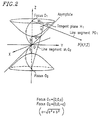
- Figure 2 is a diagram for explaining a two-sheeted hyperboloidal function and its characteristics.
- the imaging system which uses a hyperboloidal mirror having a geometry of the first sheet of a two-sheeted hyperboloid (shown at the top in Figure 2), where a lens center of a camera is arranged in a position of focus O 2 of the second sheet of the two-sheeted hyperboloid (shown at the bottom in Figure 2), when an object is input (captured) as an image, the input image (captured image) is a central projection image.
- One of advantages of the imaging system using such a hyperboloidal mirror is that the central projection image can be readily transformed into an image in any spatial position around the central projection image.
- the lens position for producing the central projection image is limited to one point (focus O 2 ).
- the central projection image is captured by the conventional imaging system under a condition where the focus is not adjusted to be on the entire surface of the hyperboloidal mirror, rather the focus is adjusted to be only on a partial area of the surface of the hyperboloidal mirror.
- the area of the surface of the hyperboloidal mirror on which the lens is focused has, for example, a doughnut-shape, and as such the entire central projection image is not captured.
- an imaging system comprising: a reflecting mirror having a geometry of one of two sheets of a two-sheeted hyperboloid; and an imaging section which includes a light receiving element for receiving light concentrated by an imaging lens having its center located at any position opposing said reflecting mirror on the rotation axis of this reflecting mirror wherein the imaging system includes an image processing section for performing a coordinate transformation on the captured image data characterised in that said image processing section comprises means for acquiring image data of an object inspection drawing so as to produce a perspective transformed image data and means for correcting distortion in the captured image on the basis of the distance between the imaging lens position adapted for the coordinate transformation and the light-receiving surface of said light receiving element and on the basis of said transformed image data.
- a squared inspection drawing is used as the inspection drawing.
- the image processing section includes: means for transforming the captured image data into the perspective transformed image data so as to produce a perspective transformed image; and an operation panel for inputting an instruction to increase or decrease the value regarding the distance between the imaging lens position and the light-receiving surface of the light receiving element.
- the image processing section includes: means for transforming the captured image data into the perspective transformed image data so as to produce a perspective transformed image; and an image recognition section for recognizing whether or not the produced perspective transformed image is distorted by comparing the produced perspective transformed image to an image expected to be obtained when the captured image is a central projection image.
- the image processing section performs coordinate transformation processing according to an instruction signal output by the operation panel.
- the image processing section performs coordinate transformation processing according to an instruction signal output by the image recognition section.
- the image processing section includes: a CPU connected to a bus line; an input buffer memory; a look-up table; an arithmetic processing circuit; and an output buffer memory, wherein: the CPU controls arithmetic processing; the input buffer memory stores captured image data; the look-up table and the arithmetic processing circuit are used for the arithmetic processing; and the output buffer memory includes the image processing section for storing perspective transformed image data.
- the image processing section includes: a CPU connected to a bus line; an input buffer memory; a look-up table; an arithmetic processing circuit; and an output buffer memory, wherein: the CPU controls arithmetic processing; the input buffer memory stores captured image data; the look-up table and the arithmetic processing circuit are used for the arithmetic processing; and the output buffer memory includes the image processing section for storing perspective transformed image data.
- a program used for controlling image data in an imaging system comprising: a computer; a reflecting mirror having a geometry of one of two sheets of a two-sheeted hyperboloid; and an imaging section which includes a light receiving element for receiving light concentrated by an imaging lens having its center located at any position opposing said reflecting mirror on the rotation axis of said reflecting mirror, and the program being adapted to control the computer so as to serve as: a coordinate transformation section for performing coordinate transformation on captured image data wherein the program is characterised in that it is adapted to control the computer so as to capture image data obtained from an object inspection drawing so as to produce perspective transformation image data; the program further adapted to control the computer so as to serve as a correction section for correcting distortion in the captured image on the basis of the distance between the imaging lens position adapted for the coordinate transformation and the light-receiving surface of said light receiving element and on the basis of said transformed image data.
- a method for correcting a captured image in an imaging system comprising: a reflecting mirror having a geometry of one of two sheets of a two-sheeted hyperboloid; and a light receiving element for receiving light concentrated by an imaging lens having its center located at any position opposing said reflecting mirror on the rotation axis of said reflecting mirror, the method characterised by; a first step of storing captured image data obtained from an object inspection drawing in an input buffer memory; a second step of performing coordinate transformation, according to an instruction from a CPU responding to an instruction signal output by an operation panel, on the captured image data stored in the input buffer memory using an arithmetic processing circuit so as to produce perspective transformed image data and storing the perspective transformed image data in an output buffer memory; and a third step of displaying an image produced from the perspective transformed image data stored in the output buffer memory on a monitor, the image being confirmed by an inspector, wherein: when a perspective transformed image obtained by capturing an image of a squared inspection drawing is
- a method for correcting a captured image in an imaging system comprising: a reflecting mirror having a geometry of one of two sheets of a two-sheeted hyperboloid; and a light receiving element for receiving light concentrated by an imaging lens having its center located at any position opposing said reflecting mirror on the rotation axis of said reflecting mirror, the method characterised by; a first step of storing captured image data obtained by capturing an image of an object inspection drawing in an input buffer memory; a second step of performing coordinate transformation, according to an instruction from a CPU responding to an instruction signal output by an image recognition section, on the captured image data stored in the input buffer memory using an arithmetic processing circuit so as to produce perspective transformed image data and storing the perspective transformed image data in an output buffer memory; and a third step for comparing the perspective transformed image data stored in the output buffer memory to expected image data obtained when a captured image is a central projection image by using the image recognition section, wherein: when a perspective transformed image obtained by
- an imaging system for transforming captured image data into perspective transformed image data using a value regarding a distance between a light-receiving surface of a light receiving element and an imaging lens position used when a perspective transformed image obtained by capturing an image of a prescribed inspection drawing is not determined to be distorted by a method for correcting distortion of a captured image.
- an imaging system for transforming captured image data into perspective transformed image data using a value regarding a distance between a light-receiving surface of a light receiving element and an imaging lens position used when a perspective transformed image obtained by capturing an image of a prescribed inspection drawing is not determined to be distorted by a method for correcting distortion of a captured image.
- a recording medium storing procedures for a method for correcting distortion of a captured image according to claim 11.
- a recording medium storing procedures for a method for correcting distortion of a captured image according to claim 12.
- a lens position of a camera is shifted from a focus position (i.e., a position under such conditions as to satisfy the requirements for central projection in geometric optics) of the second sheet of a two-sheeted hyperboloidal mirror so as to be away from the hyperboloidal mirror.
- a focus position i.e., a position under such conditions as to satisfy the requirements for central projection in geometric optics
- an entire virtual image reflected in the hyperboloidal mirror is placed within the depth of focus of a lens, and thus it is possible to focus the lens onto an entire surface of the hyperboloidal mirror.
- the lens position is shifted from the focus position of the second sheet of the two-sheeted hyperboloidal mirror, it is possible to correct distortion of a captured image (input image) and transform such an image into a central projection image.
- the lens is preadjusted in a prescribed position.
- a prescribed inspection drawing e.g., a squared inspection drawing
- coordinate transformation is performed on data representing the captured image so as to produce perspective transformed image data.
- F value a value regarding a distance between the lens position adapted for coordinate transformation and a light-receiving surface of a camera (imaging section) is increased or decreased.
- a device In order to correct distortion in a captured image, it is applicable to a device (correction section) including: an image processing section for transforming data representing the captured image into perspective transformed image data so as to produce a perspective transformed image, and a section provided with an operation panel for inputting an amount of distortion to be corrected when the produced perspective transformed image is distorted.
- step 4 of the method shown in Figure 9, which will be described in an example below whether or not the type of the distortion in the image is barrel distortion (distorted along a "+" direction) is determined.
- a key to decrease the F value is operated.
- a control signal to decrease the F value is transmitted to the image processing section and the procedure returns to step 2.
- arithmetic processing is performed again using Expressions (1) and (2) described above, so that the perspective transformed image is displayed again.
- step 3 whether or not the image is distorted is confirmed again.
- the procedure returns to step 4.
- step 4 when the type of the distortion in the image is determined to be pincushion distortion (distorted along a "-" direction) at step 4, a key to increase the F value is operated at step 5.
- a control signal to increase the F value is transmitted to the image processing section and the procedure returns to step 2.
- arithmetic processing is performed again using Expressions (1) and (2), so that the perspective transformed image is displayed again.
- step 3 whether or not the image is distorted is confirmed again.
- the procedure returns to step 4.
- a device including: an image processing section for transforming data representing the captured image into perspective transformed image data so as to produce a perspective transformed image, and an image recognition section for recognizing whether or not the perspective transformed image is distorted by comparing the produced perspective transformed image to an image expected to be obtained when the captured image is a central projection image. Therefore, at the step of correcting the F value as described above, by using the image recognition section, it is also possible to automatically determine whether or not the image is distorted and the distorted direction (i.e., whether or not the type of the distortion is the barrel distortion), although, in a conventional system, such determination is manually carried out.
- the image recognition section determines whether or not the image is distorted and also determines an amount of the distortion.
- the image recognition section automatically transmits a signal representing a correction value, which corresponds to the amount of the distortion, to the image processing section so as to cause the image processing section to perform arithmetic processing again based on the correction value. As a result, an image corresponding to the correction value is displayed.
- the image recognition section again, automatically repeats the operation of determining whether or not the image is distorted and determining an amount of the distortion. Such operation can be repeated until the distortion is reduced to a prescribed value or lower.
- the image processing section it is applicable to a device including: a CPU for controlling arithmetic processing operations; an input buffer memory for storing captured image data; an LUT (Look-Up Table) used for arithmetic processing; an arithmetic processing circuit; and an output buffer memory for storing perspective transformed image data.
- these components are connected to a bus line.
- a program allows a computer to serve as: a coordinate transformation section for performing coordinate transformation on image data obtained by capturing an image of a prescribed inspection drawing so as to produce perspective transformed image data; and a distortion correction section for performing the coordinate transformation on the produced perspective transformed image data by increasing or decreasing a value regarding a distance between a lens position adapted for the coordinate transformation and a light receiving surface according to the type of the distortion when a perspective transformed image produced from the perspective transformed image data is distorted, so that it is possible to automatically perform correction processing.
- a prescribed inspection drawing e.g., a squared inspection drawing
- the arithmetic processing circuit performs the coordinate transformation on the captured image data according to an instruction from the CPU, which is based on an operation signal from the operation panel or the image recognition section, so that perspective transformed image data is produced.
- the perspective transformed image data is stored in the output buffer memory of the image processing section and is output to a monitor according to an instruction from the CPU, which is based on an operation signal from the operation panel or the image recognition section.
- a value (F value) regarding a distance between a lens position and a light-receiving surface, which is input to the operation panel, is increased or decreased. Such operation is repeated so as to correct the distortion in the captured image, so the captured image can be transformed into a central projection image.
- the invention described herein makes possible the advantages of providing: an imaging system in which a lens position for producing a central projection image is not limited to one point and the central projection image is produced under a condition where a lens is focused onto an entire surface of a hyperboloidal mirror; software used for controlling data representing the produced image; a method for correcting distortion in an image captured by the imaging system; and a recording medium storing procedures for such a method.
- Figure 1 is a diagram for explaining a basic structure and geometric positional relationship among components of an imaging system 100 according to an example of the present invention.
- the imaging system 100 includes a hyperboloidal mirror 1 , an imaging section 2 (including an imaging lens 3 and a light-receiving element 4 ), an image processing section 5 , and a TV monitor 6 .
- the hyperboloidal mirror 1 is a reflecting mirror having a geometry of the first sheet of a two-sheeted hyperboloid.
- Figure 2 illustrates a two-sheeted hyperboloid when graphically representing Expression (3).
- a, b and c are referred to as mirror constants.
- a point of intersection between line segment PO 1 extending between focus O 1 and an arbitrary point P(X,Y,Z) on the outside of the hyperboloid and the hyperboloid satisfying Expression (3) is referred to by point M 1 .
- a ray of light represented by line segment PO 1 is incident on tangent plane H 1 of the hyperboloid which is in contact with line segment PO 1 at Point M 1 .
- An incident angle ( ⁇ ) formed by line segment PO 1 with tangent plane H 1 is equivalent to a reflecting angle ( ⁇ ) at which a ray of light represented by line segment M 1 O 2 exits the hyperboloid.
- Line segment M 1 O 2 always passes through focus O 2 of the second sheet of the two-sheeted hyperboloid.
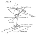
- Figure 3 is a diagram for explaining a lens position of the imaging system which satisfies the requirements for the central projection. It is most important to arrange the center of the imaging lens in the position of focus O 2 of the second sheet of the two-sheeted hyperboloid which forms a counterpart to focus O 1 of the hyperboloidal mirror.
- An input image (captured image) obtained via a light-receiving element having a light-receiving surface at a position at distance F from the lens center is called a central projection image.
- Expressions (1) and (2) are obtained, based on the positional relationship among elements shown in Figures 2 and 3 , using the following Expressions (4), (5), and (6):
- Z Rtan ⁇ +c, 1f
- An input image which satisfies the requirements for the central projection is an image simultaneously satisfying Expressions (4) through (6).
- Expressions (4) through (6) the input image can be readily transformed to a perspective image which can be seen from focus O 1 .
- Such transformation is called a perspective transformation.
- An image (perspective image) produced by the perspective transformation is an image which can be usually seen by the human eye. In such an image, a three-dimensional space is projected onto a two-dimensional space.
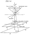
- Distance F is a vertical distance from the lens center to an imaging surface of the light-receiving element.
- Angle a is an angle formed by a horizontal plane including a focus of the mirror with line segment PO 1 .
- Angle ⁇ is a zenithal angle when an incident point on the mirror is seen from the center of an imaging mechanism. The input image is obtained by capturing a virtual image reflected in the mirror by the lens.
- Figure 4 is a cross-sectional view for explaining a lens position of the imaging system which satisfies the requirements for central projection.
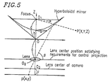
- Figure 5 is a cross-sectional view for explaining a lens position of the imaging system which does not satisfy the requirements for central projection.
- Figures 4 and 5 differ from each other in that an imaging lens shown in Figure 5 is shifted from position O 2 which essentially satisfies the central projection to position O 3 .
- the position of the imaging lens shown in Figure 5 may be shifted to a hyperboloidal mirror side or an opposing side.
- Figure 6 is a schematic diagram for explaining an imaging mechanism and a magnification of an image when a single lens is used.
- object A is a virtual image reflected in the hyperboloidal mirror.
- Figure 6 shows lens positions O 2 (A) and O 3 (A), focal distance f of the lens, distance S 2 from lens position O 2 (A) to object A, and distance S 3 from lens position O 3 (A) to object A.
- each of lengths h 2 and h 3 of the images represents a distance from an optical axis to the vertex of the image (i.e., a distance from the Z-axis to the vertex of the image), and thus can be represented by ⁇ (x 2 +y 2 ) (the radius) in Expression (6).
- a position coordinate ⁇ (x 2 +y 2 ) of the input image is different from a position coordinate of the input image obtained when the lens is in the position satisfying the requirements for central projection, only by a constant multiple.
- distance F which is a distance from the lens position which does not satisfy the requirements for central projection to the imaging surface
- distance F 0 which is a distance from the lens position satisfying the requirements for central projection to the imaging surface
- the F value can be optionally selected depending on a change in an optical system while the F value represents a fixed distance (i.e., F 0 as described above) from the optical system of the lens to an imaging surface in conventional technologies.
- FIG. 7A illustrates a top view of the squared inspection drawing.
- Figure 7B illustrates a perspective view of the squared inspection drawing.
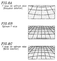
- Figures 8A, 8B , and 8C respectively, illustrate perspective images of the squared inspection drawing.
- Figure 8A illustrates an image (with pincushion distortion) of the inspection drawing, where the F value ⁇ an optimum value (e.g., the lens position is shifted by about 0.4 mm to about 0.7 mm from the lens position satisfying the requirements for central projection to the hyperboloidal mirror side).
- Figure 8C illustrates an image (with barrel distortion) of the inspection drawing, where the F value > an optimum value (e.g., the lens position is shifted by about 0.4 mm to about 0.7 mm from the lens position satisfying the requirements for central projection to the light-receiving element side).
- the imaging system Prior to setting the F value, the imaging system captures an image of the inspection drawing.
- the F value is adjusted such that, when the perspective transformation is performed on the captured image so as to produce a perspective image, the perspective image includes accurate square subdivisions (i.e., the image illustrated in Figure 8B is obtained).
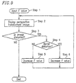
- Figure 9 is a flowchart for explaining a procedure for changing the F value.
- a squared inspection drawing as described above is created and an image of the squared inspection drawing is captured by the imaging system prior to setting of the F value.
- distance F from a principal point of a lens prior to setting of the F value to an imaging surface is input to an image processing section of the imaging system.
- distance F may be input to the image processing section by an operator using an operation panel or a distance preset by software (program) may be input to an arithmetic processing circuit in the image processing section.
- step 2 a perspective transformed image of an inspection drawing is displayed.
- step 3 whether or not the image is distorted, that is, whether or not square subdivisions are accurately displayed is determined.
- step 4 whether or not the type of the distortion is barrel distortion is determined.
- the F value is increased.
- the F value is decreased.
- Steps 2 through 4 and steps 5 or 6 are repeated so as to fix the F value for displaying the square subdivisions with the greatest possible accuracy.
- a dappled inspection drawing including staggered patterns of different shades of color
- Other patterns can be used so long as straight lines along horizontal and vertical directions can be clearly distinguished.
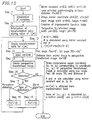
- Figure 10 is a flow chart for explaining a detailed procedure for changing an F value.
- the variables are initialized.
- the initialized variables include mirror constants, a distance between a principal point of a lens and an imaging surface (hereinafter, referred to as a "lens principal point-imaging surface distance"), a center coordinate of a perspective transformed image, width and height of an input image, and a trigonometric function table (these are included in a look-up table, hereinafter referred to as an "LUT", and are required to be initialized since they are recalculated when the F value is changed).
- the initialized variables also include width and height of a perspective transformed image, etc.
- the initialization of these variables can be automatically performed by software (program).
- the trigonometric function table is also created.
- a transformation table storing values for r[ ⁇ ] (r represents a distance from an object to the center of an image plane, and a represents a tilt angle) is initialized.
- the transformation table for r[ ⁇ ] is compiled.
- variables such as a pan angle, a tilt angle ( ⁇ ), and a distance d from a mirror focus to a perspective transformed image.
- a perspective transformed image is created.
- a size of an image plane of a CCD camera can be represented by W ⁇ H.
- the center coordinate can be represented by (cX,cY).
- a size of a perspective transformed screen assumed to be in a three-dimensional space can be represented by phxpw.
- a coordinate on a CCD screen corresponding to each pixel on the assumed screen is calculated using Expression (1) and (2).
- a rotation angle about the coordinate axis z is the pan angle.
- a rotation angle ⁇ (a rotation angle about the z-axis shown in Figure 3) and an angle ⁇ are calculated using the mirror constants tx, ty, and tz.
- the angle ⁇ can be calculated using Expressions (5) and (6).
- the rotation angle ⁇ can be obtained by tan -1 (y/x).
- step 16 whether or not the image is distorted is determined. When the image is not distorted, the processing ends.
- step 17 whether the type of the distortion is barrel distortion or pincushion distortion is determined.
- the F value is increased.
- the F value is decreased.
- the adjustment processing of the F value in this example can be performed using, for example, an image processing section and an operation panel connected thereto, as illustrated in Figure 11 .
- FIG 11 is a block diagram illustrating a structure of an image processing section 5 according to the present invention.
- the image processing section 5 includes an input buffer memory 8 , a CPU 9 , an LUT 10 , an arithmetic logic circuit 11 , an output buffer memory 12 , a bus line 13 , and an operation panel 14 .
- Image data representing an image of an inspection drawing captured by an imaging system is stored in the input buffer memory 8 , and thereafter, according to an instruction from the CPU 9 which is based on an operation signal from the operation panel 14 , coordinate transformation is performed on the image data by the arithmetic logic circuit 11 based on data stored in the LUT 10 .
- the LUT 10 has the transformation table for r[ ⁇ ] stored therein.
- Figure 12 illustrates an example of data organization in the transformation table for r[ ⁇ ] stored in the LUT 10 .
- the data representing perspective transformed image produced by the coordinate transformation is input to the output buffer memory 12 and then, the perspective transformed image is displayed on the monitor according to the instruction by the CPU 9.
- the operator confirms whether or not the image displayed on the monitor is distorted.
- whether the type of the distortion is barrel distortion (see Figure 8C ) or pincushion distortion (see Figure 8A ) is determined.
- the operator operates the operation panel so as to increase or decrease the F value according to the type of distortion.
- the operation panel when the distortion is pincushion distortion, by operating the operation panel so as to increase the F value, the operation panel transmits an operation signal to the CPU 9 .
- the operation signal is further transmitted via the bus line from the CPU 9 to the arithmetic logic circuit 11 .
- the F value is increased in the arithmetic logic circuit 11 and the coordinate transformation is performed on the image data.
- Data representing the perspective transformation image produced after the F value has been increased is input to the output buffer memory 12 .
- the image is output to the monitor according to the instruction by the CPU 9 .
- the operator confirms the decrease in the distortion in the image on the monitor. This operation is repeated until the distortion is minimized.
- the imaging system can perform the coordinate transformation on captured image data based on the optimized F value, so that the perspective image data is obtained.
- the operation panel may not be provided to the imaging system.
- a central projection image substantially free from distortion can be obtained.
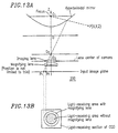
- Figures 13A and 13B are diagrams for explaining an imaging system 200 incorporating a magnifying lens.
- the present invention can increase a distance from an image reflected in a hyperboloidal mirror to a lens, and thus it is possible to eliminate a need for a specially-processed lens and to obtain a satisfactory image using an ordinary lens. Moreover, by increasing the distance, it is possible to eliminate a need for adjusting the aperture diaphragm so as to reduce an effective aperture of the lens, thereby extremely lowering limits of imaging requirements, so that adjustments are facilitated.
- the present invention can readily satisfy requirements for central projection by adjusting a lens such that the lens is initially in a prescribed position, and then changing the F value for image processing, the optical adjustment step can be shortened.
- the adjustment accuracy for producing the central projection image can be improved.
Landscapes
- Engineering & Computer Science (AREA)
- Physics & Mathematics (AREA)
- Multimedia (AREA)
- Signal Processing (AREA)
- General Physics & Mathematics (AREA)
- Optics & Photonics (AREA)
- Theoretical Computer Science (AREA)
- Image Processing (AREA)
- Studio Devices (AREA)
- Lenses (AREA)
Claims (16)
- Système d'imagerie comprenant :dans lequel le système d'imagerie comprend une section de traitement d'image (5) pour effectuer une transformation de coordonnées sur les données d'image capturée, caractérisé en ce que ladite section de traitement d'image (5) comprend un moyen pour acquérir des données d'image d'un dessin d'examen d'objet afin de produire des données d'image transformée en perspective et un moyen pour corriger une déformation dans l'image capturée sur la base de la distance entre la position de la lentille d'imagerie (3) conçue pour la transformation de coordonnées et la surface de réception de lumière dudit élément de réception de lumière (4) et sur la base desdites données d'image transformée.un miroir réfléchissant (1) ayant une géométrie de l'un des deux plans d'un hyperboloïde à deux plans ; etune section d'imagerie (2) qui comprend un élément de réception de lumière (4) pour recevoir de la lumière concentrée par une lentille d'imagerie (3) ayant son centre situé à n'importe quelle position faisant face audit miroir réfléchissant (1) sur l'axe de rotation de ce miroir réfléchissant (1),
- Système d'imagerie selon la revendication 1, dans lequel la transformation de coordonnées est effectuée sur les données d'image capturée afin de produire les données d'image transformée en perspective en utilisant l'expression suivante :
- Système d'imagerie selon la revendication 1, dans lequel un dessin d'examen carré est utilisé en tant que dessin d'examen.
- Système d'imagerie selon la revendication 1, dans lequel la section de traitement d'image comprend :un moyen pour transformer les données d'image capturée en données d'image transformée en perspective afin de produire une image transformée en perspective ; etun panneau de mise en oeuvre pour entrer une instruction pour augmenter ou diminuer la valeur concernant la distance entre la position de lentille d'imagerie et la surface de réception de lumière de l'élément de réception de lumière.
- Système d'imagerie selon la revendication 1, dans lequel la section de traitement d'image comprend :un moyen pour transformer les données d'image capturée en données d'image transformée en perspective afin de produire une image transformée en perspective ; etune section de reconnaissance d'image pour reconnaítre si vraiment l'image transformée en perspective produite est déformée en comparant l'image transformée en perspective produite à une image que l'on s'attend à obtenir quand l'image capturée est une image de projection centrale.
- Système d'imagerie selon la revendication 4, dans lequel la section de traitement d'image effectue un traitement de transformation de coordonnées selon un signal d'instruction sorti par le panneau de mise en oeuvre.
- Système d'imagerie selon la revendication 5, dans lequel la section de traitement d'image effectue un traitement de transformation de coordonnées selon un signal d'instruction sorti par la section de reconnaissance d'image.
- Système d'imagerie selon la revendication 4, dans lequel la section de traitement d'image comprend :dans lequel :une CPU reliée à une ligne de bus ;une mémoire tampon d'entrée ;une table de consultation ;un circuit de traitement arithmétique ; etune mémoire tampon de sortie,la CPU commande le traitement arithmétique ;la mémoire tampon d'entrée stocke les données d'image capturée ;la table de consultation et le circuit de traitement arithmétique sont utilisés pour le traitement arithmétique ; etla mémoire tampon de sortie comprend la section de traitement d'image pour stocker les données d'image transformée en perspective.
- Système d'imagerie selon la revendication 5, dans lequel la section de traitement d'image comprend :dans lequel :une CPU reliée à une ligne de bus ;une mémoire tampon d'entrée ;une table de consultation ;un circuit de traitement arithmétique ; etune mémoire tampon de sortie,la CPU commande le traitement arithmétique ;la mémoire tampon d'entrée stocke les données d'image capturée ;la table de consultation et le circuit de traitement arithmétique sont utilisés pour le traitement arithmétique ; etla mémoire tampon de sortie comprend la section de traitement d'image pour stocker les données d'image transformée en perspective.
- Programme utilisé pour commander des données d'image dans un système d'imagerie, dans lequel ledit système d'imagerie comprend :caractérisé en ce qu'il est conçu pour commander l'ordinateur afin de capturer des données d'image obtenues à partir d'un dessin d'examen d'objet afin de produire des données d'image de transformation en perspective ; le programme étant de plus conçu pour commander l'ordinateur afin de servir de section de correction pour corriger la déformation de l'image capturée sur la base de la distance entre la position de la lentille d'imagerie (3) conçue pour la transformation de coordonnée et la surface de réception de lumière dudit élément de réception de lumière (4) et sur la base desdites données d'image transformée.un ordinateur ;un miroir réfléchissant (1) ayant une géométrie de l'un des deux plans d'un hyperboloïde à deux plans ; etune section d'imagerie (2) qui comprend un élément de réception de lumière (4) pour recevoir de la lumière concentrée par une lentille d'imagerie (3) ayant son centre situé à n'importe quelle position faisant face audit miroir réfléchissant (1) sur l'axe de rotation dudit miroir réfléchissant (1), etle programme étant conçu pour commander l'ordinateur afin de servir de :section de transformation de coordonnées pour effectuer une transformation de coordonnées sur des données d'image capturée, dans lequel le programme est
- Procédé de correction d'une image capturée dans un système d'imagerie, dans lequel le système d'imagerie comprend :dans lequel :un miroir réfléchissant (1) ayant une géométrie de l'un des deux plans d'un hyperboloïde à deux plans ; etun élément de réception de lumière (4) pour recevoir de la lumière concentrée par une lentille d'imagerie (3) ayant son centre situé à n'importe quelle position faisant face audit miroir réfléchissant (1) sur l'axe de rotation dudit miroir réfléchissant (1),le procédé étant caractérisé par :une première étape de stockage de données d'image capturée obtenues à partir d'un dessin d'examen d'objet dans une mémoire tampon d'entrée ;une deuxième étape d'exécution d'une transformation de coordonnées, selon une instruction en provenance d'une CPU répondant à un signal d'instruction sorti par un panneau de mise en oeuvre, sur les données d'image capturée stockées dans la mémoire tampon d'entrée en utilisant un circuit de traitement arithmétique afin de produire des données d'image transformée en perspective et de stockage des données d'image transformée en perspective dans une mémoire tampon de sortie ; etune troisième étape d'affichage d'une image produite à partir des données d'image transformée en perspective stockées dans la mémoire tampon de sortie sur un écran de contrôle (6), l'image étant confirmée par un inspecteur,quand une image transformée en perspective obtenue en capturant une image d'un dessin d'examen carré est déterminée comme étant déformée à la troisième étape, l'inspecteur entre dans le panneau de mise en oeuvre une instruction pour augmenter ou diminuer la distance entre la position de lentille d'imagerie et la surface de réception de lumière de l'élément de réception de lumière (4) de sorte que le panneau de mise en oeuvre sort un signal d'instruction pour changer la valeur de ladite distance entre la position de lentille d'imagerie et la surface de réception de lumière de l'élément de réception de lumière (4) ; etsur la base desdites données d'image transformée ; etles première à troisième étapes sont répétées.
- Procédé de correction d'une image capturée dans un système d'imagerie, dans lequel ledit système d'imagerie comprend :le procédé étant caractérisé par :un miroir réfléchissant (1) ayant une géométrie de l'un des deux plans d'un hyperboloïde à deux plans ; etun élément de réception de lumière (4) pour recevoir de la lumière concentrée par une lentille d'imagerie (3) ayant son centre situé à n'importe quelle position faisant face audit miroir réfléchissant (1) sur l'axe de rotation dudit miroir réfléchissant (1),dans lequel :une première étape de stockage de données d'image capturée obtenues en capturant une image d'un dessin d'examen d'objet dans une mémoire tampon d'entrée ;une deuxième étape d'exécution d'une transformation de coordonnées, selon une instruction en provenance d'une CPU répondant à un signal d'instruction sorti par une section de reconnaissance d'image, sur les données d'image capturée stockées dans la mémoire tampon d'entrée en utilisant un circuit de traitement arithmétique afin de produire des données d'image transformée en perspective et de stockage des données d'image transformée en perspective dans une mémoire tampon de sortie ; etune troisième étape pour comparer les données d'image transformée en perspective stockées dans la mémoire tampon de sortie à des données d'image attendue obtenues quand une image capturée est une image de projection centrale en utilisant la section de reconnaissance d'image,quand une image transformée en perspective obtenue en capturant une image d'un dessin d'examen carré est déterminée comme étant déformée à la troisième étape, la section de reconnaissance d'image sort le signal d'instruction afin de changer la distance entre la position de la lentille d'imagerie (3) et la surface de réception de lumière de l'élément de réception de lumière (4) ; et sur la base desdites données d'image transformée ; etles première à troisième étapes sont répétées.
- Système d'imagerie pour transformer des données d'image capturée en données d'image transformée en perspective en utilisant une valeur concernant une distance entre une surface de réception de lumière d'un élément de réception de lumière et une position de lentille d'imagerie utilisée quand une image transformée en perspective obtenue en capturant une image d'un dessin d'examen prédéterminé n'est pas déterminée comme étant déformée par un procédé de correction de déformation d'une image capturée selon la revendication 11.
- Système d'imagerie pour transformer des données d'image capturée en données d'image transformée en perspective en utilisant une valeur concernant une distance entre une surface de réception de lumière d'un élément de réception de lumière et une position de lentille d'imagerie utilisée quand une image transformée en perspective obtenue en capturant une image d'un dessin d'examen prédéterminé n'est pas déterminée comme étant déformée par un procédé de correction de déformation d'une image capturée selon la revendication 12.
- Support d'enregistrement stockant des procédures pour un procédé de correction de déformation d'une image capturée selon la revendication 11.
- Support d'enregistrement stockant des procédures pour un procédé de correction de déformation d'une image capturée selon la revendication 12.
Applications Claiming Priority (2)
| Application Number | Priority Date | Filing Date | Title |
|---|---|---|---|
| JP2001034691 | 2001-02-09 | ||
| JP2001034691A JP3804916B2 (ja) | 2001-02-09 | 2001-02-09 | 撮像システムとその画像データ制御に用いられるプログラムおよびその撮像システムにおける撮像画像の歪み補正方法とその手順を記憶させた記憶媒体 |
Publications (2)
| Publication Number | Publication Date |
|---|---|
| EP1233345A1 EP1233345A1 (fr) | 2002-08-21 |
| EP1233345B1 true EP1233345B1 (fr) | 2004-11-10 |
Family
ID=18898248
Family Applications (1)
| Application Number | Title | Priority Date | Filing Date |
|---|---|---|---|
| EP02250828A Expired - Lifetime EP1233345B1 (fr) | 2001-02-09 | 2002-02-07 | Système d'imagerie, programme utilisé pour le contrôle des données d'images d'un tel système, méthode de correction de la distorsion d'images acquises par un tel système et support d'enregistrement des procédures d'une telle méthode |
Country Status (6)
| Country | Link |
|---|---|
| US (1) | US7058235B2 (fr) |
| EP (1) | EP1233345B1 (fr) |
| JP (1) | JP3804916B2 (fr) |
| KR (1) | KR100481399B1 (fr) |
| DE (1) | DE60201849T2 (fr) |
| TW (1) | TW542936B (fr) |
Families Citing this family (22)
| Publication number | Priority date | Publication date | Assignee | Title |
|---|---|---|---|---|
| JP2002196438A (ja) * | 2000-10-20 | 2002-07-12 | Matsushita Electric Ind Co Ltd | 広角撮像装置 |
| WO2002078346A1 (fr) * | 2001-03-05 | 2002-10-03 | Siemens Aktiengesellschaft | Procede et dispositif pour corriger une image, en particulier pour systemes de protection de passagers |
| US6744569B2 (en) * | 2001-06-19 | 2004-06-01 | Genex Technologies, Inc | Method and apparatus for omnidirectional three dimensional imaging |
| NZ539632A (en) * | 2002-10-22 | 2008-01-31 | Artoolworks | Tracking a surface in a 3-dimensional scene using natural visual features of the surface |
| US7550701B2 (en) * | 2003-02-25 | 2009-06-23 | Omnivision Cdm Optics, Inc. | Non-linear wavefront coding systems and methods |
| US7059733B2 (en) * | 2003-03-18 | 2006-06-13 | Hitachi, Ltd. | Display apparatus |
| WO2004090581A2 (fr) * | 2003-03-31 | 2004-10-21 | Cdm Optics, Inc. | Systemes et procedes pour reduire au minimum des effets aberrants dans des systemes d'imagerie |
| JP4095491B2 (ja) * | 2003-05-19 | 2008-06-04 | 本田技研工業株式会社 | 距離測定装置、距離測定方法、及び距離測定プログラム |
| US20050058360A1 (en) * | 2003-09-12 | 2005-03-17 | Thomas Berkey | Imaging system and method for displaying and/or recording undistorted wide-angle image data |
| US7536053B2 (en) * | 2004-10-27 | 2009-05-19 | Quality Vision International, Inc. | Method and apparatus for the correction of nonlinear field of view distortion of a digital imaging system |
| US7990412B2 (en) * | 2004-11-01 | 2011-08-02 | Hewlett-Packard Development Company, L.P. | Systems and methods for correcting image perspective |
| EP1808255A1 (fr) | 2006-01-11 | 2007-07-18 | Corus Aluminium Walzprodukte GmbH | Procédé de fabrication d'un assemblage brasé. |
| JP4104631B2 (ja) * | 2006-03-27 | 2008-06-18 | 三洋電機株式会社 | 運転支援装置 |
| IT1378233B1 (it) * | 2006-08-17 | 2010-07-30 | Netnoe S R L | Metodo di acquisizione, elaborazione e presentazione di immagini e sistema multimediale di navigazione abbinato a tale metodo |
| US9471934B2 (en) * | 2011-02-25 | 2016-10-18 | Nokia Technologies Oy | Method and apparatus for feature-based presentation of content |
| US8630446B2 (en) * | 2011-03-31 | 2014-01-14 | Mitsubishi Electronic Research Laboratories, Inc | Method and system for determining projections in non-central catadioptric optical systems |
| US9250510B2 (en) * | 2012-02-15 | 2016-02-02 | City University Of Hong Kong | Panoramic stereo catadioptric imaging |
| US8798451B1 (en) * | 2013-06-15 | 2014-08-05 | Gyeongil Kweon | Methods of obtaining panoramic images using rotationally symmetric wide-angle lenses and devices thereof |
| KR102489794B1 (ko) | 2014-09-15 | 2023-01-18 | 리모트리얼리티 코포레이션 | 컴팩트 파노라마 카메라: 광학 시스템, 장치, 이미지 형성 방법 |
| CN111986097B (zh) * | 2019-05-24 | 2024-02-09 | 北京小米移动软件有限公司 | 图像处理方法及装置 |
| JP7134925B2 (ja) * | 2019-07-05 | 2022-09-12 | 株式会社日立製作所 | ステレオカメラ |
| CN113593019A (zh) * | 2021-08-09 | 2021-11-02 | 北京金恒博远科技股份有限公司 | 一种物体结构变化展示方法、装置及电子设备 |
Family Cites Families (19)
| Publication number | Priority date | Publication date | Assignee | Title |
|---|---|---|---|---|
| US5185667A (en) * | 1991-05-13 | 1993-02-09 | Telerobotics International, Inc. | Omniview motionless camera orientation system |
| US5528194A (en) * | 1991-05-13 | 1996-06-18 | Sony Corporation | Apparatus and method for performing geometric transformations on an input image |
| JP2939087B2 (ja) * | 1993-04-07 | 1999-08-25 | シャープ株式会社 | 全方位視覚系 |
| EP0720125B1 (fr) * | 1994-12-29 | 2002-05-08 | Koninklijke Philips Electronics N.V. | Dispositif de formation d'image et procédé pour effectuer des corrections de distorsions optiques géométriques dans une image |
| JPH0916755A (ja) | 1995-06-30 | 1997-01-17 | Kitakiyuushiyuu Techno Center:Kk | 管内検査用画像装置 |
| JP3950188B2 (ja) * | 1996-02-27 | 2007-07-25 | 株式会社リコー | 画像歪み補正用パラメータ決定方法及び撮像装置 |
| US6118474A (en) * | 1996-05-10 | 2000-09-12 | The Trustees Of Columbia University In The City Of New York | Omnidirectional imaging apparatus |
| US5760826A (en) * | 1996-05-10 | 1998-06-02 | The Trustees Of Columbia University | Omnidirectional imaging apparatus |
| US6624847B1 (en) * | 1996-12-17 | 2003-09-23 | Nature Technology Co., Ltd. | Imaging system |
| KR100231339B1 (ko) * | 1997-07-07 | 1999-11-15 | 류정열 | 자동차의 가솔린 엔진 |
| JP3075345B2 (ja) * | 1997-07-28 | 2000-08-14 | 日本電気株式会社 | 皮膚紋様特徴抽出装置 |
| JP3523783B2 (ja) * | 1998-05-14 | 2004-04-26 | 康史 八木 | 全方位視角センサ |
| US6304285B1 (en) * | 1998-06-16 | 2001-10-16 | Zheng Jason Geng | Method and apparatus for omnidirectional imaging |
| CN1352754A (zh) * | 1999-01-04 | 2002-06-05 | 塞克维森技术公司 | 全景成象装置 |
| JP3420734B2 (ja) * | 1999-03-12 | 2003-06-30 | 東京都下水道サービス株式会社 | 管渠内面画像の処理方法 |
| JP3649621B2 (ja) * | 1999-04-09 | 2005-05-18 | シャープ株式会社 | 光通信装置 |
| KR100330345B1 (ko) * | 1999-09-20 | 2002-04-01 | 김선태 | 광선 반사면 및 굴절면에 사용하는 구상면이 있는 렌즈 |
| US6816625B2 (en) * | 2000-08-16 | 2004-11-09 | Lewis Jr Clarence A | Distortion free image capture system and method |
| JP4713023B2 (ja) | 2001-07-11 | 2011-06-29 | ノリタケ伊勢電子株式会社 | 蛍光表示管 |
-
2001
- 2001-02-09 JP JP2001034691A patent/JP3804916B2/ja not_active Expired - Fee Related
-
2002
- 2002-02-07 EP EP02250828A patent/EP1233345B1/fr not_active Expired - Lifetime
- 2002-02-07 DE DE60201849T patent/DE60201849T2/de not_active Expired - Lifetime
- 2002-02-08 US US10/071,853 patent/US7058235B2/en not_active Expired - Fee Related
- 2002-02-08 KR KR10-2002-0007459A patent/KR100481399B1/ko not_active Expired - Fee Related
- 2002-02-08 TW TW091102408A patent/TW542936B/zh not_active IP Right Cessation
Also Published As
| Publication number | Publication date |
|---|---|
| KR20020066219A (ko) | 2002-08-14 |
| US7058235B2 (en) | 2006-06-06 |
| JP3804916B2 (ja) | 2006-08-02 |
| JP2002236918A (ja) | 2002-08-23 |
| US20020141636A1 (en) | 2002-10-03 |
| DE60201849D1 (de) | 2004-12-16 |
| DE60201849T2 (de) | 2005-11-03 |
| TW542936B (en) | 2003-07-21 |
| KR100481399B1 (ko) | 2005-04-08 |
| EP1233345A1 (fr) | 2002-08-21 |
Similar Documents
| Publication | Publication Date | Title |
|---|---|---|
| EP1233345B1 (fr) | Système d'imagerie, programme utilisé pour le contrôle des données d'images d'un tel système, méthode de correction de la distorsion d'images acquises par un tel système et support d'enregistrement des procédures d'une telle méthode | |
| US8134608B2 (en) | Imaging apparatus | |
| EP1343332B1 (fr) | Système d'examen des caractéristiques d'une image stéréoscopique | |
| TWI574224B (zh) | An image processing apparatus, an image processing method, a video product processing apparatus, a recording medium, and an image display apparatus | |
| CN114612574B (zh) | 一种基于无人机的车载环视相机全景鸟瞰图标定及转换拼接方法 | |
| US20020122117A1 (en) | Camera device, camera system and image processing method | |
| JP4495041B2 (ja) | ピンホール投影により表示面上のレーザポイントと関連付けられるプロジェクタ画素を求める方法 | |
| US20050249400A1 (en) | Three-dimensional shape input device | |
| EP2254334A1 (fr) | Dispositif et procédé de traitement d'image, système d'aide à la conduite et véhicule | |
| JP4414661B2 (ja) | ステレオアダプタ及びそれを用いた距離画像入力装置 | |
| US20030142203A1 (en) | Omnidirectional visual system, image processing method, control program, and readable recording medium | |
| JP2006033570A (ja) | 画像生成装置 | |
| JP2001280916A (ja) | 3次元計測装置 | |
| JP2007261463A (ja) | 車載カメラのキャリブレーションシステム | |
| US20240357247A1 (en) | Image processing system, moving object, imaging system, image processing method, and storage medium | |
| JP3996610B2 (ja) | プロジェクタ装置とその画像歪補正方法 | |
| US20230379445A1 (en) | Image processing device, moving apparatus, image processing method, and storage medium | |
| US7409152B2 (en) | Three-dimensional image processing apparatus, optical axis adjusting method, and optical axis adjustment supporting method | |
| JP3996617B2 (ja) | 画像歪み補正機能を備えたプロジェクタ装置 | |
| JP4221808B2 (ja) | 3次元データ入力方法及び装置 | |
| JPH07174538A (ja) | 画像入力カメラ | |
| JP4682830B2 (ja) | 車載画像処理装置 | |
| WO2020016994A1 (fr) | Dispositif d'inspection de distorsion d'image, procédé d'inspection de distorsion d'image, et programme | |
| JP3740848B2 (ja) | 3次元入力装置 | |
| US20260089395A1 (en) | Imaging device and distance measuring device |
Legal Events
| Date | Code | Title | Description |
|---|---|---|---|
| PUAI | Public reference made under article 153(3) epc to a published international application that has entered the european phase |
Free format text: ORIGINAL CODE: 0009012 |
|
| AK | Designated contracting states |
Kind code of ref document: A1 Designated state(s): AT BE CH CY DE DK ES FI FR GB GR IE IT LI LU MC NL PT SE TR |
|
| AX | Request for extension of the european patent |
Free format text: AL;LT;LV;MK;RO;SI |
|
| 17P | Request for examination filed |
Effective date: 20021030 |
|
| 17Q | First examination report despatched |
Effective date: 20030121 |
|
| AKX | Designation fees paid |
Designated state(s): DE FR GB IT |
|
| GRAJ | Information related to disapproval of communication of intention to grant by the applicant or resumption of examination proceedings by the epo deleted |
Free format text: ORIGINAL CODE: EPIDOSDIGR1 |
|
| GRAP | Despatch of communication of intention to grant a patent |
Free format text: ORIGINAL CODE: EPIDOSNIGR1 |
|
| GRAS | Grant fee paid |
Free format text: ORIGINAL CODE: EPIDOSNIGR3 |
|
| GRAA | (expected) grant |
Free format text: ORIGINAL CODE: 0009210 |
|
| AK | Designated contracting states |
Kind code of ref document: B1 Designated state(s): DE FR GB IT |
|
| REG | Reference to a national code |
Ref country code: GB Ref legal event code: FG4D |
|
| REG | Reference to a national code |
Ref country code: IE Ref legal event code: FG4D |
|
| REF | Corresponds to: |
Ref document number: 60201849 Country of ref document: DE Date of ref document: 20041216 Kind code of ref document: P |
|
| ET | Fr: translation filed | ||
| PLBE | No opposition filed within time limit |
Free format text: ORIGINAL CODE: 0009261 |
|
| STAA | Information on the status of an ep patent application or granted ep patent |
Free format text: STATUS: NO OPPOSITION FILED WITHIN TIME LIMIT |
|
| 26N | No opposition filed |
Effective date: 20050811 |
|
| PGFP | Annual fee paid to national office [announced via postgrant information from national office to epo] |
Ref country code: DE Payment date: 20110208 Year of fee payment: 10 Ref country code: IT Payment date: 20110212 Year of fee payment: 10 Ref country code: FR Payment date: 20110218 Year of fee payment: 10 |
|
| PGFP | Annual fee paid to national office [announced via postgrant information from national office to epo] |
Ref country code: GB Payment date: 20110209 Year of fee payment: 10 |
|
| GBPC | Gb: european patent ceased through non-payment of renewal fee |
Effective date: 20120207 |
|
| REG | Reference to a national code |
Ref country code: FR Ref legal event code: ST Effective date: 20121031 |
|
| PG25 | Lapsed in a contracting state [announced via postgrant information from national office to epo] |
Ref country code: IT Free format text: LAPSE BECAUSE OF NON-PAYMENT OF DUE FEES Effective date: 20120207 |
|
| REG | Reference to a national code |
Ref country code: DE Ref legal event code: R119 Ref document number: 60201849 Country of ref document: DE Effective date: 20120901 |
|
| PG25 | Lapsed in a contracting state [announced via postgrant information from national office to epo] |
Ref country code: GB Free format text: LAPSE BECAUSE OF NON-PAYMENT OF DUE FEES Effective date: 20120207 Ref country code: FR Free format text: LAPSE BECAUSE OF NON-PAYMENT OF DUE FEES Effective date: 20120229 |
|
| PG25 | Lapsed in a contracting state [announced via postgrant information from national office to epo] |
Ref country code: DE Free format text: LAPSE BECAUSE OF NON-PAYMENT OF DUE FEES Effective date: 20120901 |