EP1233565A2 - Turbo-Empfänger und das entsprechende Verfahren für ein MIMO System - Google Patents
Turbo-Empfänger und das entsprechende Verfahren für ein MIMO System Download PDFInfo
- Publication number
- EP1233565A2 EP1233565A2 EP20020003795 EP02003795A EP1233565A2 EP 1233565 A2 EP1233565 A2 EP 1233565A2 EP 20020003795 EP20020003795 EP 20020003795 EP 02003795 A EP02003795 A EP 02003795A EP 1233565 A2 EP1233565 A2 EP 1233565A2
- Authority
- EP
- European Patent Office
- Prior art keywords
- signal
- matrix
- transmitted
- channel
- received
- Prior art date
- Legal status (The legal status is an assumption and is not a legal conclusion. Google has not performed a legal analysis and makes no representation as to the accuracy of the status listed.)
- Granted
Links
Images


Classifications
-
- H—ELECTRICITY
- H04—ELECTRIC COMMUNICATION TECHNIQUE
- H04L—TRANSMISSION OF DIGITAL INFORMATION, e.g. TELEGRAPHIC COMMUNICATION
- H04L25/00—Baseband systems
- H04L25/02—Details ; arrangements for supplying electrical power along data transmission lines
- H04L25/0202—Channel estimation
- H04L25/0224—Channel estimation using sounding signals
- H04L25/0228—Channel estimation using sounding signals with direct estimation from sounding signals
- H04L25/023—Channel estimation using sounding signals with direct estimation from sounding signals with extension to other symbols
- H04L25/0236—Channel estimation using sounding signals with direct estimation from sounding signals with extension to other symbols using estimation of the other symbols
-
- H—ELECTRICITY
- H04—ELECTRIC COMMUNICATION TECHNIQUE
- H04L—TRANSMISSION OF DIGITAL INFORMATION, e.g. TELEGRAPHIC COMMUNICATION
- H04L1/00—Arrangements for detecting or preventing errors in the information received
- H04L1/004—Arrangements for detecting or preventing errors in the information received by using forward error control
- H04L1/0045—Arrangements at the receiver end
- H04L1/0047—Decoding adapted to other signal detection operation
- H04L1/005—Iterative decoding, including iteration between signal detection and decoding operation
-
- H—ELECTRICITY
- H04—ELECTRIC COMMUNICATION TECHNIQUE
- H04L—TRANSMISSION OF DIGITAL INFORMATION, e.g. TELEGRAPHIC COMMUNICATION
- H04L25/00—Baseband systems
- H04L25/02—Details ; arrangements for supplying electrical power along data transmission lines
- H04L25/0202—Channel estimation
- H04L25/0204—Channel estimation of multiple channels
Definitions
- the invention relates to turbo-reception method and a turbo-receiver as may be used in a mobile communication, for example, and which apply an iterative equalization utilizing a turbo-coding technique to waveform distortions which result from interferences.
- a task in the mobile station communication business is how to construct a system capable of acquiring a multitude of users on a limited frequency domain with a high quality.
- a multi-input multi-output (MIMO) system is known in the art as means for solving such a task.
- the architecture of this system is shown in Fig. 30A where a plurality of transmitters S1 to SN transmit symbols c 1 (i) to c N (i) at the same time and on the same frequency, and the transmitted signals are received by an MIMO receiver equipped with a plurality of antennas #1 to #M.
- the received signals are processed by the receiver, which estimates transmitted symbols c 1 (i) to c N (i) from the respective transmitters S1 to SN and delivers them separately as c and 1 (i) to c and N (i) to output terminals Out 1 to Out N.
- an MIMO receiver in an MIMO system Up to the present time, a study of a specific implementation of an MIMO receiver in an MIMO system is not yet satisfactorily warranted. If one attempts to construct an MIMO receiver in an MIMO system on the basis of MLSE (maximum likelihood estimation) criteria, denoting the number of transmitters by N and the number of multi-paths through which a wave transmitted from each transmitter reaches the MIMO receiver by Q, the quantity of calculation required for the MIMO receiver will be on the order of 2 (Q-1)N , and will increase even more voluminously with an increase in the number of transmitters N and the number of multi-paths Q.
- MLSE maximum likelihood estimation
- the present invention proposes herein an improved calculation efficiency turbo-reception method for a plurality of channel signals.
- an existing turbo-receiver for a single user (single transmitter) or a single channel transmitted signal, which illustrates the need for the present invention will be described.
- a transmitter 10 information series c(i) is encoded in encoder 11, and an encoded output is interleaved (or rearranged) by an interleaver 12 before it is input to a modulator 13 where it modulates a carrier signal, the resulting modulated output being transmitted.
- the transmitted signal is received by a receiver 20 through a transmission path (each channel of multipath).
- a soft input soft output (SISO: single-input single output) equalizer 21 performs an equalization of delayed waves.
- SISO single-input single output
- the received signal is generally converted into a baseband, and the received baseband signal is sampled with a frequency which is equal to or greater than the frequency of symbol signals of information series in the transmitted signal to be converted into a digital signal, which is then input to the equalizer 21.
- b(k-q) [b(k+Q-1)b(k+Q-2)...b(k-Q+1)] T
- n(k) [v T (k+Q-1)v T (k+Q-2)...v T (k)] T
- r (k) as defined above is input to the SISO equalizer 21, which is a linear equalizer, deriving a log-likelihood ratio ⁇ 1 (LLR) of a probability that each encoded bit ⁇ b(i) ⁇ is equal to +1 to a probability that it is -1 as an equalization output.
- SISO equalizer 21 which is a linear equalizer, deriving a log-likelihood ratio ⁇ 1 (LLR) of a probability that each encoded bit ⁇ b(i) ⁇ is equal to +1 to a probability that it is -1 as an equalization output.
- y(k)] Pr[b(k) -1
- ⁇ 1 [b(k)] represents an extrinsic information fed to a succeeding decoder 24 and ⁇ P / 2 [b(k)] a priori information applied to the equalizer 21.
- the log-likelihood ratio ⁇ 1 [b(k)] is fed to a subtractor 22 where the a priori information ⁇ 2 [b(k)] is subtracted therefrom.
- ⁇ 1 [b(i)],i 0, ⁇ ,B - 1]
- B frame length ⁇ ⁇ 2 [b(i)]+ ⁇ p 1 [b(i)]
- ⁇ 2 [b(i)] represents an extrinsic information which is applied as ⁇ P / 2[b(k)] to the equalizer 21 during the iteration, while ⁇ 1 [b(k)] is applied as a priori information ⁇ P / 1 [b(i)] to the decoder 24.
- ⁇ 1 [b(i)] is subtracted from ⁇ 2 [b(i)], and the result is fed through an interleaver 26 to the equalizer 21 and the subtractor 22. In this manner, the equalization and the decoding are iterated to achieve an improvement of an error rate.
- a linear filter response applied to a received matrix y (k) will be described.
- an interference component or a replica H ⁇ b '(k) of the interference component is reproduced and subtracted from the received signal.
- the channel estimation takes place by using a received signal of a known training series such as a unique word which is transmitted as a leader of one frame and a stored training series.
- a poor accuracy of the channel estimation prevents an equalization in the equalizer 21 from occurring in a proper manner.
- the accuracy of the channel estimation can be enhanced by increasing the proportion which the training series occupies in one frame, but this degrades the transmission efficiency of the intended data. Accordingly, it is desirable that the accuracy of the channel estimation could be improved while reducint the proportion of the training series in one frame.
- the described turbo-receiver has following restrictions:
- a turbo-reception method of receiving N series (where N is an integer equal to or greater than 2) transmitted signals.
- the equalization takes place in a plurality of stages, and the number of series in the equalization output is sequentially reduced in the later stages.
- a turbo-reception method in which a channel value of a received signal is estimated from the received signal and a known signal serving as a reference signal, the received signal is processed using the estimated channel value, performing a decoding processing upon the processed signal and the processing which uses the estimated channel value and the decoding processing are iterated upon the same received signal, the certainty that the decoded hard decision information signal has is determined on the basis of the value of an associated soft decision information signal, and a hard decision information signal having a certainty which is equal to or greater than a given value is also used as a reference signal in the channel estimation of the next iteration.
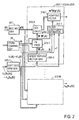
- Fig. 1 shows an exemplary arrangement of an MIMO system to which the present invention is applied.
- each of N transmitters S1 ⁇ SN information series c 1 (i) to c N (i) are encoded in encoders 11-1, ⁇ , 11-N, and the encoded outputs are fed through interleavers 12-1, ⁇ , 12-N to modulators 13-1, ⁇ , 13-N as modulation signals, thus modulating a carrier signal in accordance with these modulation signals to transmit signals b 1 (k) to b N (k).
- transmitted signals b 1 (k) ⁇ b N (k) from the transmitters S1, ⁇ ,SN form N series transmitted signals.
- a received signal r (k) which is received by a multiple output receiver through transmission paths (channels) is input to a multiple output equalizer 31.
- a signal received by the receiver is converted into a baseband signal, which is then sampled at one-half the symbol period ,for example, to be converted into a digital signal, which is then input to the equalizer 31. It is assumed that there are one or more digital signals, the number of which is represented by an integer M. For example, received signals from M antennas are formed into received signals in the form of M digital signals.
- the equalizer 31 delivers N log-likelihood ratios ⁇ 1 [b 1 (k)], ⁇ ⁇ 1 [b N (k)].
- subtractors 22-1, ⁇ , 22-N a priori information ⁇ 1 [b 1 (k)], ⁇ ⁇ 1 [b N (k)] are subtracted from ⁇ 1 [b 1 (k)], ⁇ ⁇ 1 [b N (k)], and results are fed through deinterleavers 23-1, ⁇ , 23-N to be input to soft input soft output (SISO) decoders (channel decoders) 24-1, ⁇ , 24-N to be decoded, whereby the decoders 24-1, ⁇ , 24-N deliver decoded information series c' 1 (i) ⁇ c' N (i) together with ⁇ 2 [b 1 (i)], ⁇ , ⁇ 2 [b N (i)].
- SISO soft input soft output
- subtractors 25-1 ⁇ , 25-N ⁇ 1 [b 1 (i)], ⁇ ⁇ 1 [b N (i)] are subtracted from ⁇ 2 [b 1 (i)], ⁇ , ⁇ 2 [b N (i)], respectively, and results are fed through interleavers 26-1 ⁇ , 26-N to be fed as ⁇ 2 [b 1 (k)], ⁇ ⁇ 2 [b N (k)] to the multiple output equalizer 31 and the subtractors 22-1, ⁇ , 22-N, respectively.
- an interference elimination step it is assumed that it is desirable to obtain a signal from an n-th user (transmitter).
- a soft decision symbol estimate for signals from all users (transmitters) and a channel matrix (transmission path impulse response matrix) H are used to produce a synthesis of interferences by user signals other than from n-th user and interferences created by the n-th user signal itself, or an interference replica H ⁇ B '(k) is reproduced. Then, the interference replica is subtracted from y (k) to produce a difference matrix y '(k).
- the matrix B '(k) represents a replica matrix of the interference symbol.
- w n (k) which is obtained in this manner is used to calculate w n H (k) ⁇ y '(k), and a result of calculation is fed through deinterleaver 23-n to be input as ⁇ 1 [b n (i)] to the decoder 24-n where a decoding calculation is made.
- M received signals r m (k) are supplied to a received matrix generator 311 where a received matrix y (k) is generated and is fed to equalizers 312-1 to 312-N for each user.
- the channel matrix H which is calculated by a channel estimator 28 is also supplied to the equalizers 312-1 to 312-N.
- All of equalizers 312-1 to 312-N have identical functional arrangements and process in an identical manner, and accordingly, a typical one of them (312-1) will be described.
- soft decision transmitted symbol estimates b' 1 (k) to b' N (k) are supplied to an interference replica matrix generator 314-1 where an interference replica matrix B ' 1 (k) is generated according to the equations (29) to (31), then the matrix B ' 1 (k) is subject to a filter processing according to the channel matrix H in a filter processor 315-1, and a resulting interference replica component H ⁇ B ' 1 (k) is subtracted from the received matrix y 1 (k) in a difference calculator 316-1 to produce a difference matrix y ' 1 (k).
- the channel matrix H or a reference signal which will be described later is input to a filter coefficient estimator 317-1 to determine the filter coefficient w 1 (k) which is used to eliminate the residue of the interference component.
- the channel matrix H and a covariance ⁇ 2 of a noise component and soft decision transmitted symbols b' 1 (k) to b' N (k) from the soft decision symbol generator 313-1 are input to the filter coefficient estimator 317-1 to determine the filter coefficient w 1 (k) which minimizes the equation (32) according to the minimum mean square error criteria.
- a specific example of determining the filter coefficient w 1 (k) will be described later.
- the difference matrix y ' 1 (k) is processed with the filter coefficient w 1 (k) in an adaptive filter processor 318-1, and ⁇ 1 [b 1 (k)] is delivered as an equalized output for the received signal which corresponds to the transmitted signal from user 1.
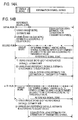
- FIG. 3 A processing procedure for the multiple input multiple output turbo-reception method according to the described embodiment of the present invention is shown in Fig. 3.
- a channel value h mn (q) and a covariance ⁇ 2 of a noise component are calculated from a received signal r(k) and each training signal b n (k).
- the channel matrix H is calculated from the channel value h mn (q).
- the received signal y (k) is generated from the received signal r(k).
- the interference replica matrix B ' n (k) is generated according to the equations (29) to (31) using the respective soft decision transmitted symbol estimates b' n (k) .
- the interference component replica H ⁇ B' n (k) for the received signal from the n-th transmitter is calculated.
- the interference component replica H ⁇ B ' n (k) is subtracted from the received matrix y (k) to provide the difference matrix y ' n (k).
- the filter coefficient w n (k) which is used to eliminate the residue of interference remaining in the received signal from the n-th transmitter is determined according to the minimum mean square error criteria so as to minimize the equation (32).
- a filter processing according to the filter coefficient w n (k) is applied to the difference matrix y ' n (k) to obtain the log-likelihood ratio ⁇ 1 [b n (k)].
- the a priori information ⁇ 2 [b n (k)] is subtracted from ⁇ 1 [b n (k)] and the result is deinterleaved and decoded to deliver the log-likelihood ratio ⁇ 2 [b n (k)].
- step S11 an examination is made to see whether or not the number of decoding operations, namely, the number of turbo-reception processings has reached a given number. If the given number is not reached, the operation goes to step S12 where the extrinsic information ⁇ 1 [b n (k)] is subtracted from the log-likelihood ratio ⁇ 2 [b n (k)], and its result is interleaved to determine the a priori information ⁇ 2 [b n (k)], thus returning to step S3. If it is found at step S11 that the number of decoding operations has reached the given number, a resulting decoding output is delivered at step S13.
- the channel estimator 28 determines the channel value (transmission path impulse response) h mn (q) appearing in the equation (33) and the mean power ( ⁇ 2 ) of the noise v m (k). Normally, a unique word (training signal) which is known to the receiver is inserted at the beginning of each frame to be transmitted on the transmitting side, as shown in Fig. 4A, and the receiver utilizes the unique word (known signal) as a training series to estimate the channel value h mn (q) using RLS (recursive least square) technique.
- Each of the channel decoder 24-1, ⁇ , 24-N delivers +1 if a log-likelihood ratio ⁇ 2 [b 1 (i)], ⁇ ⁇ 2 [b N (i)] is positive, and -1 if the latter is negative as a decoded code signal (or transmitted encoded symbol hard decision value) b and 1 (i), ⁇ , b and N (i), which are fed iteratively through interleavers 27-1, ⁇ , 27-N to the channel estimator 28.
- the received signal r (k) is input to the channel estimator 28 together with a unique word which is fed from a unique word memory 29 to serve as a reference signal.
- the channel estimator 28 estimate each h mn (q) according to the equation (33) and ⁇ 2 value according to the least square technique. This estimation can be made in a similar manner as the estimation of an impulse response when adaptively equalizing the received signal with an adaptive filter by estimating an impulse response of a transmission path.
- the concept according to the present invention is illustrated in Fig. 4B.
- the purpose of the concept is to estimate the channel value iteratively in each stage of the iterated equalization processing of the same received signal or during the each iteration of the turbo-reception processing.
- the channel value is estimated using only the unique word as a reference signal, and the estimated channel value is used to equalize the received signal and to estimate the transmitted symbol.
- the channel estimation is made using the unique word as the reference signal, and the symbol estimate (hard decision value) which is obtained during the previous decoding processing is also used as the reference signal to perform a channel estimation of the entire frame.
- the hard decision is rendered by delivering +1 when the logic-likelihood ratio ⁇ 2 [b n (i)] from the decoder 24-n is positive, and delivering -1 if the later is negative.
- the certainty that is rendered when the log-likelihood 5 is determined to be +1 is greater than the certainty when the logic-likelihood 0.3 is determined to be +1. Accordingly, an interative channel estimation method which uses a threshold value to designate hard decision value b n (i) which is likely to be certain will be described below.
- a threshold between 0 and 1 is provided, and when the absolute magnitude of a soft decision value b' n (i) is greater than the threshold value, a corresponding hard decision value b and n (i) is preserved to be used in the iterative channel estimation.
- the threshold value is chosen to be 0.9
- those of hard decision values b and n (i) which correspond to soft decision values b' n (i) having absolute magnitudes equal to or greater than 0.9 are selected. It is believed that the certainty of the selected hard decision value b and n (i) is high in view of the fact that the threshold value is as high as 0.9, and accordingly, it is believed that the accuracy of the iterative channel estimation which is made using such hard decision values can be improved. However, it is also considered that because the number of selected symbols is reduced, the accuracy of the iterative channel estimation may be influenced and becomes degraded. Accordingly, it is necessary that an optimum threshold value be choosed between 0 and 1.
- threshold value is to be 1, if follows that there is no hard decision value b and n (i) which is selected, stating to the effect that no iterative channel estimation takes place. Accordingly, a threshold value on the order of 0.2 to 0.8 is chosen, as will be further described later.
- those of transmitted symbol estimates (hard decision values) b and 1 (i), ⁇ ,b and N (i) for the information symbol series during the first transmission which are determined to be likely to be certain according to the threshold value are fed from the outputs of the interleavers 27-1, ⁇ , 27-N to a previous symbol memory 32 to be stored therein as a previous transmitted symbol estimate.
- the unique word is initially used to make a channel estimation, and those of estimated transmitted symbol hard decision estimates b and 1 (i), ⁇ , b and N (i) which have been determined to be likely to be certain are read from the previous symbol memory 32 to be fed to the channel estimator 28 to make a channel estimation, namely, a channel estimation for the entire frame.
- a resulting estimate h mn (q) and ⁇ 2 are used to perform an equalization and decoding (the estimation of transmitted symbol) with respect to the received signal r (k).
- those symbol values among the estimated transmitted symbols which had been determined to be likely to certain according to the threshold are iused to update the content of the previous symbol memory 32.
- an estimation using the unique word and an estimation using those of the previously estimated transmitted signals which are determined to be likely to be certain are used to make a channel estimation of the entire frame during a subsequent iteration of the equalization and decoding.
- the estimated channel is used to perform the equalization and decoding (the estimation of transmitted symbol) and to update the previous symbol memory 32.
- those of the transmitted symbol hard decision values b and 1 (i), ⁇ , b and N (i) from the decoders which are determined to be likely to be certain according to the threshold value may be directly stored in the previous symbol memory 32 to update it, and when the symbol values stored in the previous symbol memory 32 are to be utilized, they will be fed through the interleavers 27-1, ⁇ , 27-8 to be input to the channel estimator 28.
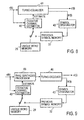
- a function as indicated in Fig. 5 is added to each decoder 24-n.
- the value b' n (i) is compared against a threshold value Th from a threshold presetter 243, thus delivering 1 when b' n (i) is equal to or greater than Th and delivering 0 when it is less than Th.
- the log-likelihood ratio ⁇ 2 [b n (i)] is input to a hard decision unit 244, which delivers +1 if ⁇ 2 [b n (i)] is positive and delivers -1 if the latter is negative as a symbol hard decision value b and n (i).
- the symbol hard decision value b and 1 (i) is fed through a gate 245 which is opened when a corresponding symbol soft decision value is equal to or greater than the threshold value, and is passed through the interleaver 27-n shown in Fig. 1 to be fed to the previous symbol memory 32, thus updating the stored symbols.
- a procedure of the channel estimation which also utilizes a symbol hard decision value or values which are likely to be certain is shown in Fig. 6.
- a channel estimation is made with a received signal r(k) and a unique word.
- an examination is made to see if the decoding processing is for the first time, and if it is, at step S3, the estimated channel value h mn (q) is used to perform the equalization and decoding processing or the operations shown at steps S3 to S10 in Fig. 3.
- a transmitted symbol hard decision is rendered with respect to the log-likelihood ratio ⁇ 2 [b n (i)] to determine a hard decision value b and n (i).
- step S6 by examining whether the symbol soft decision value b' n (i) is equal to or greater than the threshold value Th or not, those of the symbol hard decision values b and n (i) which are likely to be certain are determined.
- step S7 the symbol hard decision value or values which are likely to be certain are used to update the content of the previous symbol memory 32.
- step S8 an examination is made to see whether or not the number of decoding operations has reached a given value, and if not, the operation returns to step S1, or more exactly, going through the step S12 shown in Fig. 3 and returning to the step S1 shown in Fig. 3.
- step S9 a previous stored symbol, namely, a hard decision symbol which is likely to be certain is read from the previous symbol memory 32, and it is used together with information symbol series of the received signal r(k) to make a channel estimation, thus transferring to step S3.
- the channel estimation is made from the beginning using the unique word as a reference signal, but it is also possible that only the hard decision symbol which is likely to be certain may be used as the reference signal during a second and a subsequent iteration.
- an examination is made to see if this processing is for the first time at step S1', and if it is, the unique word is used as a reference signal together with the received signal to estimate the channel value.
- the operation transfers to the equalization and the decoding processing which take place at step S3.
- step S1' If it is found at step S1' that the processing is not for the first time, before the channel estimation is made, a previously stored channel estimate and various processing parameters are set up at S4', whereupon the operation transfers to step S9.
- w n (k) (HG(k)H H + ⁇ 2 I) -1 ⁇ h
- I represents a unit matrix
- ⁇ 2 an internal noise power of a receiver (covariance of noise component)
- ⁇ 2 I a covariance matrix of noise component
- G (k) corresponds a squared error of the channel estimation.
- E [ ] represents a mean, diag a diagonal matrix (having elements which are not along the diagonal being zero's).
- h comprises all the elements in the (Q-1) ⁇ N+n-th column of H appearing in the equation (23).
- Input to the filter coefficient estimator 317-1 of the multiple output equalizer 31 as shown in Fig. 2 are the channel matrix H and the noise power ⁇ 2 which are estimated in the channel estimator 28 and the soft decision transmitted symbols b' 1 (k) to b' N (k) from the soft decision symbol generator 313-1 to calculate the residual interference elimination filter coefficient w n (k) according to the equations (34) to (38).
- D (k) have elements having a value of 1 for those elements which are located at n-row and n-column while all other elements are equal to 0.
- w n (k) does not depend on k, and accordingly, an inverse matrix calculation at every discrete time k can be dispensed with, thus reducing the quantity of calculation.
- the matrix inversion lemma for the inverse matrix is applied to the equation (41).
- a -1 B-BC(D+C H BBC) -1 C H
- a -1 B-BC(D+C H BBC) -1 C H
- w n (k) h , indicating that w (k) can be determined by only h .
- only h which is represented by the equation (38) in the channel matrix H from the channel estimator 28 may be input to the filter coefficient estimator 317-1.
- the approximation also allows the quantity of calculation for the equation (34) to be reduced.
- the quantity of the calculation can be further reduced.
- ⁇ is greater than 0.6, BER (error rate) will be degraded, preventing a correct decoding result from being obtained. It is also contemplated to make ⁇ to be variable in accordance with the reliability of a decoding result. For example, ⁇ may be chosen for each iteration of the decoding processing. In this instance, the reliability of the decoding result will be normally improved with the number of iterations of the decoding processings and accordingly, an increased value may be chosen for ⁇ depending on the number of iterations of the decoding processing. Alternatively, the reliability of an entire decoded frame may be determined upon each iteration of the decoding processing, and the value of ⁇ may be chosen in accordance with the reliability thus determined.
- a decoding result may be compared against a decoding result which is obtained during an immediately preceding iteration, and a number of hard decision symbols which changed from the previous decoding operation may be counted, for example. Thus, where there is an increased number of changed decision symbols, the reliability may be determined to low while when the number of changed hard decision symbols is small, the reliability may be determined to be high.
- Equation (35) which is used when determining the filter coefficient w n (k) for MMSE (minimum mean square error) filter is desirably changed as follows:
- D (k) has elements located at n-row and n-column, which are represented as follows: E[(b n (k)+f(b' n (k))) ⁇ (b n (k)+f(b' n (k)))*] where ( ) represents a complex conjugate.
- FIG. 7A An exemplary functional arrangement which estimates an adaptive filter coefficient w n (k) when reflecting an error correction decoding result into a signal being detected is shown in Fig. 7A where a signal being detected is chosen as a transmitted signal b 1 (k) from a first transmitter.
- a soft decision transmitted symbol b' 1 (k) is input to a function calculator 331-1 to calculate a function f(b' 1 (k)).
- Soft decision transmitted signal b' 1 (k) to b' n (k) from N decoders and f(b' 1 (k)) are input to an error matrix generator 332-1 to calculate and generate an error matrix G (k) according to the equations (35), (36) and (48).
- the error matrix G (k), an estimated channel matrix H and noise power ⁇ 2 are input to a filter coefficient generator 333-1 where a calculation of the equation (34) is made to estimate an adaptive filter coefficient w n (k).
- f(b' n (k)) is also input to an interference replica matrix generator 314-1, thus generating an interference replica matrix B '(k) represented by the equation (29) according to the equations (30) and (43).
- the filter coefficient w n (k) is used in filtering a difference matrix y '(k) in an adaptive filter 318-1, thus yielding a log-likelihood ratio ⁇ 1 [b 1 (k)].
- the function calculator 331-1 shown in Fig. 7A is omitted, and only the soft decision transmitted symbols b' 1 (k) to b' N (k) are input to the error matrix generator 332-1 in order to calculate the equation (34).
- the interference replica matrix B '(k) is generated at step S4, and after processings at steps S5 to S7, the filter coefficient w n (k) is determined at step S8. If a calculation of the equation (34) is made during the processing at step S8, the soft decision transmitted symbols b' 1 (k) to b' N (k) are used to calculate the equations (35) to (37) to generate an error matrix G (k) at step S8-2, and the error matrix G (k), the estimation channel matrix H and the noise power ⁇ 2 are used to calculate the equation (34) to determine an adaptive filter coefficient w n (k) at step S8-3, as shown in Fig. 7B.
- a soft decision transmitted symbol b' n (k)of a signal which is to be detected may be calculated at step S8-1 before entering the step S4, and this may be used at step S4 where the equation (31) is replaced by the equation (43), or in other words, the equations (29), (30) and (43) may be used to generate an interference replica matrix B' (k), and at step S8-2, the equation (37) may be replaced by the equation (48).
- f(b' n (k)) is chosen to be equal to ⁇ b' n (k) or ⁇ b' n (k) 2 and when ⁇ is chosen to be variable, ⁇ may be determined in accordance with the number of processing operations or the reliability of the entire decoded frame at step S8-1-1, and 1+(2 ⁇ + ⁇ 2 )b' n (k) 2 may be calculated and used as f(b' n (k)) at step S8-1-2.
- the technique of reflecting an error correcting result into a signal being detected is also applicable to a single user turbo-receiver which has been described initially in connection with the prior art.
- the approximation represented by the equations (39) and (40) can be applied, and in this instance, only a matrix h shown by the equation (38) which is supplied from the channel estimator 28 may be input to the filter coefficient generator 333-1, as indicated in broken lines in Fig. 7A.
- the adaptive filter coefficient w n (k) is determined according to the equation (34) or by using the channel matrix H , but the use for the channel matrix H can be dispensed with.
- the error matrix G appearing in the equation (34) becomes a unit matrix.
- the difference matrix y '(k) and the training signal either alone or in combination with a hard decision transmitted symbol b and n (k), preferably b and n (k) having a high reliability in the sense mentioned above are input to the filter coefficient generator 333-1 to calculate the adaptive filter coefficient w n (k) in a sequential manner by application of RLS (recursive least square) technique.
- the error matrix G depends on a discrete time k, during a second and a subsequent iteration of the decoding operation, it becomes necessary to update the adaptive filter coefficient w n (k) from symbol to symbol, and as mentioned previously, it is preferred to determine the adaptive filter coefficient w n (k) by using the channel matrix H .
- Using not only known information such as a unique word in the iterative channel estimation, but also using a hard decision value of information symbol, in particular one which is likely to be certain as a reference signal is applicable not only in the described multiple input multiple output turbo-reception method, but also generally to a turbo-reception method in which a channel (transmission path) of a received signal is estimated from the received signal and the known signal, the estimated channel value is used to process the received signal and to decode it, and the decoded signal is used in iterating the processing according to the estimated channel value and the decoding processing upon the same received signal.
- Fig. 8 shows an example in which a hard decision value of information symbol is used in a channel estimation turbo-equalizer 41.
- the turbo-equalizer 41 determines a linear equalization filter coefficient in accordance with an estimated channel value.
- the received signal is processed by such a linear equalization filter, the processed signal is decoded, and the decoded signal is utilized in the iterative processing of the same received signal.
- a received signal r(k) is input to the turbo-equalizer 41 and is also fed to a channel estimator 42 where a channel value (transmission path characteristic) is estimated on the basis of the received signal r(k) and a unique word from a memory 29.
- the received signal r(k) is subject to an equalization processing in the turbo-equalizer 41 in accordance with the estimated channel value, and is then subject to a decoding processing, whereby decoded data c'(i) and a soft decision value b'(i) are delivered.
- the soft decision value b'(i) is input to a symbol designator 43. If its soft decision value b'(i) has an absolute magnitude which is equal to or greater than a threshold, the corresponding hard decision value b and(i) is stored in a previous symbol memory 32 as one which is likely to be certain (as having a high reliability) to update it.
- the channel estimation which takes place in the channel estimator 42 takes place by using not only the unique word but also the hard decision value b and(i) of information symbol which is stored in the previous symbol memory 32.
- the turbo-equalizer 41 may comprise the receiver shown in Fig. 1, for example, from which the iterative channel estimator 28, the unique word memory 29 and the previous symbol memory 32 are removed. It may comprise a receiver shown in Fig. 31.
- H is as defined by the equation (8), and h ⁇ [H(Q-1),...,H(0)] T
- H ( ) is as defined by the equation (5)
- ⁇ 2 E[ v 2 ] (variance of noises)
- ⁇ (k) diag[1-b' 2 (k+Q-1),...,1,...,1-b' 2 (k-Q+1)]
- the channel matrix H ( ) is estimated, and the channel matrix H ( ) is used to determine the equalization filter coefficient w (k), the received signal is filtered according to the filter coefficient w (k), and the processed output is subject a decoding processing. Accordingly, by using a hard decision information symbol of a high reliability in the channel estimation during the iterative recessive processing, there can be obtained a more correct channel estimation.
- Fig. 9 shows an example of a turbo-receiver in which the iterative channel estimation method is applied in the iterative reception in which RAKE synthesis takes place.
- a received signal r(k) is fed to a RAKE synthesis processor 45 and a channel estimator 42.
- a channel value is estimated on the basis of the received signal r(k) and a unique word in the channel estimator 42, and a compensation for a phase rotation which each symbols has experienced on a transmission path as well as RAKE synthesis take place in accordance with the estimated channel value in the RAKE synthesis processor 45, or a time diversity processing takes place to be delivered to a turbo-decoder 46.
- the turbo-decoder 46 delivers decoded data c'(i) and a soft decision value b'(i).
- the soft decision value b'(i) is input to a symbol designator 43, and as in described examples, a hard decision value b and(i) of an information symbol which is likely to be certain is stored in a previous symbol memory 32 by updating it.
- a hard decision value b and(i) of an information symbol which is likely to be certain is stored in a previous symbol memory 32 by updating it.
- Fig. 10 shows an example of a turbo-receiver in which the described iterative channel estimation method is applied in the iterative reception using an adaptive array antenna.
- a received signal r (k) is received by an adaptive array antenna receiver 47, and is then branched into a channel estimator 42 where a channel estimation takes place in accordance with the received signal in combination with a unique word.
- the estimated channel value is used to determine the weights to be applied to each antenna element or corresponding reception paths in an array weight determining unit so that the principal beam of the antenna directivity response of the adaptive array antenna receiver 47 is directed toward the oncoming direction of an intended wave while null is directed toward the oncoming direction of an interfering wave, and such weights are applied to applicable locations.
- a received output from the adaptive array antenna receiver 47 is fed to a turbo-decoder 46 to be decoded, whereby decoded data c'(i) and a soft decision value b'(i) are delivered.
- the soft decision value b'(i) is input to a symbol designator 43, and a hard decision value which is likely to be certain is stored in a previous symbol memory 32 by updating it.
- the hard decision value of information symbol which is obtained during the previous iteration is used in the channel estimation in the channel estimator 42 together with the unique word. In this manner, the channel estimation takes place more correctly, resulting in a more accurate control of the antenna directivity response and improving the quality.
- the turbo-equalizer 41 shown in Fig. 8 is schematically shown in Fig. 11A, and as shown, it comprises a series connection of a soft input soft output (SISO) equalizer 41a and an SISO decoder 41b, and the operation iterates between the equalizer 41a and the decoder 41b.
- the turbo-decoder 46 shown in Figs. 9 and 10 is schematically shown in Fig. 11B, and as shown, it comprises a series connection of a SISO decoder 46a and an SISO decoder 46b, and an iterative decoding operation takes place between the decoders 46a and 46b.
- the turbo-decoder 46 shown in Figs. 9 and 10 may comprise a single SISO decoder.
- a received signal is initially processed in an iterative receiver (turbo-receiver) 49 in accordance with a channel value which is estimated by a channel estimator 42, the processed signal is decoded, and a result of the decoding operation is provided in the form of decoded data (symbol) c'(i) and its soft decision value b'(i).
- the soft decision value b'(i) is compared against a threshold value in a symbol designator 43 to determine whether or not a corresponding decoded data c'(i) (symbol hard decision value) is likely to be certain.
- the hard decision value is stored in a previous symbol memory 32 by updating it, and during a second and a subsequent iteration of the processing using the estimated channel value and the decoding processing, the symbol hard decision value obtained during the previous iteration is used in addition to known information such as unique word in the channel estimation which takes place in the channel estimator 42 to provide a more correct channel estimation.
- Fig. 13 shows an exemplary processing procedure of an iterative turbo-reception method which also uses a symbol hard decision value.
- a channel value is estimated on the basis of a received signal and a known signal.
- an examination is made to see if this is the first one of the iterative processing, and if it is, the channel value which is estimated at step S1 is used to process the received signal at step S3, and then the decoding processing takes place to determine a symbol hard decision value and a soft decision value.
- a symbol hard decision value which corresponds to the symbol soft decision value and which is likely to be certain is extracted, and at step S5, the extracted symbol hard decision value is used to update a previous symbol hard decision value which is stored in the memory 32.
- step S6 an examination is made to see if the number of decoding processings has reached a given number, and if not, the operation returns to step S1.
- a previous symbol hard decision value is read out from the memory 32 at step S7, and it is used together with an information symbol of a received signal in performing a channel estimation, whereupon the operation transfers to step S3.
- the known signal may not be used during a second and a subsequent iteration.
- RAKE synthesis processor 45 may be inserted between the adaptive array antenna receiver 47 and the turbo-decoder 46, as indicated by broken lines.
- a channel estimation which is necessary for the compensation of a phase rotation of each symbol and the RAKE synthesis in the RAKE synthesis processor 45 may be served by the channel estimator 42, or may take place separately.
- the processing took place on an assumption that the noise is white Gaussian noise.
- v m (k) appearing on the right side of the equation (29) indicating a received signal r m (k) from each antenna is assumed to be white Gaussian noise.
- white Gaussian noise is a signal which follows the Gaussian distribution and have statistical features expressed as follows: where E[ ] represents an expected value and ⁇ 2 a variance.
- White Gaussian noise may be exemplified by thermal noise which is generated in an antenna element. What is influenced by the assumption of white Gaussian noise is ⁇ 2 I portion appearing in the equation (34) which determines the filter coefficient w n (k) or the equation (50) which determines the filter coefficient w n (k). For example, w n (k) appearing in the equation (34) is calculated through the process indicated below.
- the channel matrix H which is estimated by the iterative channel estimator 28 (Fig. 1) or 42 (Fig. 12), ⁇ 2 and the error matrix G (k) which is calculated on the basis of the a priori log-likelihood value are substituted into the equation (34) to calculate the filter coefficient w n (k).
- Fig. 14A shows a unique word and information symbol series which occurs in one frame of a received signal
- Fig. 14B shows the initial processing as well as a subsequent processing.
- the initial processing only the unique word is used as a reference signal, initially estimating the channel matrix H .
- U is estimated using the unique word and the channel matrix estimate H and according to the equation (51).
- the unique word as well as one of information signals (*) estimated during the initial equalization which is determined to be likely to be certain according to the threshold value are both used as reference signals to estimate H again with the same procedure as used during the initial processing, thus estimating U again.
- FIG. 15 A functional arrangement in which a linear equalization is performed by estimating a covariance matrix U of a noise contained in a received signal is shown in Fig. 15 as an example in which a log-likelihood ratio ⁇ 1 [b 1 (k)] is obtained as an equalization output from a multiple output equalizer 31 shown in Fig. 2 for a received signal corresponding to a transmitted signal from a first transmitter.
- a log-likelihood ratio ⁇ 1 [b 1 (k)] is obtained as an equalization output from a multiple output equalizer 31 shown in Fig. 2 for a received signal corresponding to a transmitted signal from a first transmitter.
- Parts corresponding to those shown in Fig. 2 are designated by like reference numerals in Fig. 15 as used in Fig. 2.
- a unique word from a unique word memory 29 or a previous symbol hard decision from a previous symbol memory 32 which is likely to be certain is input to a reference matrix generator 319, which then generates a reference matrix B (k) according to the equations (25) and (26).
- the reference matrix B (k), an estimation channel matrix H and from a channel estimator 28, and a received matrix y (k) from a received matrix generator 311 are supplied to a covariance matrix estimator 321, which then calculates the equation (51) to obtain an estimated matrix ⁇ for a covariance matrix U.
- Soft decision transmitted symbols b 1 '(k) , ⁇ ,b n '(k) from a soft decision symbol generator 313-1 are input to an error matrix generator 322-1, where an error matrix G 1 (k) corresponding to the square error of the channel estimation is generated according to the equations (35), (36) and (37).
- the error matrix G 1 (k), the estimated covariance matrix ⁇ and the estimatied channel matrix H and are supplied to a filter estimator 323-1, where the equation (52) is calculated to estimate a filter coefficient w 1 (k).
- the filter coefficient w 1 (k) and the difference matrix y '(k) from a difference calculator 316-1 are fed to an adaptive filter 318-1 where a filter processing w 1 (k) H y '(k) is applied to y '(k), and its result is delivered as a log-likelihood ratio ⁇ 1 [b 1 (k)].
- a function calculator 331-1 as shown in Fig. 7A is provided, as indicated by broken lines in Fig. 15, to calculate f(b' n (k)), and an interference replica matrix generator 314-1 uses the equation (43) rather than the equation (31), and a error matrix generator 322-1 uses the equation (48) rather than the equation (37).
- a received signal r(k) and a known signal are used to estimate a channel matrix H
- a known signal for example, a unique word
- an examination is made to see if this processing is for the first time, and if it is, the known signal, the estimated channel matrix H and and the received signal r(k) are used to calculate the equation (51) to determine an estimated covariance matrix ⁇ at step S3.
- step S4 the estimated channel matrix H and , the estimated covariance matrix ⁇ and an error matrix G (k) which comprises symbol soft decision values are used to calculate the equation (52) to estimate a filter coefficient w n (k).
- the estimated channel matrix H and and the filter coefficient w n (k) are used to equalize the received signal or to calculate the equation (27) to determine w n H (k) ⁇ y '(k) to obtain a log-likelihood ratio ⁇ 1 [b n (k)], subsequently performing a decoding process to estimate a hard decision value and a soft decision value of a transmitted symbol.
- Step S6 Purpose of step S6 is to determine a symbol hard decision value which corresponds to a symbol soft decision value which exceeds a threshold value and which is likely to be certain (or having a high reliability). This symbol hard decision value is used to update a symbol hard decision value which is stored in a previous symbol memory 32. Subsequently, an examination is made at step S8 to see if the number of the decoding processings has reached a given value, and if not, the operation returns to step S1. However, if a given number is reached, the processing upon this received frame is completed.
- step S2 If it is found at step S2 that the iterative processing is not for the first time, namely, for a second or a subsequent iteration, a symbol hard decision value is read from the previous symbol memory 32 at step S9, and is used together with information symbol in the received signal to estimate the channel matrix H , subsequently transferring to step S3.
- a function f(b' n (k)) may be calculated at step S10, as shown in broken lines in Fig. 16, and it may be used to obtain the error matrix G (k).
- the hard decision transmit symbol may not be used in the estimation of the covariance matrix ⁇ .
- the estimation of the covariance matrix U is applicable to a single user turbo-reception method by allowing it to serve in place of ⁇ 2 I in the equation (50).
- it may be used in a RAKE synthesis processing reception illustrated in Fig. 9 or a turbo-reception using an adaptive array antenna reception shown in Fig. 10, irrespective of a single user or multi-user application, or more generally, in a channel estimation in a channel estimator 42 and an estimation of the covariance matrix U during the iterative decoding operation shown in Fig. 12.
- RAKE reception only the channel estimation may be used.
- received signals r 1 , ⁇ ,r M are equalized in a multiple output equalizer 31 to determine log-likelihood ratios ⁇ 1 [b(k)], ⁇ , ⁇ N [b(k)], but in a modification (2) of the first aspect of the present invention, there are provided a plurality of equalizer stages in cascade connection in a manner such that the number of outputs is reduced toward a later stage equalizer.
- Fig. 17 shows that the equalizer is divided in two parts where a prestage equalizer (multi-user equalizer) 71 cancels an interfering component which is located outside an equalization range of a poststage, single user equalizer 21'.
- a preprocessing including a soft interference cancel and a linear filtering according to MMSE(minimum mean square error) criteria, for example, is made, and subsequently, the poststage equalizer 21' performs an equalization of a single user having a number of paths equal to Q.
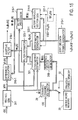
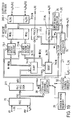
- FIG. 18 An arrangement of a multiple output turbo-receiver according to an embodiment which is based on this fundamental concept of the first aspect of the invention (2) of the turbo-reception method and an exemplary arrangement of MIMO system which incorporates the present invention is shown in Fig. 18. It is to be understood that parts corresponding to those shown in Fig. 1 are designated by like reference characters as used before, without repeating their description. (The same holds true in subsequent description.)
- Transmitted signals from each transmitter is received through transmission paths (channels) by a turbo-receiver 30.
- the received signal r (k) is input to a multi-user equalizer 71, from which signals from N transmitters are delivered in the form of signals u 1 (k), ⁇ , u N (k), each of which is provided in the form it is free from interferences by signals from other transmitters, and channel values ⁇ 1 (k), ⁇ , ⁇ N (k) to be input to single user equalizers 21-1, ⁇ ,21-N.
- These SISO equalizers 21-1, ⁇ ,21-N deliver log-likelihood ratios ⁇ 1 [b 1 (k)], ⁇ , ⁇ 1 [b N (k)]. Subsequent processing remains similar to Fig.
- the channel values ⁇ 1 (k), ⁇ , ⁇ N (k) which are used in the single user equalizers 21-1, ⁇ , 21-N are channel values which are obtained subsequent to the multi-user equalization, and are distinct from the channel matrix H . Accordingly, ⁇ 1 (k), ⁇ , ⁇ N (k) are referred to as post-equalization channel information.
- Equations (23) to (26) are defined in a similar manner as described above in connection with Fig. 1 in consideration of the number of multipaths (channels) Q.
- This soft decision transmitted symbol b' n (k) and a channel matrix H are used to generate a replica H ⁇ B '(k) of an interfering signal, which is then subtracted from the received matrix y (k).
- y' n (k) ⁇ y(k)-H ⁇ B'(k) H ⁇ (B(k)-B'(k))+n(k)
- B'(k) [b' T (k+Q-1)....b' T (k)...b' T (k-Q+1)] T
- a contribution from the signal of the n-th user (transmitter) to the received matrix r (k) is only that resulting that from the symbol [b n (k), b n (k-1), ⁇ , b n (k-Q+1)].
- the interference replica includes interference components from the future symbols.
- the difference matrix y '(k) defined by the equation (27)' is distinct from the difference matrix y '(k) defined by the equation (27).
- a next step in the prestage processing in the equalizer 71 is to eliminate the residue interference which remains after the soft interference cancel, namely, a residual interference component which results from an imperfect synthesis of the interference replica H ⁇ B' (k) and interference components between future symbols from y ' n (k) using MMSE (minimum mean square error) criteria linear filter.
- MMSE minimum mean square error
- this elimination takes place by an arrangement such that a filtering of y ' n (k) using the filter characteristic w n (k) as indicated by the equation (55) is equal to a sum of the symbols [b n (k), b n (k-1), ⁇ , b n (K-Q+1)] each multiplied by channel values ⁇ 1n (k), ⁇ 2n (k), ⁇ , ⁇ Qn (k). Accordingly, what is required is to calculate the equation (55) by determining the filter characteristic w n (k) and the post-equalization channel value (channel information) ⁇ n (k). The derivation of w n (k) and ⁇ n (k) will be described. It is to be noted that while the filter characteristic w n (k) is distinct from the filter coefficient w n (k) given by the equations (32) and (34), similar denotations will be used for purpose of convenience.
- w n (k) and ⁇ n (k) which minimizes the right side of the equation (56) are determined.
- the right side of the equation (56) is defined as m n (k) which is minimized in terms of w and ⁇ .
- ⁇ n (k) diag[D n (k+Q-1),...,D n (k),...,D n (k-Q+1)]
- I represents a unit matrix
- ⁇ 2 noise power a covariance of white Gaussian noise
- m n (k) can be determined according to the equation (61). Accordingly, w n (k) and ⁇ n (k) can then be determined according to the equation (58).
- u n (k), k 0, ⁇ ,B] ⁇ 1 [b n (k)]+ ⁇ p 2 [b n (k)] where ⁇ 1 [b n (k)] represents an extrinsic information fed to a succeeding decoder 24-n, and ⁇ 2 P [b n (k)] a priori information applied to the equalizer 31.
- ⁇ 1 [b n (i)], i 0, ⁇ ,B] ⁇ 2 [b n (i)]+ ⁇ p 1 [b n (i)] where ⁇ 2 [b n (i)] represents an extrinsic information applied to the equalizer 71 and the equalizer 21 during the iteration and the ⁇ 1 P [b n (k)] a priori information applied to the decoder 24-n.
- the arrangement shown in Fig. 18 performs an iterated equalization and decoding to improve an error rate.
- a functional arrangement of the multi-user equalizer 71 will be briefly described with reference to Fig. 19.
- the received signal r (k) from the receiver 70, and a known series signal such as a unique word series used for channel estimation which corresponds to each transmitter and which is fed from a unique word memory 29 are input to a channel estimator 28 in order to estimate a channel matrix H .
- a priori information ⁇ 1 P [b n (i)], ⁇ , ⁇ 1 P [b N (i)] are subtracted from the log-likelihood ratios ⁇ 2 [b 1 (i)], ⁇ , ⁇ 2 [b N (i)] delivered from the respective decoders 24-1, ⁇ , 24-N to derive extrinsic information ⁇ 2 [b 1 (k)], ⁇ , ⁇ 2 [b N (k)], which is then input to soft decision symbol estimators 313-1, ⁇ , 313-N where soft decision transmitted symbols b' 1 (k), ⁇ , b' N (k) are calculated according to the equation (15) and are then input to an interference matrix generator 72.
- a matrix B '(k) of symbol estimates which can be interference signals from other transmitters are generated for each n according to the equations (29)', (53) and (54).
- a product of these N matrixes B '(k) and the channel matrix H is generated by other interfering signal estimators 73-1, ⁇ , 73-N, respectively, thus determining the replica of interfering components H ⁇ B (k).
- the soft decision transmitted symbols b' 1 (k), ⁇ ,b' N (k) are input to an error matrix generator 75 where error matrices ⁇ 1 (k), ⁇ , ⁇ N (k) are generated according to the equations (64), (66) and (67).
- error matrices, the channel matrix H and the noise power ⁇ 2 are input to a filter characteristic estimator 76 where the filter characteristic w n (k) and the post-equalization channel information ⁇ n are estimated according to the equations (58), (60), (61), (63) and (65).
- filter characteristics w 1 , ⁇ , w N and difference matrixes y ' 1 (k), ⁇ , y ' N (k) are multiplied together in filter processors 77-1, ⁇ , 77-N, respectively, or the difference matrixes are filtered, thus determining a component u 1 (k), ⁇ , u N (k) of the received signal for the symbol [b n (k), b n (k-1), ⁇ , b n (K-Q+1)] from each user and for each path, from which interferences from other user signals are eliminated.
- FIG. 20 A processing procedure for the turbo-reception method according to the first aspect of the invention (2) is shown in Fig. 20 where steps corresponding to those shown in the procedure of Fig. 3 are designated by like step numbers as used before.
- the calculation of the interference replica matrix B ' n (k) which takes place at step S4 follows the equations (29)', (53) and (54).
- the step S13 uses the soft decision transmitted symbol b' n (k) to generate the error matrix ⁇ n (k) according to the equations (64), (66) and (67).
- Step S14 uses the channel matrix H , the noise power ⁇ 2 and the error matrix ⁇ n (k) to determine the residual interference eliminating filter w n (k) and the channel information ⁇ n according to the equations (58), (60), (61), (63) and (65).
- Step S15 filters the difference matrix y ' n (k) according to the residual interference eliminating filter characteristic w n (k) to determine u n (k).
- a single user equalization is applied to each filtered result u n (k) to determine the log-likelihood ratio ⁇ n [u n (k)], which is then decoded at step S10.
- the procedure is similar to that shown in Fig. 3.
- a previous symbol memory 32 may be provided, as indicated in broken lines in Fig. 19, in association with the channel estimator 28 so that the hard decision transmitted symbol b and n (k) may also be used in the estimation of the channel value, thus permitting the accuracy of estimation to be improved.
- the prestage multiple output equalizer 71 equalizes transmitted signals in N series so that interferences from other series may be separated to provide signals u n of N series and the post-equalization channel information ⁇ n and subsequently, the signal u n of each of N series is processed by the post stage single user equalizer 22-n so as to eliminate intersymbol interference of the same transmitted signal.
- the equalization takes place in two stages which are in cascade connection.
- a cascade connection of three or more stages may also be used.
- Fig. 21 shows that a received signal r m of M series with respect to a transmitted signal of N series is input to a first stage equalizer 81 to provide an equalized signal series er 1 (k) for 1st to U-th transmitted series from which interferencs by (U+1)th to N-th transmitted series is eliminated and its associated post-equalization channel information e ⁇ (k), and an equalized signal series er 2 (k) for (U+1)-th to Nth transmitted series from which interferences by 1st to U-th transmitted series are eliminated and its associated post -equalization channel information e ⁇ 2 (k) while a second stage includes equalizers 82-1 and 82-2.
- er 1 (k) and e ⁇ 1 (k) are input to the equalizer 82-1 where they are equalized to provide an equalized signal series er 3 (k) for 1st -U 1 -th transmitted series among the 1 st to Uth transmitted series from which interferences by (U 1 +1)-th to U-th transmitted signal are eliminated and its associated post-equalization channel information e ⁇ 3 , an equalized signal series er 4 (k) for (U 1 +1)-th to U 2 -th transmitted series among the 1st to U-th transmitted signal from which interferences by the 1-st to U 1 -th transmitted series and U 2 -th to U-th transmitted signal are eliminated and its associated post-equalization channel information e ⁇ 4 (k), and an equalized signal series er 5 (k) for (U 2 +1)-th to U-th transmitted series among 1-st to U-th transmitted series from which interferences by 1-st to U 2 -th transmitted series are eliminated and its associated post-equalization channel information
- equalized signal series er 2 (k) and the channel information e ⁇ 2 (k) are input to the equalizer 82-2 in the second stage to provide an equalized signal series er 6 (k) and an associated post-equalization channel information e ⁇ 6 (k), and an equalized signal series er 7 (k) and its associated post-equalization channel information e ⁇ 7 (k).
- equalizers 83-1 to 83-5 in a third stage represent single user equalizers shown in Fig. 18.
- an input equalized signal to the equalizer 83-3 may comprise two transmitted signals, and the equalizer 83-3 can eliminate mutual interferences between the two transmitted signals to provide a set of two equalized signals and their associated post-equalization channel information, which are in turn supplied to and equalized by next succeeding single user equalizers 84-1 and 84-2.
- the equalizer 83-4 may receive the equalized signal er 6 (k) and the channel information e ⁇ 6 (k) to eliminate mutual interferences for each of the transmitted signals which constituted the equalized signal er 6 (k), such as each of three transmitted signals, each of which may be interfered by two other transmitted signals as well as an intersymbol interference of each transmitted signal due to multipaths.
- one or more of the equalizers 82-1 and 82-2 in the second stage may be arranged so that an equalized signal may be simultaneously obtained for each of a plurality of transmitted signals.
- equalizers in a first stage deliver a plurality of equalized signal series and a set of post-equalization channel information
- one or more equalizers may be provided in each of one or a plurality of stages which are in cascading connection for each equalized signal series and its associated set of post-equalization channel information so that an equalized output or a log-likelihood ratio ⁇ 1 [b n (k)] may be delivered finally for each of the 1st to N-th transmitted series.
- the equalization takes place in multiple stages which are in cascade connection, it is preferred that the number of paths Q for which interferences are to be eliminated be reduced toward a later stage so that the quantity of calculation can be reduced. In this instance, an interferring component from a path which disappears in a later stage be eliminated in an immediately preceding equalizer stage.
- An equalization processing which occurs in the arrangement of Fig. 21 when a first stage equalizer 81 deals with N transmitted signals, each of which has a number of multi-paths equal to Q to provide a group of equalized signal series er 1 (k) comprising U transmitted signals and their associated post-equalization channel information e ⁇ 1 (k) and a later stage equalizer 82-1 performs an equalization for a number of multipaths equal to Q' for each transmitted series will be described.
- the equation (54)' is intended to provide symbols for a first to U-th transmitted series
- a soft interference cancel This operation of subtracting the interference is referred to hereafter as a soft interference cancel.
- Reflecting an error correction decoding result for a signal being detected into a soft decision transmitted symbol in the manner mentioned above is also applicable to a single user turbo-equalizer receiver shown in Fig. 8, RAKE synthesis turbo-receiver shown in Fig. 9, a turbo-receiver including an adaptive array antenna receiver shown in Fig. 10, a generalized turbo-receiver including a channel estimator 42 shown in Fig. 12.
- a symbol hard decision value which has been determined as being as likely to be certain is also used as a reference signal in the estimation of the channel matrix H and the covariance matrix ⁇ during a second and a subsequent iteration.
- the unique word may be used as a reference signal to utilize the equation (51) to estimate the covariance matrix ⁇ while omitting the estimation of the channel estimation and the estimation of the covariance matrix ⁇ which utilize the symbol hard decision value.
- a modulated output signal b(j) from a modulator 13 is input to a series-parallel converter 14 where each symbol b(j) is sequentially distributed into N series. It is assumed that there are series signal b 1 (k), ⁇ , b N (k), the number N of which is equal to or greater than 2. While not shown, these signals are transmitted from N antennas after convertion into radio frequency signals.
- the received signal r m (k) is generated in a manner as shown in Fig. 30B, for example.
- the multiple output equalizer 31 is constructed in the same manner as shown in Fig. 2, and performs according to a processing procedure as shown in Fig. 3. Accordingly, an extrinsic information ⁇ 1 [b(i)] is subtracted from a log-likelihood ratio ⁇ 2 [b(i)] from a decoder 24 shown in Fig. 22 in a subtractor 25, and the subtracted output is interleaved by an interleaver 26 to provide a priori information ⁇ 2 [b(j)], which is then converted in a series-parallel converter 15 into N series of a priori information ⁇ 2 [b 1 (k)], ⁇ , ⁇ 2 [b N (k)] to be input to the multiple output equalizer 31.
- N series of received signals are subject to a linear equalization in the multiple output equalizer 31 in the similar manner as mentioned previously, delivering N log-likelihood ratio series ⁇ 1 [b 1 (k)], ⁇ ⁇ 1 [b N (k)], which are then input to a parallel-series converter 16 to be converted into a single log-likelihood ratio series ⁇ 1 [b(j)] to be supplied to a subtractor 22.
- the input signal format to the multiple output equalizer 31 is similar to that described in connection with Figs.
- N series log-likelihood ratios ⁇ 1 [b 1 (k)], ⁇ , ⁇ 1 [b N (k)] can be obtained by the equalization which has been mentioned above with reference to Figs. 1 to 3, and it will be readily seen that an iterative decoding processing is permitted by the use of the series-parallel converter 15 and the parallel-series converter 16.
- an n-th or (n-th column) transmitted signal among N parallel transmitted signals will be equalized.
- the embodiment described above in connection with Figs. 4 to 7 is applicable to the reception of the parallel transmission of the N series signals.
- turbo-reception method and the turbo-receiver according to the present invention are also applicable to the reception of convoluted code/turbo-code + interleaver + multi-value modulation such as QPSK, 8PSK,16QAM, 64QAM etc.,, TCM (trellis coded modulation) / turbo TCM.
- M received signals r 1 (k), ⁇ , r M (k) are derived from M antennas #1, ⁇ , #M, but may be derived from a single antenna. Alternatively, M (which is greater than L) received signals may be obtained from L (which is an integer equal to or greater than 2) antennas. While not specifically shown in Fig. 1, received signals from antennas #1, ⁇ , #M are converted into baseband received signals r 1 ⁇ , r M in a baseband converter and sampled to provide digital signals r 1 (k), ⁇ , r M (k) at discrete time k.
- the frequency of the sampling signal from the sampling signal generator 62 is chosen so that each sampling period of the received signals r 1 (k), ⁇ , r 4 (k) input to the turbo-receiver 30 coincides with the sampling period which is used when a single received signal r M (k) is received per antenna.
- Fig. 24 illustrates the effect of an iterative channel estimation (according to the fourth aspect of the invention).
- the abscissa indicates a threshold value Th.
- Fig. 25 shows an error rate characteristic of an MIMO reception method in which a transmitted symbol hard decision value which is determined to be likely to be certain according to a threshold value is used in the channel estimation or which employs an iterative channel estimation in a form of a curve 66.
- an error rate characteristic with a perfect channel estimation is shown as a curve 67 while an error rate characteristic in which a hard decision value of information symbol is not used in a channel estimation or only a single channel estimation is made without iteration is shown by a curve 68. It will be seen from this graphic illustration that when the iterative channel estimation is used, the error rate characteristic approaches to that obtained by a perfect channel estimation.
- the channel estimation method mentioned above by determining whether a hard decision value is or is not likely to be certain on the basis of a decoded soft decision value, and by using symbol information having a hard decision value which is likely to be certain in the channel estimation during the next iteration, the channel estimation can be performed more correctly, allowing a decoding quality to be improved.
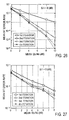
- Three users are chosen to be of an equal power.
- Fig. 26 shows a result of simulation of BER (bit error rate) characteristic of a turbo-receiver which estimates H and ⁇ as shown in Figs. 14, 15 and 16, and Fig. 27 shows BER characteristic which directly uses the turbo-receiver shown in Fig. 1 (which employs the method shown in Fig. 13).
- the noise comprises only white Gaussian noise, and it is seen that two or more iterations of the channel estimation and the decoding processing has little effect.
- Fig. 27 it will be seen from Fig. 27 that as the number of iterations is increased, an improvement in the BER characteristic is achieved, and in addition, BER is considerably less than that shown in Fig. 26 for the same E b /N o .
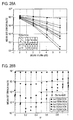
- Fig. 28 shows BER characteristic of a multiple output turbo-receiver shown in Fig. 1 and a multiple input multiple output turbo-receiver in which an error correction decoding result is reflected into b' n (k), with plotted points shown in black for the former and in white for the latter.
- a circle represents an initial run, a down-directed triangle a second iteration, a diamond a third iteration, a left-directed triangle a fourth iteration and a right-directed triangle a fifth iteration.
- Fig. 28A shows a result of a simulation for the BER characteristic plotted against E b /N o when ⁇ is fixed to 0.2
- an improvement is achieved in a range of ⁇ indicated by an equality 0 ⁇ 0.6 and that when ⁇ exceeds 0.6, the BER characteristic becomes degraded, preventing a correct decoding result from being obtained. From this result, it is seen that an optimum value of ⁇ is 0.2.
- the value of ⁇ is not limited to the optimum value, but a suitable range of ⁇ having an improving effect can be changed depending on the number of users to be received, a propagation environment having interferences, a number of receiving antennas or the like. In addition, a different value may be chosen as an optimum value for ⁇ .
- the quantity of calculation which is required in an equalizer when a conventional single user turbo-receiver is directly extended to a multiple output (MIMO) is on the order of 2 N(Q-1) , as mentioned previously, but with the turbo-reception method according to the third aspect of the invention, the quantity of calculation can be reduced to the oreder of N(MQ) 3 .
- Fig. 29 shows a result of simulation for BER (bit error rate characteristic).
- the abscissa represents mean Eb (bit power)/ N o (noise power), denotation f d in the graph represents a doppler frequency and D s the period of a transmitted symbol.
- MRC shown on this graph is BER characteristic upon Viterbi decoding of a signal after a maximal ratio combining on an order 10 (two antennas ⁇ 5 paths) diversity channels, and this corresponds to the BER characteristic which results when the equalizer has perfectly canceled interferences.
- the quality of the receiver can be evaluated by seeing how the BER after the iterations is located close to the MRC curve. It is seen from Fig.
- the multiple output turbo-receiver which employs the turbo-reception method according to the third aspect of the present invention operates properly under severe conditions of four users, each having five paths and using two reception antennas.
Landscapes
- Engineering & Computer Science (AREA)
- Computer Networks & Wireless Communication (AREA)
- Signal Processing (AREA)
- Power Engineering (AREA)
- Cable Transmission Systems, Equalization Of Radio And Reduction Of Echo (AREA)
- Radio Transmission System (AREA)
- Noise Elimination (AREA)
- Detection And Prevention Of Errors In Transmission (AREA)
- Error Detection And Correction (AREA)
Applications Claiming Priority (8)
| Application Number | Priority Date | Filing Date | Title |
|---|---|---|---|
| JP2001043213 | 2001-02-20 | ||
| JP2001043213 | 2001-02-20 | ||
| JP2001111095 | 2001-04-10 | ||
| JP2001111095 | 2001-04-10 | ||
| JP2001258161 | 2001-08-28 | ||
| JP2001258161 | 2001-08-28 | ||
| JP2002010839A JP3714910B2 (ja) | 2001-02-20 | 2002-01-18 | ターボ受信方法及びその受信機 |
| JP2002010839 | 2002-01-18 |
Publications (3)
| Publication Number | Publication Date |
|---|---|
| EP1233565A2 true EP1233565A2 (de) | 2002-08-21 |
| EP1233565A3 EP1233565A3 (de) | 2003-05-21 |
| EP1233565B1 EP1233565B1 (de) | 2006-08-23 |
Family
ID=27482055
Family Applications (1)
| Application Number | Title | Priority Date | Filing Date |
|---|---|---|---|
| EP20020003795 Expired - Lifetime EP1233565B1 (de) | 2001-02-20 | 2002-02-20 | Turbo-Empfänger und das entsprechende Verfahren für ein MIMO System |
Country Status (5)
| Country | Link |
|---|---|
| US (1) | US7027533B2 (de) |
| EP (1) | EP1233565B1 (de) |
| JP (1) | JP3714910B2 (de) |
| CN (1) | CN1277356C (de) |
| DE (1) | DE60214061T2 (de) |
Cited By (15)
| Publication number | Priority date | Publication date | Assignee | Title |
|---|---|---|---|---|
| WO2003092170A1 (en) * | 2002-04-26 | 2003-11-06 | Kongsberg Defence Communications As | Method and apparatus for the reception of digital communication signals |
| WO2004040801A1 (de) * | 2002-10-27 | 2004-05-13 | Fraunhofer-Gesellschaft zur Förderung der angewandten Forschung e.V. | Signalverarbeitungsverfahren zur empfangsseitigen Rekonstruktion von Sendedatenströmen in einem MIMO-System |
| JP2004254290A (ja) * | 2003-02-20 | 2004-09-09 | Nec Corp | 干渉キャンセル方法および装置 |
| WO2004102910A1 (en) * | 2003-05-14 | 2004-11-25 | Koninklijke Philips Electronics N.V. | Iterative channel estimation using pilot signals |
| GB2394389B (en) * | 2002-10-15 | 2005-05-18 | Toshiba Res Europ Ltd | Equalisation apparatus and methods |
| EP1404047A3 (de) * | 2002-09-27 | 2005-05-25 | NTT DoCoMo, Inc. | Iterative Entzerrung für MIMO-Übertragung |
| EP1587264A2 (de) | 2004-04-16 | 2005-10-19 | NTT DoCoMo, Inc. | Kanalschätzung für MIMO-Übertragung |
| US7006041B2 (en) | 2003-07-25 | 2006-02-28 | Ntt Docomo, Inc. | Radio receiver, radio transmitter and impedance control method |
| RU2404513C2 (ru) * | 2005-06-16 | 2010-11-20 | Квэлкомм Инкорпорейтед | Эффективный расчет весовых коэффициентов фильтра для системы mimo |
| EP1879316A4 (de) * | 2005-04-25 | 2012-02-08 | Zte Corp | Verfahren zum vergrössern der aufwärtsstrecken-systemkapazität eines systems mit mehreren eingängen und mehreren ausgängen bei wcdma und vorrichtung dafür |
| WO2013048303A3 (en) * | 2011-09-28 | 2013-06-13 | Telefonaktiebolaget L M Ericsson (Publ) | Multi-stage turbo equalization and interference cancellation receiver for wireless systems |
| US8787426B2 (en) | 2011-09-28 | 2014-07-22 | Telefonaktiebolaget Lm Ericsson (Publ) | Finger placement in multi-stage interference cancellation |
| US9191246B2 (en) | 2013-03-15 | 2015-11-17 | Jonathan Kanter | Combined turbo decoding and turbo equalization techniques |
| EP2878108A4 (de) * | 2012-07-27 | 2016-04-13 | Samsung Electronics Co Ltd | Drahtloses kommunikationssystem mit interferenzfilterung und betriebsverfahren dafür |
| US9608851B2 (en) | 2013-03-15 | 2017-03-28 | Jonathan Kanter | Turbo decoding techniques |
Families Citing this family (111)
| Publication number | Priority date | Publication date | Assignee | Title |
|---|---|---|---|---|
| US7952511B1 (en) | 1999-04-07 | 2011-05-31 | Geer James L | Method and apparatus for the detection of objects using electromagnetic wave attenuation patterns |
| EP1195933A4 (de) * | 2000-05-11 | 2004-05-12 | Matsushita Electric Industrial Co Ltd | Verfahren und vorrichtung zum auslöschen von interferenzen |
| JP3763793B2 (ja) * | 2002-03-12 | 2006-04-05 | 株式会社東芝 | 受信装置及び送受信装置 |
| US7266155B2 (en) * | 2002-06-14 | 2007-09-04 | Broadcom Corporation | PHY sub-channel processing |
| US7609777B2 (en) * | 2002-08-30 | 2009-10-27 | Alcatel-Lucent Usa Inc. | Maximum likelihood a posteriori probability detector |
| KR100483004B1 (ko) * | 2002-09-12 | 2005-04-15 | 한국전자통신연구원 | 연판정 복호기, 및 연판정 복호시 대수 우도비 계산 장치및 그 방법 |
| US7876810B2 (en) * | 2005-04-07 | 2011-01-25 | Rambus Inc. | Soft weighted interference cancellation for CDMA systems |
| US7808937B2 (en) * | 2005-04-07 | 2010-10-05 | Rambus, Inc. | Variable interference cancellation technology for CDMA systems |
| US8761321B2 (en) * | 2005-04-07 | 2014-06-24 | Iii Holdings 1, Llc | Optimal feedback weighting for soft-decision cancellers |
| EP1568160A4 (de) * | 2002-11-26 | 2006-05-24 | Interdigital Tech Corp | Adaptive turbo-mehrbenutzerdetektion für hsdpa/tdd-cdma mitunbekannten störern |
| US7460611B2 (en) * | 2002-11-28 | 2008-12-02 | Sony Corporation | Communication system, transmitting apparatus and transmitting method, receiving apparatus and receiving method, unbalance code mixing method and multiple code decoding method |
| US20040157626A1 (en) * | 2003-02-10 | 2004-08-12 | Vincent Park | Paging methods and apparatus |
| EP1453262A1 (de) * | 2003-02-28 | 2004-09-01 | Mitsubishi Electric Information Technology Centre Europe B.V. | Iterative MMSE-Erfassung |
| US7434145B2 (en) * | 2003-04-02 | 2008-10-07 | Qualcomm Incorporated | Extracting soft information in a block-coherent communication system |
| US8196000B2 (en) * | 2003-04-02 | 2012-06-05 | Qualcomm Incorporated | Methods and apparatus for interleaving in a block-coherent communication system |
| JP4244700B2 (ja) * | 2003-05-21 | 2009-03-25 | 日本電気株式会社 | ターボ復号器及びそれに用いるダイナミック復号方法 |
| US7616698B2 (en) | 2003-11-04 | 2009-11-10 | Atheros Communications, Inc. | Multiple-input multiple output system and method |
| WO2005074147A1 (en) | 2004-01-30 | 2005-08-11 | Universite Laval | Multi-user adaptive array receiver and method |
| EP1714449B1 (de) * | 2004-02-05 | 2009-04-01 | Zakrytoe Aktsionernoe Obschestvo Intel | Verfahren und vorrichtung zur durchführung von kanalschätzung für ein kommunikationssystem |
| US7936838B2 (en) * | 2004-02-13 | 2011-05-03 | Nec Corporation | Wireless communication system, receiving apparatus, modulating method for use therein, and program therefor |
| US7991360B2 (en) | 2004-03-05 | 2011-08-02 | Ntt Docomo, Inc. | Receiver apparatus, receiving method, and wireless communication system |
| ATE408280T1 (de) * | 2004-04-22 | 2008-09-15 | France Telecom | Iterative chipentzerrung und mehrbenutzerdetektion in cdma kommunikationssystemen durch mimo kanal |
| US7636406B2 (en) * | 2004-05-05 | 2009-12-22 | Metalink Ltd. | System and method of a MIMO transmitter / receiver |
| CN1954503A (zh) * | 2004-05-18 | 2007-04-25 | 皇家飞利浦电子股份有限公司 | Turbo解码器输入重新排序 |
| TWI256219B (en) * | 2004-08-09 | 2006-06-01 | Realtek Semiconductor Corp | Interference alleviation equalizer of multi-carrier communication system and method thereof |
| GB2420951B (en) * | 2004-12-02 | 2007-06-06 | Toshiba Res Europ Ltd | Decoder for a multiplexed transmission system |
| JPWO2006092830A1 (ja) * | 2005-02-28 | 2008-07-24 | 三菱電機株式会社 | 受信装置 |
| US7830988B2 (en) | 2005-03-28 | 2010-11-09 | Nec Corporation | MIMO decoder and MIMO decoding method |
| US7826516B2 (en) | 2005-11-15 | 2010-11-02 | Rambus Inc. | Iterative interference canceller for wireless multiple-access systems with multiple receive antennas |
| JP4734565B2 (ja) * | 2005-05-27 | 2011-07-27 | 国立大学法人東京工業大学 | Map受信機 |
| US8730877B2 (en) | 2005-06-16 | 2014-05-20 | Qualcomm Incorporated | Pilot and data transmission in a quasi-orthogonal single-carrier frequency division multiple access system |
| US9071344B2 (en) | 2005-08-22 | 2015-06-30 | Qualcomm Incorporated | Reverse link interference cancellation |
| US8611305B2 (en) | 2005-08-22 | 2013-12-17 | Qualcomm Incorporated | Interference cancellation for wireless communications |
| JP2007166194A (ja) * | 2005-12-13 | 2007-06-28 | Toyota Central Res & Dev Lab Inc | 受信装置 |
| JP2007274089A (ja) * | 2006-03-30 | 2007-10-18 | Kddi Corp | 伝達関数推定装置及び伝達関数推定方法、受信装置、送信装置 |
| EP2033390A2 (de) * | 2006-06-01 | 2009-03-11 | Nokia Corporation | Vorrichtung, verfahren und computerprogrammprodukt zur bereitstellung eines interativen rekursiven least-squares-algorithmus (rls) für codierte mimo-systeme |
| US8116242B2 (en) * | 2006-07-18 | 2012-02-14 | Motorola Mobility, Inc. | Receiver having multi-antenna log likelihood ratio generation with channel estimation error |
| EP1895729B1 (de) * | 2006-08-28 | 2012-04-18 | Sony Deutschland Gmbh | Entzerrervorrichtung und Verfahren zur Entzerrung |
| SG141259A1 (en) * | 2006-09-12 | 2008-04-28 | Oki Techno Ct Singapore Pte | Apparatus and method for receiving digital video signals |
| US7889781B2 (en) * | 2006-09-21 | 2011-02-15 | Broadcom Corporation | Maximum energy delay locked loop for cluster path processing in a wireless device |
| US7924951B2 (en) * | 2006-12-14 | 2011-04-12 | The Trustees Of Columbia University In The City Of New York | Methods and systems for digital wireless communication |
| US7965803B2 (en) * | 2006-12-14 | 2011-06-21 | The Trustees Of Columbia University In The City Of New York | Methods and systems for providing feedback for beamforming |
| US8009727B2 (en) * | 2007-02-20 | 2011-08-30 | Telefonaktiebolaget Lm Ericsson (Publ) | Equalizer for single carrier FDMA receiver |
| US8537922B2 (en) * | 2007-06-19 | 2013-09-17 | The Trustees Of Columbia University In The City Of New York | Methods and systems for providing feedback for beamforming and power control |
| US8457265B2 (en) * | 2007-08-23 | 2013-06-04 | Qualcomm Incorporated | Method and apparatus for generating coefficients in a multi-input-multi-output (MIMO) system |
| JP2009100222A (ja) * | 2007-10-16 | 2009-05-07 | Toshiba Corp | 低密度パリティ検査符号の復号装置およびその方法 |
| KR100958792B1 (ko) * | 2007-12-17 | 2010-05-18 | 한국전자통신연구원 | Mimo 시스템을 위한 가속화된 터보 송수신 장치 및방법 |
| JP5170535B2 (ja) * | 2008-02-29 | 2013-03-27 | 独立行政法人情報通信研究機構 | データ通信システム、llr算出装置及び方法 |
| US7986919B2 (en) * | 2008-03-19 | 2011-07-26 | Telefonaktiebolaget Lm Ericsson (Publ) | Simplified impairments matrix calculation for SINR estimation |
| TW200943757A (en) * | 2008-04-08 | 2009-10-16 | Ralink Technology Corp | Iterative signal receiving method and related iterative receiver |
| KR101402238B1 (ko) * | 2008-04-16 | 2014-06-02 | 연세대학교 산학협력단 | 다중안테나 시스템에서 신호검출을 위한 수신장치 및 방법 |
| US20100046660A1 (en) | 2008-05-13 | 2010-02-25 | Qualcomm Incorporated | Interference cancellation under non-stationary conditions |
| US8995417B2 (en) | 2008-06-09 | 2015-03-31 | Qualcomm Incorporated | Increasing capacity in wireless communication |
| KR101597090B1 (ko) * | 2008-06-19 | 2016-02-24 | 삼성전자주식회사 | 이동통신 시스템의 수신 장치 및 방법 |
| US9237515B2 (en) | 2008-08-01 | 2016-01-12 | Qualcomm Incorporated | Successive detection and cancellation for cell pilot detection |
| US9277487B2 (en) | 2008-08-01 | 2016-03-01 | Qualcomm Incorporated | Cell detection with interference cancellation |
| US9160577B2 (en) | 2009-04-30 | 2015-10-13 | Qualcomm Incorporated | Hybrid SAIC receiver |
| JP5274363B2 (ja) * | 2009-05-08 | 2013-08-28 | 三菱電機株式会社 | 光受信装置および光受信方法 |
| US8787509B2 (en) | 2009-06-04 | 2014-07-22 | Qualcomm Incorporated | Iterative interference cancellation receiver |
| CN102474374B (zh) * | 2009-07-02 | 2016-09-07 | 日本电气株式会社 | 接收设备、接收方法及程序 |
| US8498324B2 (en) * | 2009-10-23 | 2013-07-30 | Broadcom Corporation | Method and system for interference suppression between multipath signals utilizing a programmable interface suppression module |
| US8131221B2 (en) * | 2009-10-23 | 2012-03-06 | Broadcom Corporation | Method and system for processing multipath signals to suppress interface utilizing a programmable interface suppression module |
| US8498321B2 (en) * | 2009-09-15 | 2013-07-30 | Broadcom Corporation | Method and system for optimizing programmable interference suppression |
| US8509287B2 (en) | 2009-10-23 | 2013-08-13 | Broadcom Corporation | Method and system for diversity processing utilizing a programmable interface suppression module |
| US8831149B2 (en) | 2009-09-03 | 2014-09-09 | Qualcomm Incorporated | Symbol estimation methods and apparatuses |
| US8619928B2 (en) | 2009-09-03 | 2013-12-31 | Qualcomm Incorporated | Multi-stage interference suppression |
| US8351495B2 (en) * | 2009-09-10 | 2013-01-08 | Teledyne Paradise Datacom, Llc | Method and apparatus for detecting in-band interference in a data communications modem |
| US20110142181A1 (en) * | 2009-11-09 | 2011-06-16 | Amir Leshem | Communication system |
| EP2505017B1 (de) | 2009-11-27 | 2018-10-31 | Qualcomm Incorporated | Kapazitätssteigerung in der drahtlosen kommunikation |
| KR101376676B1 (ko) | 2009-11-27 | 2014-03-20 | 퀄컴 인코포레이티드 | 무선 통신들에서의 용량 증가 |
| FR2954631B1 (fr) * | 2009-12-21 | 2012-08-10 | Canon Kk | Procede et dispositif de configuration en boucle fermee d'un reseau d'antenne |
| US8656243B2 (en) * | 2010-01-13 | 2014-02-18 | Intel Mobile Communications GmbH | Radio receiver and method for channel estimation |
| US8660167B2 (en) | 2010-01-25 | 2014-02-25 | Intel Mobile Communications GmbH | Device and method for distortion-robust decoding |
| US8634332B2 (en) * | 2010-04-29 | 2014-01-21 | Qualcomm Incorporated | Using joint decoding engine in a wireless device |
| US8489973B1 (en) * | 2010-08-02 | 2013-07-16 | Sk Hynix Memory Solutions Inc. | Numerical solution on LLR exchange in turbo equalization |
| US8467438B2 (en) * | 2010-08-02 | 2013-06-18 | Bassel F. Beidas | System and method for iterative nonlinear compensation for intermodulation distortion in multicarrier communication systems |
| JP5242649B2 (ja) * | 2010-09-09 | 2013-07-24 | 株式会社東芝 | 判定帰還型等化器 |
| JP5579551B2 (ja) * | 2010-09-10 | 2014-08-27 | シャープ株式会社 | 受信装置、受信方法及びプログラム |
| CN107612597B (zh) * | 2011-02-18 | 2021-01-05 | 太阳专利托管公司 | 信号生成方法及信号生成装置 |
| US9124457B2 (en) | 2011-03-30 | 2015-09-01 | Intel Corporation | Frequency domain equalization for wireless communication |
| JP5724565B2 (ja) * | 2011-04-14 | 2015-05-27 | 日本電気株式会社 | 受信方法及び受信器 |
| US8971210B1 (en) * | 2011-05-23 | 2015-03-03 | Redpine Signals, Inc. | Reconfigurable multi-stream processor for multiple-input multiple-output (MIMO) wireless networks |
| CN103095358B (zh) * | 2011-11-02 | 2016-08-03 | 华为技术有限公司 | 一种多入多出信号的检测方法和装置 |
| WO2013100781A1 (en) | 2011-12-29 | 2013-07-04 | Intel Corporation | Frequency-domain turbo equalization, including multi-mode adaptive linear equalization, adaptive decision-directed channel estimation, adaptive noise variance estimation, and dynamic iteration control |
| US8989325B2 (en) | 2012-01-30 | 2015-03-24 | Intel Corporation | Multi-mode frequency domain equalization with adaptation to varying channel conditions |
| WO2013147634A1 (en) | 2012-03-30 | 2013-10-03 | Intel Corporation | Receiver with improved noise variance estimation |
| WO2013172729A1 (en) | 2012-05-15 | 2013-11-21 | Intel Corporation | Receiver with doppler tolerant equalization |
| US10009867B2 (en) * | 2012-07-06 | 2018-06-26 | Nec Corporation | Fading doppler frequency estimation device and fading doppler frequency estimation method |
| CN102882816B (zh) * | 2012-07-09 | 2016-04-13 | 京信通信系统(广州)有限公司 | 一种多路信号均衡的方法及装置 |
| JP2014042141A (ja) * | 2012-08-22 | 2014-03-06 | Mitsubishi Electric Corp | 受信装置及び受信方法 |
| JP6151905B2 (ja) * | 2012-09-28 | 2017-06-21 | 株式会社日立国際電気 | 受信装置 |
| US9294223B2 (en) | 2014-01-31 | 2016-03-22 | Harris Corporation | Reception of co-channel signals |
| RU2014119848A (ru) * | 2014-05-19 | 2015-11-27 | ЭлЭсАй Корпорейшн | Способ декодирования на основе рандомизированных жестких решений и устройство для его осуществления (варианты ) |
| WO2016030758A2 (en) * | 2014-08-27 | 2016-03-03 | MagnaCom Ltd. | Multiple input multiple output communications over nonlinear channels using orthogonal frequency division multiplexing |
| GB2531357B (en) * | 2014-10-17 | 2019-01-09 | Aceaxis Ltd | Mitigating passive intermodulation interference in a wireless network |
| US9686002B1 (en) * | 2015-03-05 | 2017-06-20 | Quantenna Communications, Inc. | MU-MIMO sniffer for a wireless local area network |
| TWI588834B (zh) * | 2016-02-23 | 2017-06-21 | 群聯電子股份有限公司 | 解碼方法、記憶體儲存裝置及記憶體控制電路單元 |
| GB2551695B (en) * | 2016-06-07 | 2019-11-27 | Aceaxis Ltd | Mitigating Passive Intermodulation Interference in a MIMO Wireless Network |
| FR3067186B1 (fr) * | 2017-06-01 | 2019-06-21 | Continental Automotive France | Procede de suppression de signaux multi-trajets pour recepteur de signaux radio modules en frequence |
| US10608672B2 (en) | 2017-12-22 | 2020-03-31 | Massachusetts Institute Of Technology | Decoding concatenated codes by guessing noise |
| US10944610B2 (en) * | 2017-12-22 | 2021-03-09 | Massachusetts Institute Of Technology | Decoding signals by guessing noise |
| US10491432B1 (en) * | 2018-10-01 | 2019-11-26 | Huawei Technologies Co., Ltd. | System and method for turbo equalization and decoding in a receiver |
| WO2020130895A1 (en) * | 2018-12-19 | 2020-06-25 | Telefonaktiebolaget Lm Ericsson (Publ) | Methods, remote radio units and base band units of a distributed base station system for handling uplink signals |
| GB201918218D0 (en) | 2019-12-11 | 2020-01-22 | Maynooth Univ | A method of decoding a codeword |
| CN115088203B (zh) * | 2020-02-18 | 2025-06-13 | 高通股份有限公司 | 多端口测量反馈 |
| US11431368B2 (en) | 2020-03-16 | 2022-08-30 | Massachusetts Institute Of Technology | Noise recycling |
| US11870459B2 (en) | 2020-06-08 | 2024-01-09 | Massachusetts Institute Of Technology | Universal guessing random additive noise decoding (GRAND) decoder |
| CN113359161B (zh) * | 2021-06-02 | 2023-02-17 | 清华大学 | 高动态卫星通信信号捕获方法、装置、介质及计算设备 |
| US11677423B1 (en) | 2021-07-23 | 2023-06-13 | T-Mobile Usa, Inc. | Interference mitigation in wireless communication using artificial interference signal |
| JP2024040044A (ja) * | 2022-09-12 | 2024-03-25 | 国立研究開発法人情報通信研究機構 | 無線信号処理システム及び無線信号処理方法 |
| CN119316057B (zh) * | 2024-12-17 | 2025-03-11 | 杭州电子科技大学 | 基于码多普勒的激光通信测试系统及其码多普勒生成方法 |
Family Cites Families (6)
| Publication number | Priority date | Publication date | Assignee | Title |
|---|---|---|---|---|
| US6307901B1 (en) * | 2000-04-24 | 2001-10-23 | Motorola, Inc. | Turbo decoder with decision feedback equalization |
| DE60025197T2 (de) * | 2000-08-11 | 2006-06-29 | Mitsubishi Electric Information Technology Centre Europe B.V. | Adaptive Entzerrung und Dekodierung für gespreizte Kanalverzögerung |
| NO316488B1 (no) * | 2002-04-26 | 2004-01-26 | Kongsberg Defence Comm As | Fremgangsmåte og apparat for mottak av digitale kommunikasjonssignaler |
| US6819630B1 (en) * | 2002-09-20 | 2004-11-16 | The United States Of America As Represented By The Secretary Of The Navy | Iterative decision feedback adaptive equalizer |
| US20050018794A1 (en) * | 2003-07-22 | 2005-01-27 | Xiangguo Tang | High speed, low-cost process for the demodulation and detection in EDGE wireless cellular systems |
| US6813219B1 (en) * | 2003-09-15 | 2004-11-02 | The United States Of America As Represented By The Secretary Of The Navy | Decision feedback equalization pre-processor with turbo equalizer |
-
2002
- 2002-01-18 JP JP2002010839A patent/JP3714910B2/ja not_active Expired - Fee Related
- 2002-02-19 US US10/076,407 patent/US7027533B2/en not_active Expired - Fee Related
- 2002-02-20 DE DE2002614061 patent/DE60214061T2/de not_active Expired - Lifetime
- 2002-02-20 CN CNB021056900A patent/CN1277356C/zh not_active Expired - Fee Related
- 2002-02-20 EP EP20020003795 patent/EP1233565B1/de not_active Expired - Lifetime
Non-Patent Citations (5)
| Title |
|---|
| BAUCH G ET AL: "MAP equalization of space-time coded signals over frequency selective channels" WIRELESS COMMUNICATIONS AND NETWORKING CONFERENCE, 1999. WCNC. 1999 IEEE NEW ORLEANS, LA, USA 21-24 SEPT. 1999, PISCATAWAY, NJ, USA,IEEE, US, 21 September 1999 (1999-09-21), pages 261-265, XP010353817 ISBN: 0-7803-5668-3 * |
| DOUILLARD C ET AL: "ITERATIVE CORRECTION OF INTERSYMBOL INTERFERENCE: TURBO-EQUALIZATION" EUROPEAN TRANSACTIONS ON TELECOMMUNICATIONS AND RELATED TECHNOLOGIES, AEI, MILANO, IT, vol. 6, no. 5, 1 September 1995 (1995-09-01), pages 507-511, XP002055352 ISSN: 1120-3862 * |
| SELLATHURAI M ET AL: "TURBO-BLAST for high-speed wireless communications" 2000 IEEE WIRELESS COMMUNICATIONS AND NETWORKING CONFERENCE. CONFERENCE RECORD (CAT. NO.00TH8540), PROCEEDINGS OF IEEE CONFERENCE ON WIRELESS COMMUNICATIONS AND NETWORKING, CHICAGO, IL, USA, 23-28 SEPT. 2000, pages 315-320 vol.1, XP010532516 2000, Piscataway, NJ, USA, IEEE, USA ISBN: 0-7803-6596-8 * |
| WON-JOON CHOI ET AL: "Iterative soft interference cancellation for multiple antenna systems" 2000 IEEE WIRELESS COMMUNICATIONS AND NETWORKING CONFERENCE. CONFERENCE RECORD (CAT. NO.00TH8540), PROCEEDINGS OF IEEE CONFERENCE ON WIRELESS COMMUNICATIONS AND NETWORKING, CHICAGO, IL, USA, 23-28 SEPT. 2000, pages 304-309 vol.1, XP010532514 2000, Piscataway, NJ, USA, IEEE, USA ISBN: 0-7803-6596-8 * |
| XIAODONG WANG ET AL: "Iterative (turbo) soft interference cancellation and decoding for coded CDMA" IEEE TRANSACTIONS ON COMMUNICATIONS, JULY 1999, IEEE, USA, vol. 47, no. 7, pages 1046-1061, XP002222582 ISSN: 0090-6778 * |
Cited By (21)
| Publication number | Priority date | Publication date | Assignee | Title |
|---|---|---|---|---|
| WO2003092170A1 (en) * | 2002-04-26 | 2003-11-06 | Kongsberg Defence Communications As | Method and apparatus for the reception of digital communication signals |
| EP1404047A3 (de) * | 2002-09-27 | 2005-05-25 | NTT DoCoMo, Inc. | Iterative Entzerrung für MIMO-Übertragung |
| GB2394389B (en) * | 2002-10-15 | 2005-05-18 | Toshiba Res Europ Ltd | Equalisation apparatus and methods |
| WO2004040801A1 (de) * | 2002-10-27 | 2004-05-13 | Fraunhofer-Gesellschaft zur Förderung der angewandten Forschung e.V. | Signalverarbeitungsverfahren zur empfangsseitigen Rekonstruktion von Sendedatenströmen in einem MIMO-System |
| DE10250956A1 (de) * | 2002-10-27 | 2004-05-19 | Fraunhofer-Gesellschaft zur Förderung der angewandten Forschung e.V. | Signalverarbeitungsverfahren zur empfangsseitigen Rekonstruktion von Sendedatenströmen in einem MIMO-System |
| DE10250956B4 (de) * | 2002-10-27 | 2004-11-11 | Fraunhofer-Gesellschaft zur Förderung der angewandten Forschung e.V. | Signalverarbeitungsverfahren zur empfangsseitigen Rekonstruktion von Sendedatenströmen in einem MIMO-System |
| JP2004254290A (ja) * | 2003-02-20 | 2004-09-09 | Nec Corp | 干渉キャンセル方法および装置 |
| WO2004102910A1 (en) * | 2003-05-14 | 2004-11-25 | Koninklijke Philips Electronics N.V. | Iterative channel estimation using pilot signals |
| US7006041B2 (en) | 2003-07-25 | 2006-02-28 | Ntt Docomo, Inc. | Radio receiver, radio transmitter and impedance control method |
| EP1587264A2 (de) | 2004-04-16 | 2005-10-19 | NTT DoCoMo, Inc. | Kanalschätzung für MIMO-Übertragung |
| EP1587264A3 (de) * | 2004-04-16 | 2011-03-16 | NTT DoCoMo, Inc. | Kanalschätzung für MIMO-Übertragung |
| EP1879316A4 (de) * | 2005-04-25 | 2012-02-08 | Zte Corp | Verfahren zum vergrössern der aufwärtsstrecken-systemkapazität eines systems mit mehreren eingängen und mehreren ausgängen bei wcdma und vorrichtung dafür |
| RU2404513C2 (ru) * | 2005-06-16 | 2010-11-20 | Квэлкомм Инкорпорейтед | Эффективный расчет весовых коэффициентов фильтра для системы mimo |
| WO2013048303A3 (en) * | 2011-09-28 | 2013-06-13 | Telefonaktiebolaget L M Ericsson (Publ) | Multi-stage turbo equalization and interference cancellation receiver for wireless systems |
| US8681835B2 (en) | 2011-09-28 | 2014-03-25 | Telefonaktiebolaget Lm Ericsson (Publ) | Multi-stage turbo equalization and interference cancellation receiver for wireless systems |
| US8761323B2 (en) | 2011-09-28 | 2014-06-24 | Telefonaktiebolaget Lm Ericsson (Publ) | Impairment covariance and combining weight updates during iterative turbo interference cancellation reception |
| US8787426B2 (en) | 2011-09-28 | 2014-07-22 | Telefonaktiebolaget Lm Ericsson (Publ) | Finger placement in multi-stage interference cancellation |
| EP2878108A4 (de) * | 2012-07-27 | 2016-04-13 | Samsung Electronics Co Ltd | Drahtloses kommunikationssystem mit interferenzfilterung und betriebsverfahren dafür |
| US9191246B2 (en) | 2013-03-15 | 2015-11-17 | Jonathan Kanter | Combined turbo decoding and turbo equalization techniques |
| US9319250B2 (en) | 2013-03-15 | 2016-04-19 | Jonathan Kanter | Turbo decoding techniques |
| US9608851B2 (en) | 2013-03-15 | 2017-03-28 | Jonathan Kanter | Turbo decoding techniques |
Also Published As
| Publication number | Publication date |
|---|---|
| CN1277356C (zh) | 2006-09-27 |
| US20020161560A1 (en) | 2002-10-31 |
| CN1373561A (zh) | 2002-10-09 |
| JP3714910B2 (ja) | 2005-11-09 |
| DE60214061T2 (de) | 2007-01-11 |
| JP2003152603A (ja) | 2003-05-23 |
| US7027533B2 (en) | 2006-04-11 |
| DE60214061D1 (de) | 2006-10-05 |
| EP1233565B1 (de) | 2006-08-23 |
| EP1233565A3 (de) | 2003-05-21 |
Similar Documents
| Publication | Publication Date | Title |
|---|---|---|
| EP1233565B1 (de) | Turbo-Empfänger und das entsprechende Verfahren für ein MIMO System | |
| US6012161A (en) | System and method for joint coding and decision feedback equalization | |
| US6671338B1 (en) | Combined interference cancellation with FEC decoding for high spectral efficiency satellite communications | |
| KR100624504B1 (ko) | Mimo시스템에서의 스펙트럼 효율 고속 송신을 위한 반복적 소프트 간섭 소거 및 필터링 | |
| US7826517B2 (en) | Inter-carrier interference cancellation method and receiver using the same in a MIMO-OFDM system | |
| US20020110206A1 (en) | Combined interference cancellation with FEC decoding for high spectral efficiency satellite communications | |
| US7212569B1 (en) | Frequency domain decision feedback equalizer | |
| US6901122B2 (en) | Method and apparatus for restoring a soft decision component of a signal | |
| JP4854094B2 (ja) | 無線受信機、無線通信システムおよび無線受信方法 | |
| EP1335518B1 (de) | Empfang Mehrträger-Spreizspektrumsignale | |
| US20110312275A1 (en) | Signal reception method and apparatus for non-stationary channels | |
| US20030236081A1 (en) | Iterative combining technique for multiple antenna receivers | |
| JP2006067070A (ja) | Mimoシステム受信方法及びその装置 | |
| CN119010945A (zh) | 一种适用于城市信道的多径分集接收扩频通信系统 | |
| CN118214520A (zh) | 基于fresh滤波器进行多用户干扰抑制的mimo检测方法 | |
| CN1708037B (zh) | 接收数据信号的方法及相应接收设备 | |
| CN1613202A (zh) | 强低复杂度的多路天线自适应最小均方误差均衡器 | |
| JP4191697B2 (ja) | ターボ受信方法及びその受信機 | |
| US8446999B2 (en) | Receiving apparatus and communication system | |
| WO2005043851A1 (en) | Apparatus and method for precoding a multicarrier signal | |
| Şahin et al. | Spectrally efficient iterative MU-MIMO receiver for SC-FDMA based on EP | |
| Yang et al. | Iterative processing structure for the single-channel mixture of digital-modulated adjacent-frequency source signals | |
| Bonnet et al. | Optimized iterative channel estimation for OFDM | |
| CN101048966B (zh) | Mimo系统的迭代接收方法以及对应的接收机 | |
| EP1494369A2 (de) | Mehrwegempfänger |
Legal Events
| Date | Code | Title | Description |
|---|---|---|---|
| PUAI | Public reference made under article 153(3) epc to a published international application that has entered the european phase |
Free format text: ORIGINAL CODE: 0009012 |
|
| 17P | Request for examination filed |
Effective date: 20020220 |
|
| AK | Designated contracting states |
Kind code of ref document: A2 Designated state(s): AT BE CH CY DE DK ES FI FR GB GR IE IT LI LU MC NL PT SE TR |
|
| AX | Request for extension of the european patent |
Free format text: AL;LT;LV;MK;RO;SI |
|
| PUAL | Search report despatched |
Free format text: ORIGINAL CODE: 0009013 |
|
| AK | Designated contracting states |
Designated state(s): AT BE CH CY DE DK ES FI FR GB GR IE IT LI LU MC NL PT SE TR |
|
| AX | Request for extension of the european patent |
Extension state: AL LT LV MK RO SI |
|
| 17Q | First examination report despatched |
Effective date: 20030723 |
|
| AKX | Designation fees paid |
Designated state(s): DE GB |
|
| GRAP | Despatch of communication of intention to grant a patent |
Free format text: ORIGINAL CODE: EPIDOSNIGR1 |
|
| RIN1 | Information on inventor provided before grant (corrected) |
Inventor name: ABE, TETSUSHI Inventor name: TOMISATO, SHIGERU Inventor name: FUJII, HIROMASA Inventor name: MATSUMOTO, TADASHI |
|
| GRAS | Grant fee paid |
Free format text: ORIGINAL CODE: EPIDOSNIGR3 |
|
| GRAA | (expected) grant |
Free format text: ORIGINAL CODE: 0009210 |
|
| AK | Designated contracting states |
Kind code of ref document: B1 Designated state(s): DE GB |
|
| REG | Reference to a national code |
Ref country code: GB Ref legal event code: FG4D |
|
| REF | Corresponds to: |
Ref document number: 60214061 Country of ref document: DE Date of ref document: 20061005 Kind code of ref document: P |
|
| PLBE | No opposition filed within time limit |
Free format text: ORIGINAL CODE: 0009261 |
|
| STAA | Information on the status of an ep patent application or granted ep patent |
Free format text: STATUS: NO OPPOSITION FILED WITHIN TIME LIMIT |
|
| 26N | No opposition filed |
Effective date: 20070524 |
|
| PGFP | Annual fee paid to national office [announced via postgrant information from national office to epo] |
Ref country code: DE Payment date: 20130213 Year of fee payment: 12 Ref country code: GB Payment date: 20130220 Year of fee payment: 12 |
|
| REG | Reference to a national code |
Ref country code: DE Ref legal event code: R119 Ref document number: 60214061 Country of ref document: DE |
|
| GBPC | Gb: european patent ceased through non-payment of renewal fee |
Effective date: 20140220 |
|
| REG | Reference to a national code |
Ref country code: DE Ref legal event code: R119 Ref document number: 60214061 Country of ref document: DE Effective date: 20140902 |
|
| PG25 | Lapsed in a contracting state [announced via postgrant information from national office to epo] |
Ref country code: DE Free format text: LAPSE BECAUSE OF NON-PAYMENT OF DUE FEES Effective date: 20140902 Ref country code: GB Free format text: LAPSE BECAUSE OF NON-PAYMENT OF DUE FEES Effective date: 20140220 |