EP1233606A2 - Digitale Kamera - Google Patents
Digitale Kamera Download PDFInfo
- Publication number
- EP1233606A2 EP1233606A2 EP20020250812 EP02250812A EP1233606A2 EP 1233606 A2 EP1233606 A2 EP 1233606A2 EP 20020250812 EP20020250812 EP 20020250812 EP 02250812 A EP02250812 A EP 02250812A EP 1233606 A2 EP1233606 A2 EP 1233606A2
- Authority
- EP
- European Patent Office
- Prior art keywords
- image
- document
- captured
- images
- capture
- Prior art date
- Legal status (The legal status is an assumption and is not a legal conclusion. Google has not performed a legal analysis and makes no representation as to the accuracy of the status listed.)
- Withdrawn
Links
- 238000005286 illumination Methods 0.000 claims description 52
- 238000012545 processing Methods 0.000 claims description 37
- 238000000034 method Methods 0.000 claims description 21
- 230000004313 glare Effects 0.000 claims description 17
- 230000008569 process Effects 0.000 claims description 12
- 230000001419 dependent effect Effects 0.000 claims description 6
- 238000013507 mapping Methods 0.000 claims description 4
- 238000002156 mixing Methods 0.000 claims description 4
- 230000004044 response Effects 0.000 claims description 2
- 230000009466 transformation Effects 0.000 claims description 2
- 230000000694 effects Effects 0.000 abstract description 9
- 239000000203 mixture Substances 0.000 description 3
- 238000013461 design Methods 0.000 description 2
- 239000000463 material Substances 0.000 description 2
- 229920006395 saturated elastomer Polymers 0.000 description 2
- 230000003213 activating effect Effects 0.000 description 1
- 230000010354 integration Effects 0.000 description 1
- 239000011159 matrix material Substances 0.000 description 1
- 238000003825 pressing Methods 0.000 description 1
- 238000009738 saturating Methods 0.000 description 1
- 230000007704 transition Effects 0.000 description 1
Images




Classifications
-
- H—ELECTRICITY
- H04—ELECTRIC COMMUNICATION TECHNIQUE
- H04N—PICTORIAL COMMUNICATION, e.g. TELEVISION
- H04N1/00—Scanning, transmission or reproduction of documents or the like, e.g. facsimile transmission; Details thereof
- H04N1/00835—Detecting external or ambient light
-
- H—ELECTRICITY
- H04—ELECTRIC COMMUNICATION TECHNIQUE
- H04N—PICTORIAL COMMUNICATION, e.g. TELEVISION
- H04N1/00—Scanning, transmission or reproduction of documents or the like, e.g. facsimile transmission; Details thereof
- H04N1/21—Intermediate information storage
- H04N1/2104—Intermediate information storage for one or a few pictures
- H04N1/2112—Intermediate information storage for one or a few pictures using still video cameras
-
- H—ELECTRICITY
- H04—ELECTRIC COMMUNICATION TECHNIQUE
- H04N—PICTORIAL COMMUNICATION, e.g. TELEVISION
- H04N1/00—Scanning, transmission or reproduction of documents or the like, e.g. facsimile transmission; Details thereof
- H04N1/21—Intermediate information storage
- H04N1/2104—Intermediate information storage for one or a few pictures
- H04N1/2112—Intermediate information storage for one or a few pictures using still video cameras
- H04N1/2116—Picture signal recording combined with imagewise recording, e.g. photographic recording
Definitions
- This invention relates to the field of digital cameras. It in particular, but not exclusively relates to a digital image capture apparatus which is configured to obtain an electronic image of a document which is largely free of the effects of specular reflection.
- Digital cameras are well known in the art and in their simplest form comprise a detector and a lens assembly.
- the detector most commonly comprises an array of light sensitive elements.
- An example is the charge coupled device (CCD) array.
- the lens assembly is adapted to direct light from within a predetermined field of view onto the detector.
- a document is placed within the field of view of the camera and at a distance such that it properly focused onto the lens. This can be assured by supporting the camera on a fixed stand over an area of desk space onto which document is placed.
- the lens produces an image of the document on the detector. This image is converted into a digital image, with the value of each point or pixel in the image corresponding to the output of a corresponding node of the array.
- the digital camera also typically includes a read-out circuit which interrogates each of the nodes of the array.
- the read-out circuit may serve as a digital shutter to control the exposure of each image.
- the output of the read-out circuit is stored in a memory integrated into the camera or is fed through a remote link to a computer or the like.
- a flash light is typically incorporated into the camera. The flash light illuminates the original document with white light during image capture. By choosing a high intensity flash light and a correspondingly high shutter speed it is possible to swamp the majority of light produced by unwanted ambient light sources.
- a simple camera of this design has many limitations. Firstly, the image that is captured will typically include areas of the document which are obscured by the phenomena of specular reflection. Typically, many documents consist of glossy material or semi-glossy material. When the flashlight is illuminated high energy specular reflected light is incident upon the light sensitive nodes which swamps the lower level diffuse light corresponding to the image content of the document. Also, some specular reflection may be caused by ambient light incident upon the document.
- the invention provides a digital image capture apparatus configured to capture an image of a document at least partially illuminated by ambient light, the apparatus comprising:
- the second lower intensity level of the illumination means preferably comprises zero or substantially zero intensity of the illumination means.
- the second image is captured using only ambient illumination.
- the apparatus therefore combines the data obtained from two captured images together to produce a final image of the document.
- One of the images is captured with the document illuminated by the camera together with ambient light.
- the other is captured under ambient light with a smaller amount of illumination from the illumination means.
- ambient light we may mean sunlight, ceiling lights and/or task lights which illuminate the document.
- the read-out circuit may be adapted to capture first and second images from the detector at substantially the same exposure, and the processing means may be adapted to combine the two captured images to form a final image by subtracting the data forming the second image from the data forming the first image. This will remove the ambient light contribution from the first captured image. This is advantageous over prior art systems which have chosen to use a very fast exposure in attempts to make the final image insensitive to the contribution of ambient light.
- the captured images may contain noise.
- a common source of such noise is the detectors themselves which may suffer from KTC noise.
- To combine two images which contain noise by subtracting the captured data will have the effect of doubling the noise levels in the final image. In extreme case this may have a noticeable effect on the quality of the final image.
- the processing means may be configured to pass one or both of the captured images through a low pass filter prior to subtraction.
- the high frequency noise can be removed by such a filter to leave a higher quality final image.
- the filter may smooth the or each captured image in the spatial or frequency domain.
- the illumination means may comprise one or more sources of light which are located outside of the field of view of the detector.
- a suitable source is a white flash bulb such as is commonly used on digital cameras.
- a lens may be provided in order to control the field of view.
- the illumination means comprises at least one source of light that is located within the field of view of the detector. In this case, subtracting the second image from the first image can be used to remove the contribution to glare made by ambient light (and also the background effect of ambient light) but will not remove the glare produced by the illumination means.
- control means may provide the second control signal to the read-out means to capture the second image of the document when illuminated by the ambient light substantially without any illumination from the illumination means and with a longer exposure than the first captured image
- the processing means including identifying means for identifying areas or points in the first captured image that correspond to glare spots and replacement means configured to replace those parts of the first image identified as glare spots with corresponding parts taken from the second image.
- the apparatus may capture two ambient images-one at the same exposure as the first image and another at the longer exposure which is preferably a full exposure.
- full exposure we mean that the captured image is neither under or over exposed.
- control means may:
- the first and second images are produced using substantially the same exposure whilst the third image is produced at a different, longer, exposure.
- the exposure for the first and the third images is selected to provide a substantially full exposure of the captured image.
- the processing means may pre-process the third image prior to combining with the other images to compensate for differences in colour temperature and/or the exposure and/or distribution of light between the ambient light and the illumination means.
- the processing means may compute a transformation that maps the colour intensity data for the ambient image onto the first image. This mapping enables variations in colour temperature across the image to be compensated. Of course, this will require a detector which is configured to produce colour output data, typically having an array of nodes sensitive to red, green and blue light.
- Suitable transforms include 3x3 or 3x4 colour matrix ( computed using a least squares method between corresponding pixels in the first and the third images. Most preferably, the colour compensation is performed after the second image has been subtracted from the first image.
- the processing means may therefore determine the colour transform for areas of specular reflection using data obtained from one or more regions immediately surrounding the specular data.
- the matching can be further enhanced by blending together the edges of areas of the final image which have been replaced by data from the third image.
- a blending region may be defined around each replaced area or point which radiates away from each identified point in the first image which corresponds to a specular reflection.
- the data from the first and third images may be blended by amounts varying from 100 percent third image to 100 percent first image moving away from the specular point.
- the blend may vary linearly with distance across the blend region.
- a high shutter speed should be selected and the time gap between the capture of images should be as short as possible.
- the time gap is typically dependent upon the speed at which the image data can be read from the detector. Modern devices require around 0.1 seconds to capture each image. This delay can in some cases cause a spatial mismatch between the images if the detector moves relative to the document between images.
- the processing means may be adapted to spatially match the captured images by identifying similar features in each image and producing a mapping transform which ensures that areas of each image that correspond to identical features are combined.
- the apparatus may conveniently include a shield which is provided around at least part of the illumination means which substantially prevents ambient light from striking the document from the location of the illumination means.
- the ambient light may be insufficient to allow a fully exposed ambient image to be captured. In this case, there will be no data available to paste into the first image to remove specular reflections when the illumination means lies within the field of view of the detector.
- the apparatus may conveniently include a second illumination means for illuminating the document, and in which the control means provides a first control signal to the read-out means to capture a first image of the document when illuminated by the first illumination means and the ambient light but not the second illumination means to produce a first image, provide an additional control signal to the read-out means to capture an additional image of the document when the document is illuminated by the second illumination means and the ambient light substantially without being illuminated by the first illumination means; and processing means adapted to process the first captured image with the additional captured image to produce a final image of the document.
- the combination of the images can be performed in a number of ways. However, the simplest is to produce a final image in which the value of each data point in the final image is the minimum value of the corresponding point in the first and additional images. This is possible since it is known that glare points will take a higher than normal value (possibly even saturating the detector).
- the first illumination means and the additional illumination means may respectively comprise flash lights. They may be supported in a fixed position relative to the detector.
- At least one further ambient image may be captured (taken in ambient light) at the same exposure as the first and/or additional images captured with the first and second illumination means, the or each additional image being subtracted from the respective first image or additional image prior to producing the final image of the document.
- the apparatus may further include a stand which is adapted to support the camera above a worksurface or the like.
- the processing means may form an integral part of the camera.
- the camera may be connected to a computer which forms the processing means.
- the image capture means may comprise a digital camera.
- the illumination means may form a part of the camera or it may be located remotely to the camera.
- the camera may be supported by a stand which also supports the illumination means.
- the camera may include a housing and the processing means may be located within the housing to form a part of the camera.
- the invention provides a method of capturing an image of a document at least partially illuminated by ambient light, the method comprising the steps of:
- the second, lower, intensity comprises zero intensity such that the second image is captured with the light source switch off or pointed away from the document.
- the first and second images may be captured with the same exposure and the step of processing may comprise subtracting the second image from the first image.
- the first and second images may be captured at different exposures such that both images are correctly exposed and with the intensity of the light source during capture of the second image substantially zero.
- the step of processing the images may comprise identifying areas or points in the first image that correspond to glare spots and replacing those points with values dependent upon the data at corresponding points in the second image.
- a digital image capture apparatus in accordance with the invention comprises a digital camera 101 placed directly above a document 102.
- the camera is maintained in fixed position by a stand (not shown) vertically above the document, which is placed on a flat surface 104 such as an area of deskspace.
- the digital camera comprises a lens 105 located on a lower face of the camera 101. Also positioned on the lower face of the camera-to one side of the lens, is a light source 106.
- the light source emits a controlled beam of light downwards towards the document 102 which is then reflected upwards from the document.
- the field of view of the lens 105 and the angle at which the light is emitted ensures that any specularly reflected light from the light source 106 is not collected by the lens.
- the digital camera 101 further includes a detector 107 located behind the lens 105. This comprises an array of image collecting nodes which each produce an output signal when illuminated. The magnitude of the signal emitted by each node depends on the amount of light incident upon that node and also the wavelength (or wavelengths) of the light.
- the digital camera 101 further includes a read-out circuit 108 which is adapted to produce a captured image corresponding to the output from each node in the array.
- This captured image comprises an array of data values which represents the image of the document that is directed onto the detector by the lens.
- the integration period of the read-out circuit also acts as an electronic shutter for the camera to control the exposure.
- a mechanical shutter may be provided if preferred.
- the invention will offer increased benefits in applications which employ mechanical shutters as they are typically slower and so allow a greater build up of ambient light.
- the camera read-out circuit 108 is connected to a computer 109 by an appropriate electrical cable 110.
- This cable 110 carries the captured image data to the remote computer 109 where it is stored in an area of memory 111.
- the cable 110 also carries control signals from the computer 109 to the camera. These signals turn the light source ON or OFF as required, and also control the read-out circuit to initiate the capture of an image.
- the computer 109 includes a processor 112, a display 113 and an input means 114 such as a keyboard or mouse.
- the processor 112 is connected to the input means, the display and the memory by a communications bus (not shown) in a known manner and also to the memory 111 in which the captured images are stored.
- the document 102 is positioned below the camera 101 and operation is initiated by a user pressing a button on the keyboard or mouse 114.
- the processor 112 issues a sequence of control signals to the digital camera 101 along the cable 109 to complete the capture process as illustrated in Figure 2 of the accompanying drawings.
- the processor After activating 200 the camera the processor initially issues a control signal 201 to the camera to activate the light source, the detector and the read-out circuit.
- the light source is switched ON and the processor issues a control signal to the read-out circuit to capture 202 a first image of the document. This image is downloaded to the computer 109 along the cable 110 and stored in the memory 111.
- the light source need not be constantly switched on during the image capture.
- the processor 112 next issues a second control signal to the light source to turn it OFF 203 and issues a control signal to the read-out circuit to capture 204 a second image.
- the only source of illumination of the document is ambient light. Of course, the order of capture of the two images could be reversed without any effect.
- the second image is also downloaded to the processor and stored in the memory.
- the processor combines 205 the images to produce a final captured image which represents an electronic copy of the document placed below the camera.
- the final image is stored in the memory and the user is prompted 206 to initiate capture of a different image or to end the capture process.
- the stored final image can be subsequently displayed or printed or subjected to additional processing if desired. If the user indicates that no more images are needed the camera is deactivated and the process ends 207.
- the camera may capture the second image at the same exposure as the first image (i.e. using the same shutter speed and lens settings). In this case the contribution to both the first and the second images made by ambient light will be the same.
- the processing means may combine the two images in the manner illustrated in Figure 3 of the accompanying drawings. After capturing 301 the two images at the same exposure, the processor subtracts 302 the value of each data point in the second image from the value of the corresponding data point in the first image. The resulting value is allocated 303 to the corresponding data point in the final image. This is repeated 304 choosing different pixels 305 until all data points have been processed 306 (i.e. all pixels in the final image have been determined). The final image is then free to the effects of ambient light.
- the captured images amy be passed through a low pass filter 307 prior to combining. This reduces the amount of noise present in the images.
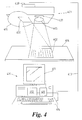
- Figure 4 of the accompanying drawings An alternative arrangement is illustrated in Figure 4 of the accompanying drawings. This differs from Figure 1 only in so far as the light source is within the field of view of the lens, and in that the processor combines the images in a different way. For clarity, the same reference numerals as used for Figure 1 have been used but incremented by 300.
- An optional shield 415 is also shown around the light source which prevents specular reflections due to ambient light occupying the same region of the first image as the specular reflections due to the light source.
- the second image may be captured at a longer exposure than the first image so that both captured images are fully exposed.
- the processor may combine the two images in the manner indicated in Figure 5 of the accompanying drawings,
- the processor After capturing 501 two images which are correctly exposed(i.e. neither under nor over exposed), the processor identifies 502 pixels in the first or the second image which correspond to specular reflected light from either the controlled light source or the ambient source. This identification can be performed simply by looking for bright spots in the images (which may even be saturated in many cases).
- the final image is constructed 503 by combining the two images such that any pixels identified as glare spots in the first image are replaced by corresponding pixels in the second image.
- the replacement or pasting of pixels is continued for the whole image until all the specular areas have been replaced.
- the pixels around the saturated points may also be blended 505 together to provide a smooth transition from the original areas to the replaced areas. Once all have been replaced 505 the process is ended 506 and the final image stored in the memory 111.
- a third image obtained using only ambient light and at the same exposure as the first image can be captured. This image is then processed with the first image as set out in Figure 2 prior to replacing the specular pixels in the (processed) first image with data values from the second image.
- the processor may compare the data in the first image and the second image to construct a map or transform which compensates for differences in colour temperature between the ambient light and the controlled light source.
- This colour transform can be calculated for regions of the image where pixels do not need to be replaced. Whenever a pixel is replaced in the first image the new pixel taken from the correctly exposed ambient image is passed through the colour transform before it is pasted into the final image.
- a transform may also be used to ensure that any misalignment between the images is removed prior to pasting in the replacement pixels. This is achieved by identifying the location of features in each image and mapping the features in the second image onto the features of the first image.
- FIG. 6 of the accompanying drawings A third embodiment of the present invention is illustrated in Figure 6 of the accompanying drawings. This differs from Figure 1 only in so far as the two identical light sources 606a and 606b are provided within the field of view of the lens. For clarity, the same reference numerals as used for Figure 1 have been used but incremented by 500.
- the read-out circuit captures a first image of the document illuminated by the first light source and a second image captured when the document is illuminated by the second light source.
- An additional ambient image is also captured in which the first and second light sources are extinguished so that the only source of illumination is the ambient light.
- the exposure times of the first and second images are chosen so that the images are fully exposed.
- the ambient image is captured with the same exposure as the first two images ( and is consequently underexposed).
- the ambient image is subtracted from each of the first and second captured images to produce respective first and second processed captured images.
- the effect of ambient light will have been removed from these processed images.
- points of glare in the first image are identified and are replaced by corresponding data values taken from the second processed image to form the final image.
- the two light sources are not identical (i.e. illuminate the document at different intensities) the exposure required for each of the first and second images will be different.
- two ambient images may be captured. A first one should be taken at the same exposure as the first captured image and the second at the same exposure as the second captured image.
Landscapes
- Engineering & Computer Science (AREA)
- Multimedia (AREA)
- Signal Processing (AREA)
- Studio Devices (AREA)
- Facsimile Scanning Arrangements (AREA)
- Image Input (AREA)
Applications Claiming Priority (2)
| Application Number | Priority Date | Filing Date | Title |
|---|---|---|---|
| GB0103828A GB2372391A (en) | 2001-02-16 | 2001-02-16 | Removal of specular reflection |
| GB0103828 | 2001-02-16 |
Publications (2)
| Publication Number | Publication Date |
|---|---|
| EP1233606A2 true EP1233606A2 (de) | 2002-08-21 |
| EP1233606A3 EP1233606A3 (de) | 2004-03-31 |
Family
ID=9908880
Family Applications (1)
| Application Number | Title | Priority Date | Filing Date |
|---|---|---|---|
| EP20020250812 Withdrawn EP1233606A3 (de) | 2001-02-16 | 2002-02-06 | Digitale Kamera |
Country Status (3)
| Country | Link |
|---|---|
| US (2) | US20020113882A1 (de) |
| EP (1) | EP1233606A3 (de) |
| GB (1) | GB2372391A (de) |
Cited By (13)
| Publication number | Priority date | Publication date | Assignee | Title |
|---|---|---|---|---|
| GB2405045A (en) * | 2003-08-08 | 2005-02-16 | Hewlett Packard Development Co | Improving digital images |
| EP1858242A1 (de) * | 2006-05-15 | 2007-11-21 | Brother Kogyo Kabushiki Kaisha | Bildlesevorrichtung mit Flachbettscanner, zur Detektion der Anwesenheit von Umgebungslicht. |
| WO2008078153A1 (en) * | 2006-12-22 | 2008-07-03 | Nokia Corporation | Removal of artifacts in flash images |
| WO2009029772A1 (en) * | 2007-08-29 | 2009-03-05 | Scientific Games International, Inc. | Enhanced scanner design |
| EP2115521A4 (de) * | 2007-01-26 | 2010-05-26 | Microsoft Corp | Abwechseln von lichtquellen zur verringerung der spiegelnden reflexion |
| EP1919187A3 (de) * | 2006-10-31 | 2010-07-14 | Hewlett-Packard Development Company, L.P. | Bildverarbeitungssystem und -verfahren |
| EP1856651A4 (de) * | 2005-01-26 | 2010-08-04 | Datalogic Scanning Inc | Datenlesegerät und verfahren zur abbildung von targets unter spiegelreflexion |
| US8519952B2 (en) | 2005-08-31 | 2013-08-27 | Microsoft Corporation | Input method for surface of interactive display |
| US8670632B2 (en) | 2004-06-16 | 2014-03-11 | Microsoft Corporation | System for reducing effects of undesired signals in an infrared imaging system |
| EP2661872A4 (de) * | 2011-01-04 | 2015-11-25 | Piqx Imaging Pte Ltd | Abtastverfahren und -vorrichtung |
| WO2018119345A1 (en) * | 2016-12-23 | 2018-06-28 | Lumileds Llc | Compensating for vignetting |
| KR20190099044A (ko) * | 2016-12-23 | 2019-08-23 | 루미레즈 엘엘씨 | 비네팅에 대한 보상 |
| EP2702756B1 (de) * | 2011-04-29 | 2022-06-08 | Optelec Holding B.V. | Tragbare kamera |
Families Citing this family (74)
| Publication number | Priority date | Publication date | Assignee | Title |
|---|---|---|---|---|
| GB2375676A (en) | 2001-05-17 | 2002-11-20 | Hewlett Packard Co | Reducing the effects of specular reflections appearing in an image |
| JP4451583B2 (ja) * | 2001-12-27 | 2010-04-14 | 富士フイルム株式会社 | 撮像装置、撮像方法、及びプログラム |
| US6792205B2 (en) * | 2002-04-17 | 2004-09-14 | Mitsubishi Electric Research Laboratories, Inc. | Method for generating a textured range image |
| US7102683B2 (en) * | 2002-04-17 | 2006-09-05 | Mitsubishi Electric Research Laboratories, Inc. | Single lens 3D camera |
| US7206023B2 (en) * | 2002-12-13 | 2007-04-17 | Belliveau Richard S | Image projection lighting devices with projection field light intensity uniformity adjustment |
| US7889275B2 (en) * | 2003-01-28 | 2011-02-15 | Microsoft Corp. | System and method for continuous flash |
| US20040208376A1 (en) * | 2003-04-18 | 2004-10-21 | Winbond Electronics Corp. | Pattern recognition device and method |
| US20050030392A1 (en) * | 2003-08-07 | 2005-02-10 | Kujin Lee | Method for eliminating blooming streak of acquired image |
| JP4416550B2 (ja) * | 2004-03-29 | 2010-02-17 | 富士フイルム株式会社 | ディジタル・スチル・カメラおよびその制御方法 |
| US20050276508A1 (en) * | 2004-06-15 | 2005-12-15 | Lockheed Martin Corporation | Methods and systems for reducing optical noise |
| US7443443B2 (en) * | 2005-07-28 | 2008-10-28 | Mitsubishi Electric Research Laboratories, Inc. | Method and apparatus for enhancing flash and ambient images |
| US7630002B2 (en) * | 2007-01-05 | 2009-12-08 | Microsoft Corporation | Specular reflection reduction using multiple cameras |
| US20070183688A1 (en) * | 2006-02-03 | 2007-08-09 | Gary Hollfelder | Data management system and method |
| JP4316629B2 (ja) * | 2007-03-29 | 2009-08-19 | 株式会社東芝 | 画像処理システム、画像取得方法及びプログラム |
| US8736751B2 (en) * | 2008-08-26 | 2014-05-27 | Empire Technology Development Llc | Digital presenter for displaying image captured by camera with illumination system |
| JP4623178B2 (ja) * | 2008-09-18 | 2011-02-02 | ソニー株式会社 | 画像信号処理装置、画像信号処理方法、プログラム、撮像装置および撮像システム |
| US8295635B2 (en) * | 2008-11-06 | 2012-10-23 | Bausch & Lomb Incorporated | Methods and apparatus for facilitating elimination of ambient light from an image |
| US10015380B2 (en) * | 2008-12-22 | 2018-07-03 | Ncr Corporation | Imaging system |
| EP2339534A1 (de) * | 2009-11-18 | 2011-06-29 | Panasonic Corporation | Spiegelreflektionskompensierung |
| JP2011114558A (ja) * | 2009-11-26 | 2011-06-09 | Fujifilm Corp | 撮像装置及び撮像方法 |
| US8339508B2 (en) * | 2010-02-22 | 2012-12-25 | Csr Technology Inc. | Method and apparatus for low-light imaging enhancement |
| US7991281B1 (en) * | 2010-03-19 | 2011-08-02 | Hewlett-Packard Development Company, L.P. | Illumination source having programmable rise and fall times |
| US8730384B2 (en) | 2010-06-03 | 2014-05-20 | Apple Inc. | Systems, methods, and devices for flash exposure control using preflash statistics |
| JP5141733B2 (ja) * | 2010-08-18 | 2013-02-13 | カシオ計算機株式会社 | 撮像装置、撮像方法、及びプログラム |
| TWI423657B (zh) * | 2011-01-25 | 2014-01-11 | Pixart Imaging Inc | 影像系統及其干擾消除方法 |
| US9516238B2 (en) * | 2011-02-10 | 2016-12-06 | Hewlett-Packard Development Company, L.P. | Noise suppression |
| US8730356B2 (en) * | 2011-03-07 | 2014-05-20 | Sony Corporation | System and method for automatic flash removal from images |
| US8755627B2 (en) * | 2011-04-14 | 2014-06-17 | Lexmark International, Inc. | Method and system for reducing speckles in a captured image |
| US20120268626A1 (en) * | 2011-04-25 | 2012-10-25 | Avermedia Information, Inc. | Apparatus and method for eliminating glare |
| US20130057664A1 (en) * | 2011-09-01 | 2013-03-07 | Cssn Inc. | Camera-based imaging devices, having alternating clusters of light sources, facilitated to eliminate hot spots |
| US9354748B2 (en) | 2012-02-13 | 2016-05-31 | Microsoft Technology Licensing, Llc | Optical stylus interaction |
| US9075566B2 (en) | 2012-03-02 | 2015-07-07 | Microsoft Technoogy Licensing, LLC | Flexible hinge spine |
| US9134807B2 (en) | 2012-03-02 | 2015-09-15 | Microsoft Technology Licensing, Llc | Pressure sensitive key normalization |
| US9870066B2 (en) | 2012-03-02 | 2018-01-16 | Microsoft Technology Licensing, Llc | Method of manufacturing an input device |
| US20130300590A1 (en) | 2012-05-14 | 2013-11-14 | Paul Henry Dietz | Audio Feedback |
| JP6138779B2 (ja) * | 2012-06-20 | 2017-05-31 | 株式会社日立製作所 | 自動画像合成装置 |
| US20140043492A1 (en) * | 2012-08-07 | 2014-02-13 | Siemens Corporation | Multi-Light Source Imaging For Hand Held Devices |
| US8964379B2 (en) | 2012-08-20 | 2015-02-24 | Microsoft Corporation | Switchable magnetic lock |
| US9912847B1 (en) | 2012-09-25 | 2018-03-06 | Amazon Technologies, Inc. | Image capture guidance to reduce specular reflection effects |
| TWI489090B (zh) * | 2012-10-31 | 2015-06-21 | Pixart Imaging Inc | 偵測系統 |
| US8786767B2 (en) | 2012-11-02 | 2014-07-22 | Microsoft Corporation | Rapid synchronized lighting and shuttering |
| US9307148B1 (en) | 2013-05-15 | 2016-04-05 | Amazon Technologies, Inc. | Video enhancement techniques |
| DE102013106556A1 (de) * | 2013-06-24 | 2014-12-24 | Qioptiq Photonics Gmbh & Co. Kg | Verfahren zum Betreiben einer Dentalkamera |
| US9852519B2 (en) | 2013-06-25 | 2017-12-26 | Pixart Imaging Inc. | Detection system |
| CN104376545B (zh) * | 2013-08-16 | 2018-12-14 | 联想(北京)有限公司 | 一种信息处理的方法及一种电子设备 |
| US9275448B2 (en) * | 2013-08-27 | 2016-03-01 | Xerox Corporation | Flash/no-flash imaging for binarization |
| JP5787964B2 (ja) * | 2013-11-15 | 2015-09-30 | 株式会社Pfu | 撮像システム及び画像データ生成方法 |
| JP5841587B2 (ja) * | 2013-12-25 | 2016-01-13 | 株式会社Pfu | 撮像システム |
| US9396571B2 (en) | 2014-02-10 | 2016-07-19 | International Business Machines Corporation | Simplified lighting compositing |
| US10120420B2 (en) | 2014-03-21 | 2018-11-06 | Microsoft Technology Licensing, Llc | Lockable display and techniques enabling use of lockable displays |
| CN104023179B (zh) * | 2014-06-27 | 2017-08-15 | 北京智谷睿拓技术服务有限公司 | 成像控制方法和设备 |
| US9769392B1 (en) * | 2014-06-27 | 2017-09-19 | Amazon Technologies, Inc. | Imaging system for addressing specular reflection |
| JP6379811B2 (ja) * | 2014-07-30 | 2018-08-29 | カシオ計算機株式会社 | 表示装置、表示制御方法及び表示制御プログラム |
| US10324733B2 (en) | 2014-07-30 | 2019-06-18 | Microsoft Technology Licensing, Llc | Shutdown notifications |
| US9667880B2 (en) * | 2014-08-22 | 2017-05-30 | Qualcomm Incorporated | Activating flash for capturing images with text |
| US12401911B2 (en) | 2014-11-07 | 2025-08-26 | Duelight Llc | Systems and methods for generating a high-dynamic range (HDR) pixel stream |
| US12401912B2 (en) | 2014-11-17 | 2025-08-26 | Duelight Llc | System and method for generating a digital image |
| JP6515637B2 (ja) * | 2015-03-30 | 2019-05-22 | 富士ゼロックス株式会社 | 画像読取装置および画像形成装置 |
| US12445736B2 (en) | 2015-05-01 | 2025-10-14 | Duelight Llc | Systems and methods for generating a digital image |
| TWI531984B (zh) | 2015-05-26 | 2016-05-01 | 原相科技股份有限公司 | 影像處理方法以及影像處理裝置 |
| US10298864B2 (en) | 2016-06-10 | 2019-05-21 | Apple Inc. | Mismatched foreign light detection and mitigation in the image fusion of a two-camera system |
| US10627494B2 (en) | 2016-09-16 | 2020-04-21 | Analog Devices, Inc. | Interference handling in time-of-flight depth sensing |
| US10713520B2 (en) | 2016-10-27 | 2020-07-14 | Engineering Innovation, Inc. | Method of taking a picture without glare |
| KR102669154B1 (ko) * | 2016-11-30 | 2024-05-28 | 삼성디스플레이 주식회사 | 패터닝 장치 및 이의 구동 방법 |
| US10309908B2 (en) * | 2017-01-11 | 2019-06-04 | Applied Vision Corporation | Light field illumination container inspection system |
| US10899138B2 (en) | 2017-01-11 | 2021-01-26 | Applied Vision Corporation | Container inspection system controlling printheads to correct for detected ink thickness errors |
| CN107872663B (zh) * | 2017-12-25 | 2019-05-24 | Oppo广东移动通信有限公司 | 图像处理方法及装置、计算机可读存储介质和计算机设备 |
| US10733469B2 (en) * | 2017-12-29 | 2020-08-04 | Idemia Identity & Security USA LLC | Capturing digital images of documents |
| US10742892B1 (en) * | 2019-02-18 | 2020-08-11 | Samsung Electronics Co., Ltd. | Apparatus and method for capturing and blending multiple images for high-quality flash photography using mobile electronic device |
| US10972638B1 (en) * | 2019-08-23 | 2021-04-06 | Zoox, Inc. | Glare correction in sensors |
| EP3820138A1 (de) * | 2019-11-06 | 2021-05-12 | Koninklijke Philips N.V. | System zur durchführung einer bildbewegungskompensation |
| US11430094B2 (en) | 2020-07-20 | 2022-08-30 | Samsung Electronics Co., Ltd. | Guided multi-exposure image fusion |
| CN114202910A (zh) * | 2020-08-28 | 2022-03-18 | 京东方科技集团股份有限公司 | 仪表识别装置、仪表监控系统及其监控方法 |
| US20230196527A1 (en) * | 2021-12-22 | 2023-06-22 | Paypal, Inc. | Removing Clarity Issues From Images To Improve Readability |
Citations (2)
| Publication number | Priority date | Publication date | Assignee | Title |
|---|---|---|---|---|
| US5969372A (en) | 1997-10-14 | 1999-10-19 | Hewlett-Packard Company | Film scanner with dust and scratch correction by use of dark-field illumination |
| US6088612A (en) | 1997-04-04 | 2000-07-11 | Medtech Research Corporation | Method and apparatus for reflective glare removal in digital photography useful in cervical cancer detection |
Family Cites Families (16)
| Publication number | Priority date | Publication date | Assignee | Title |
|---|---|---|---|---|
| JPS62172859A (ja) * | 1986-01-27 | 1987-07-29 | Canon Inc | 画像読取り装置 |
| US4814630A (en) * | 1987-06-29 | 1989-03-21 | Ncr Corporation | Document illuminating apparatus using light sources A, B, and C in periodic arrays |
| JP3159465B2 (ja) * | 1991-05-17 | 2001-04-23 | 株式会社東芝 | 画像表示装置 |
| US6714665B1 (en) * | 1994-09-02 | 2004-03-30 | Sarnoff Corporation | Fully automated iris recognition system utilizing wide and narrow fields of view |
| US6278490B1 (en) * | 1996-05-23 | 2001-08-21 | Olympus Optical Co., Ltd. | Exposure control for an image pickup apparatus that uses an electronic flash |
| JPH1051727A (ja) * | 1996-07-30 | 1998-02-20 | Nec Corp | 連写式デジタルカメラの画像記憶再生方法およびその装置 |
| US6021210A (en) * | 1997-12-01 | 2000-02-01 | Sensar, Inc. | Image subtraction to remove ambient illumination |
| US6061092A (en) * | 1997-12-05 | 2000-05-09 | Intel Corporation | Method and apparatus for dark frame cancellation for CMOS sensor-based tethered video peripherals |
| US6744471B1 (en) * | 1997-12-05 | 2004-06-01 | Olympus Optical Co., Ltd | Electronic camera that synthesizes two images taken under different exposures |
| EP0930498A3 (de) * | 1997-12-26 | 1999-11-17 | Nidek Co., Ltd. | Prüfeinrichtung und Verfahren zum Erfassen von Fehlstellen |
| JPH11252451A (ja) * | 1998-02-27 | 1999-09-17 | Canon Inc | 撮像装置及びコンピュータ読み取り可能な記憶媒体 |
| US6211913B1 (en) * | 1998-03-23 | 2001-04-03 | Sarnoff Corporation | Apparatus and method for removing blank areas from real-time stabilized images by inserting background information |
| WO2001028226A1 (en) * | 1999-10-08 | 2001-04-19 | Applied Science Fiction | Method and apparatus for differential illumination image-capturing and defect handling |
| GB2356996A (en) * | 1999-12-03 | 2001-06-06 | Hewlett Packard Co | Improvements to digital cameras |
| US6965460B1 (en) * | 2000-08-08 | 2005-11-15 | Hewlett-Packard Development Company, L.P. | Method and system for scanning an image using a look-down linear array scanner |
| GB2375676A (en) * | 2001-05-17 | 2002-11-20 | Hewlett Packard Co | Reducing the effects of specular reflections appearing in an image |
-
2001
- 2001-02-16 GB GB0103828A patent/GB2372391A/en not_active Withdrawn
-
2002
- 2002-02-06 EP EP20020250812 patent/EP1233606A3/de not_active Withdrawn
- 2002-02-15 US US10/075,300 patent/US20020113882A1/en not_active Abandoned
-
2005
- 2005-10-13 US US11/248,156 patent/US7619664B2/en not_active Expired - Fee Related
Patent Citations (2)
| Publication number | Priority date | Publication date | Assignee | Title |
|---|---|---|---|---|
| US6088612A (en) | 1997-04-04 | 2000-07-11 | Medtech Research Corporation | Method and apparatus for reflective glare removal in digital photography useful in cervical cancer detection |
| US5969372A (en) | 1997-10-14 | 1999-10-19 | Hewlett-Packard Company | Film scanner with dust and scratch correction by use of dark-field illumination |
Cited By (26)
| Publication number | Priority date | Publication date | Assignee | Title |
|---|---|---|---|---|
| GB2405045A (en) * | 2003-08-08 | 2005-02-16 | Hewlett Packard Development Co | Improving digital images |
| US8670632B2 (en) | 2004-06-16 | 2014-03-11 | Microsoft Corporation | System for reducing effects of undesired signals in an infrared imaging system |
| EP1856651A4 (de) * | 2005-01-26 | 2010-08-04 | Datalogic Scanning Inc | Datenlesegerät und verfahren zur abbildung von targets unter spiegelreflexion |
| US8519952B2 (en) | 2005-08-31 | 2013-08-27 | Microsoft Corporation | Input method for surface of interactive display |
| EP1858242A1 (de) * | 2006-05-15 | 2007-11-21 | Brother Kogyo Kabushiki Kaisha | Bildlesevorrichtung mit Flachbettscanner, zur Detektion der Anwesenheit von Umgebungslicht. |
| US8279497B2 (en) | 2006-05-15 | 2012-10-02 | Brother Kogyo Kabushiki Kaisha | Image-reading device performing shading correction based on white reference data |
| US8218202B2 (en) | 2006-10-31 | 2012-07-10 | Hewlett-Packard Development Company, L.P. | Multiple image combination via comparative data transform and normalization transform application |
| EP1919187A3 (de) * | 2006-10-31 | 2010-07-14 | Hewlett-Packard Development Company, L.P. | Bildverarbeitungssystem und -verfahren |
| US8442349B2 (en) | 2006-12-22 | 2013-05-14 | Nokia Corporation | Removal of artifacts in flash images |
| WO2008078153A1 (en) * | 2006-12-22 | 2008-07-03 | Nokia Corporation | Removal of artifacts in flash images |
| CN101563913B (zh) * | 2006-12-22 | 2011-10-19 | 诺基亚公司 | 消除闪光灯图像中的赝像 |
| US20100278452A1 (en) * | 2006-12-22 | 2010-11-04 | Nokia Corporation | Removal of Artifacts in Flash Images |
| US8212857B2 (en) | 2007-01-26 | 2012-07-03 | Microsoft Corporation | Alternating light sources to reduce specular reflection |
| EP2115521A4 (de) * | 2007-01-26 | 2010-05-26 | Microsoft Corp | Abwechseln von lichtquellen zur verringerung der spiegelnden reflexion |
| WO2009029772A1 (en) * | 2007-08-29 | 2009-03-05 | Scientific Games International, Inc. | Enhanced scanner design |
| US8199370B2 (en) | 2007-08-29 | 2012-06-12 | Scientific Games International, Inc. | Enhanced scanner design |
| US8638479B2 (en) | 2007-08-29 | 2014-01-28 | Scientific Games International, Inc. | Enhanced scanner design |
| CN101883614A (zh) * | 2007-08-29 | 2010-11-10 | 科学游戏控股有限公司 | 提高的扫描设备设计 |
| CN101883614B (zh) * | 2007-08-29 | 2014-04-02 | 科学游戏控股有限公司 | 一种改进的扫描设备 |
| EP2661872A4 (de) * | 2011-01-04 | 2015-11-25 | Piqx Imaging Pte Ltd | Abtastverfahren und -vorrichtung |
| EP2702756B1 (de) * | 2011-04-29 | 2022-06-08 | Optelec Holding B.V. | Tragbare kamera |
| WO2018119345A1 (en) * | 2016-12-23 | 2018-06-28 | Lumileds Llc | Compensating for vignetting |
| KR20190099044A (ko) * | 2016-12-23 | 2019-08-23 | 루미레즈 엘엘씨 | 비네팅에 대한 보상 |
| US10582169B2 (en) | 2016-12-23 | 2020-03-03 | Lumileds Llc | Compensating for vignetting |
| US10893244B2 (en) | 2016-12-23 | 2021-01-12 | Lumileds Llc | Compensating for vignetting |
| CN113329140A (zh) * | 2016-12-23 | 2021-08-31 | 亮锐有限责任公司 | 补偿渐晕 |
Also Published As
| Publication number | Publication date |
|---|---|
| US20060033835A1 (en) | 2006-02-16 |
| EP1233606A3 (de) | 2004-03-31 |
| GB0103828D0 (en) | 2001-04-04 |
| US7619664B2 (en) | 2009-11-17 |
| US20020113882A1 (en) | 2002-08-22 |
| GB2372391A (en) | 2002-08-21 |
Similar Documents
| Publication | Publication Date | Title |
|---|---|---|
| US7619664B2 (en) | Digital image capture apparatus and method for obtaining a digital image of an object | |
| JP4083042B2 (ja) | 画像読取り装置,画像読取り方法 | |
| WO2016147524A1 (ja) | 画像読取装置 | |
| JP4236958B2 (ja) | 画像読取り装置,画像読取り方法 | |
| JP2002330336A (ja) | 画像捕捉装置および方法 | |
| JP2001268323A (ja) | 画像入力装置 | |
| EP0853424A2 (de) | Getrennte Farbtontabellen | |
| US8649076B2 (en) | Calibrating field uniformity | |
| JP2001169055A (ja) | スキャナの照明システムおよびその操作方法 | |
| JP3087684B2 (ja) | 画像読取装置 | |
| JP2016032219A (ja) | 画像読取装置、画像形成装置及び画像読取方法 | |
| US5822052A (en) | Method and apparatus for compensating illuminance error of a light source | |
| GB2376369A (en) | Scanner illumination compensation | |
| JP2924746B2 (ja) | 画像読取り装置 | |
| US8179573B2 (en) | Scanning two images of media | |
| JPH08172506A (ja) | 画像読取装置 | |
| JPH10136349A (ja) | テレビドアホン装置の焦点調節方法 | |
| JP3405062B2 (ja) | フィルム画像読取装置 | |
| US7262888B2 (en) | Optical scanner apparatus with pinhole imaging device | |
| JPH11331686A (ja) | 画像入力装置 | |
| US20040119417A1 (en) | Scanner with common illumination light source | |
| JP6919460B2 (ja) | 画像読取装置、画像形成装置および画像読取方法 | |
| KR100401172B1 (ko) | 씨씨디용 조도 광대역 촬영 수단 | |
| JPH01213066A (ja) | 原稿移動型画像読取装置 | |
| JPH1155461A (ja) | 照度調節撮像方式および画像撮像装置 |
Legal Events
| Date | Code | Title | Description |
|---|---|---|---|
| PUAI | Public reference made under article 153(3) epc to a published international application that has entered the european phase |
Free format text: ORIGINAL CODE: 0009012 |
|
| AK | Designated contracting states |
Kind code of ref document: A2 Designated state(s): AT BE CH CY DE DK ES FI FR GB GR IE IT LI LU MC NL PT SE TR |
|
| AX | Request for extension of the european patent |
Free format text: AL;LT;LV;MK;RO;SI |
|
| PUAL | Search report despatched |
Free format text: ORIGINAL CODE: 0009013 |
|
| AK | Designated contracting states |
Kind code of ref document: A3 Designated state(s): AT BE CH CY DE DK ES FI FR GB GR IE IT LI LU MC NL PT SE TR |
|
| AX | Request for extension of the european patent |
Extension state: AL LT LV MK RO SI |
|
| 17P | Request for examination filed |
Effective date: 20040513 |
|
| AKX | Designation fees paid |
Designated state(s): DE FR GB |
|
| RAP1 | Party data changed (applicant data changed or rights of an application transferred) |
Owner name: HEWLETT-PACKARD DEVELOPMENT COMPANY, L.P. |
|
| STAA | Information on the status of an ep patent application or granted ep patent |
Free format text: STATUS: THE APPLICATION IS DEEMED TO BE WITHDRAWN |
|
| 18D | Application deemed to be withdrawn |
Effective date: 20150929 |