EP1234278B1 - Systeme et procede permettant de corriger une image mosaique creee a partir d'images enregistrees par une camera mobile - Google Patents
Systeme et procede permettant de corriger une image mosaique creee a partir d'images enregistrees par une camera mobile Download PDFInfo
- Publication number
- EP1234278B1 EP1234278B1 EP00969744A EP00969744A EP1234278B1 EP 1234278 B1 EP1234278 B1 EP 1234278B1 EP 00969744 A EP00969744 A EP 00969744A EP 00969744 A EP00969744 A EP 00969744A EP 1234278 B1 EP1234278 B1 EP 1234278B1
- Authority
- EP
- European Patent Office
- Prior art keywords
- image
- individual image
- points
- vertical anchor
- vertical
- Prior art date
- Legal status (The legal status is an assumption and is not a legal conclusion. Google has not performed a legal analysis and makes no representation as to the accuracy of the status listed.)
- Expired - Lifetime
Links
Images





Classifications
-
- G—PHYSICS
- G06—COMPUTING OR CALCULATING; COUNTING
- G06T—IMAGE DATA PROCESSING OR GENERATION, IN GENERAL
- G06T3/00—Geometric image transformations in the plane of the image
- G06T3/40—Scaling of whole images or parts thereof, e.g. expanding or contracting
- G06T3/4038—Image mosaicing, e.g. composing plane images from plane sub-images
-
- H—ELECTRICITY
- H04—ELECTRIC COMMUNICATION TECHNIQUE
- H04N—PICTORIAL COMMUNICATION, e.g. TELEVISION
- H04N23/00—Cameras or camera modules comprising electronic image sensors; Control thereof
- H04N23/60—Control of cameras or camera modules
- H04N23/698—Control of cameras or camera modules for achieving an enlarged field of view, e.g. panoramic image capture
-
- H—ELECTRICITY
- H04—ELECTRIC COMMUNICATION TECHNIQUE
- H04N—PICTORIAL COMMUNICATION, e.g. TELEVISION
- H04N5/00—Details of television systems
- H04N5/222—Studio circuitry; Studio devices; Studio equipment
- H04N5/262—Studio circuits, e.g. for mixing, switching-over, change of character of image, other special effects ; Cameras specially adapted for the electronic generation of special effects
- H04N5/2628—Alteration of picture size, shape, position or orientation, e.g. zooming, rotation, rolling, perspective, translation
Definitions
- the invention relates generally to the field of generating mosaic images and more particularly to generating a rectified mosaic image from a series of images recorded by a moving camera.
- mosaicing of images a number of overlapping images of a scene are initially recorded by a camera. Using information in the regions in which the images overlap, a single image is generated which has, for example, a wider field of view of the scene than might be possible otherwise.
- mosaic images are generated in connection with a plurality of individual images that are recorded by a camera that is rotated around a stationary optical axis. Such mosaic images provide a panoramic view around the optical axis.
- mosaic images are generated from images recorded by, for example, an aerial camera, translating parallel to the scene and the optical axis is perpendicular both to the scene and to the direction of camera motion.
- the image contents will generally expand from frame to frame, as the camera gets closer to the objects in sight.
- the second image is warped so that corresponding points will match the first image
- the size of the second image will shrink, resulting in a mosaic that tapers from left to right.
- the camera is pointed backward from the direction of motion
- the image contents generally shrink from frame to frame.
- the second image is warped so that corresponding points will match the first image
- the size of the second image will increase, resulting in a mosaic whose dimensions increase from left to right.
- the invention is defined by the appended claims and provides a new and improved system and method for generating a rectified mosaic image from a series of images recorded by a moving camera.
- the invention provides a system and method for generating a rectified mosaic image from a plurality of individual images, the system comprising a quadrangular region defining module, a warping module and a mosaicing module.
- the quadrangular region defining module is configured to define in one individual image a quadrangular region in relation to two points on a vertical anchor in the one individual image and mappings of two points on a vertical anchor in at least one other individual image into the one individual image wherein each vertical anchor is a vertical image feature that remains invariant under the warping of the quadrangular region of its respective image.
- the warping module is configured to warp the quadrangular region to a rectangular region.
- the mosaicing module configured to mosaic the quadrangular region to the mosaic image.
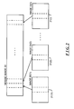
- FIG. 1 schematically depicts a system 10 for generating a mosaic image from a series of images recorded by a moving camera, constructed in accordance with the invention.
- system 10 includes a camera 11 that is mounted on a rig 12.
- the camera 11 may be any type of camera for recording images on any type of recording medium, including, for example, film, an electronic medium such as charge-coupled devices (CCD), or any other medium capable of recording images.
- the rig 12 facilitates pointing of the camera 11 at a scene 13 to facilitate recording of images thereof.
- the rig 12 includes a motion control 14 configured to move the camera 11. In moving the camera 11, the motion control can translate the camera 11, rotate it around its axis, or any combination thereof.
- the motion control 14 can translate the camera 11 along a path 16 and rotate the camera during translation. While the camera 11 is being moved, it can record images 20(1),..., 20(I) (generally identified by reference numeral 20(i)) of the scene 13 from a series of successive locations along the path 16. The individual images recorded at the successive locations are provided to an image processor 17 for processing into a unitary mosaic image, as will be generally described in connection with FIG. 2 . Preferably the successive images 20(i) will overlap, which will facilitate generation of the mosaic image as described below.
- the image processor 17 processes the series of individual images to generate a unitary mosaic image. Operations performed by the image processor 17 in connection with that operation will generally be described in connection with FIG. 2 .
- the image processor 17 will initially receive two or more images 20(i). Thereafter the image processor 17 will process two individual images, for example, images 20(1) and 20(2) to find overlapping portions 21 (1) and 21(2) of the scene generally toward the right and left sides of the respective images 20(1) and 20(2), respectively, and use those corresponding portions 21(1) and 21(2) to align the images 20(1) and 20(2). Given the alignment, portions 21(1) and 21 (2) can be defined in images 20(1) and 20(2) such that they can be combined to form a portion of the mosaic image 22.
- FIGS. 3A through 3D Several problems arise in connection with generation of the mosaic image 21 as described above.
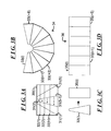
- One such problem will be described in connection with FIGS. 3A through 3D .
- the image processor 17 processes two successive individual images 20(1) and 20(2) to mosaic them together, or an individual image 20(i) (i>2) and the previously-generated mosaic image 22, it uses overlapping portions to align the respective images 20(1) and 20(2).
- the problem described in connection with FIGS. 3A through 3D arises when features that are used to align the individual images do not have a uniform image motion.
- planar surface that is tilted with respect to the camera 11, so that, for example, the planar surface is parallel to the path 16 along which the camera is translated, but tilted so that the lower portion of the planar surface is closer to the camera 11 and the upper portion of the planar surface farther away from the camera 11.
- the planar surface is provided with a series of equi-distant vertical lines.
- each of the individual images will appear as the image 30(i) depicted FIG. 3A , with the vertical lines appearing as slanted lines 31(1) through 31(S) (generally identified by reference numeral 31(s)). Since the lower part of the image 30(i) is of the portion of the planar surface that is closer to the camera 11, and the upper part of the image 30(i) is of the portion of the planar surface that is farther from the camera 11, the vertical lines on the planar surface will be recorded as the slanted lines 31(s).
- the perspective due to the tilting of the planar surface causes the lines that are to the left of the center of the image 30(i) to be slanted toward the right and the lines that are to the right of the center to be slanted toward the left in the image 30(i).
- the strength of the curl is, in the case of a rotating camera, a function of the angle between the viewing direction and the rotation axis, and, in the case of a translating camera, a function of the angle with which the planar surface is tilted with respect to the image plane of the camera 11.
- the problem described above in connection with FIGS. 3A and 3B can be corrected by rectifying the strips 33(i) as shown in FIG. 3C to provide successive rectangular strips 35(i), which, as shown in FIG. 3D , can be mosaiced together to provide a rectified mosaic image 36.
- the orientation of the planar surface relative to the image plane of the camera 11 is unknown, but the amount of distortion, if any, that is caused by the orientation can be determined from the optical flow, that is, the change of the position and orientation of respective vertical lines as between successive images.
- the image processor 17 can process each of the individual images to correct for the distortion prior to integrating them into the mosaic.
- FIGS. 4A through 4D Another problem will be described in connection with FIGS. 4A through 4D .
- the camera 11 is moving from left to right parallel to a vertical planar surface, and is tilted forward, that is, tilted to the right with respect to the planar surface.
- the planar surface is provided with lines running horizontally as well as vertically, and the camera is tilted with respect to the planar surface in such a manner that it points to the right.
- an image 50(i) recorded by the camera the vertical lines 51(1), 51(2),... will remain vertical, but the horizontal lines 52(1), 52(2),...
- line 51(S-1) in image 50(i) corresponds to line 51(2) in image 50(1+1).
- the strip in mosaicing a strip 53(i) from an image 50(i), the strip can be defined by vertical lines 51(2) and 51(S-1) on the left and right sides, and, for example, by lines 52(1) and 52(H) at the top and the bottom, in each image 50(i), 50(i+1),....
- the strip 53(i+1) in matching a strip 53(i+1) from image 50(i+1) to the left edge of a strip 53(i) from the preceding image 50(i), the strip 53(i+1) will be warped so that the respective horizontal lines 52(1), 52(2),...,52(H-1), 52(H) along the left edge of the strip 53(i) will match the same lines 52(1), 52(2),..., 52(H-1), 52(H) along the right edge of the strip 53(i+1). Accordingly, the mosaic image 54 formed from successive strips will taper from left to right. As shown in FIG. 4C , the image processor 17 can rectify this distortion by rectifying each strip 53(i), 53(i+1),...
- a third problem which generally is a combination of those described above in connection with FIGS. 3A through 3D and 4A through 4D , will be described in connection with FIGS. 5A through 5D .
- both the planar surface comprising the scene and the camera 11 recording images of the scene may be tilted.
- the planar surface in this case includes a plurality of vertical and horizontal lines. In that case, each image 60(i) as recorded by the camera will as shown in FIG.
- the vertical line 61(V-1) in image 60(i) corresponds to the same line in the scene 12 as line 61 (2) in image 60(i+ 1) when the image processor 17 mosaics strips from the successive images 60(i), 60(i+1),... it can select as the strip the region of each image bordered by vertical lines 61(1) and 61(2) and horizontal lines 62(1) and 62(H). In that case, if the strip 63(i) for the mosaic image 64 (reference FIG.
- each strip ..., 70(i-1), 70(i), 70(i+1),... in the mosaic image 71 is obtained from a respective strip ..., 72(i-1), 72(i), 72(i+1),... in successive images ..., 73(i-1), 73(i), 73(i+1),... recorded by the camera 11.
- the image processor 17 will need to define the borders of each strip 70(i) in the mosaic image 71, the borders of the regions in the respective images 73(i) that will comprise for the respective strips 72(i) and the mapping transformation from the strip 72(i) to the strip 70(i). To accomplish that, the image motion between successive pairs of images 73(i-1), 73(i) and 73(i), 73(i+1) is determined. Generally, for image 73(i), the image processor 17 defines the region that is to comprise the strip 72(i) to satisfy three conditions, namely:
- the rectangular strips ..., 70(i-1), 70(i), 70(i+1),,.. in the mosaic 71 have a uniform height to provide a mosaiced image 71 of uniform height and to avoid expanding or shrinking the mosaic image 71 vertically.
- the vertical location of the strip 70(i) in the mosaic image 71 changes according to the vertical motion or tilt of the camera 11.
- the width of the strip 70(i) is determined by the motion of the scene 12 from image to image.
- the image processor 17 obtains the strip as defined one side of an vertical anchor.
- the vertical anchor is a vertical feature in the image that remains invariant under the transformation that warps a strip in the image to a strip in the mosaic. Only transformations that keep the anchor invariant will be considered for warping a strip in the image to a strip in the mosaic.
- the vertical anchor may be anywhere in the image 73(i), illustratively, the center, the left border, or other column; in the embodiment described in connection with FIGS. 7 and 8 , the vertical anchor is selected to be the left border of the image 73(i), and that vertical anchor will also form the left border of the strip 70(i).
- the strip is defined on two sides of a vertical anchor, will be described below in connection with FIGS. 10 and 11 .
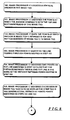
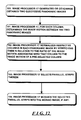
- the image processor 17 will initially locate the vertical anchor in the image 73(i) (step 100) and identify the points P k and Q k (where index "k” has the same value as index "i") at which the anchor intersects with the top and bottom borders of the image 73(i) (step 101). Using the homography H k -1 between images 73(i+1) and 73(i), the image processor also maps the points P k+1 and Q k+1 in image 73(i+1) to image 73(i) as points P - k and Q - k , respectively (step 102).
- the image processor 17 After the image processor 17 has located points P - k and Q - k , it identifies the line L k passing therethrough (step 103) and then identifies two points P' k and Q' k on the line such that the distance between them along the line L k is the same as the distance between points P - k and Q - k , and their centroid is in the middle row of the image (step 104).
- the image processor can determine the region of image 73(i) that is to be used as the strip 72(i) is the quadrilateral defined by points P' k , Q' k , Q k and P k (step 105) and warp the strip to rectangular form using a smooth (for example, bilinear) interpolation of the coordinates of those points, thereby to generate the strip 70(i) (step 106). It will be appreciated that the use of an interpolation is an approximation of the real transformation, which is unknown, but if the strip 72(i) is relatively narrow, the approximation will suffice. Thereafter, the image processor 17 can mosaic the strip 70(i) to the previously-generated mosaic image 71, if any (step 107).
- the image processor 17 will determine the vertical offset to be used for the next strip 70(i+1) (step 108). In that operation, the image processor will determine the vertical offset as ⁇ Q k ⁇ - Q ⁇ k ⁇ * h ⁇ Q ⁇ k - P ⁇ k ⁇ , where ⁇ A-B ⁇ refers to the distance between two points A and B and "h" is the image height.
- the vertical anchor may be any column in the image 73(i); in one embodiment it is selected to be the center column, since that will reduce lens distortion.
- the image processor identifies two regions, approximately symmetric on opposing sides of the center column, both of which be warped to form respective portions of the strip 70(i) to be used in the mosaic image 71.
- the image processor 17 will initially identify the vertical anchor in the image 73(i) (step 120) and identify the points P k and Q k at which the anchor intersects with the top and bottom borders of the image 73(i) (step 121).
- the image processor 17 will determine a value for "d," the vertical offset between the point Q k-1 that comprises the center of the image 73(i-1), that is, the projection of point Q k-1 in image 73, that is, H k-1 (Q k-1 ) (step 122), where H k-1 is the homography between image 73(i-1) and image 73(i), and identify two points P' k and Q' k which correspond to points P k and Q k shifted vertically by an amount corresponding to the value "d" (step 123).
- the image processor 17 will perform operations similar to steps 122 and 123 as between images 73(i) and 73(i+1) using the homography H k therebetween (step 124).
- the image processor 17, using the homography H k-1 maps the points P k-1 and Q k-1 to image 73(i) as points H k-1 (P k-1 ) and H k-1 (Q k-1 ), respectively (step 125), and, using the homography H k-1 , maps points P' k+1 and Q' k+1 to image 73(i) as points H -1 k (P' k+1 ) and H -1 k (Q k+1 ) (step 126).
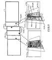
- the points H k-1 (P k-1 ), P' k , Q' k , and H k-1 (Q k-1 ) define a left quadrangular region 80(i)(L), and points P k , H -1 k (P k+1 ), H -1 k (Q k-1 ) and Q k define a right quadrangular region 80(i)(R), a portion of each of which will be used in generating respective rectangular portions 81 (i)(L) and 81 (i)(R) that together will be used as the strip for the image 73(i) in the mosaic image 71.
- right quadrangular region 80(i)(R), along with the left quadrangular region 80(i+1)(L) associated with the next image 73(i+1), in connection with the next rectangular region 81(j+1) in the mosaic image 71 The size and shape of the respective rectangular regions is somewhat arbitrary.
- the portion of quadrangular region 80(i)(L) that will be used in connection with the left-hand portion of strip 70(i) is the quadrangular region 82(i) defined by points A 11 , P' k , Q' k , and A 21 .
- points P k , H -1 k (P k+1 ), H -1 k (Q k-1 ) and Q k that define the right quadrangular region 80(i)(R) will also relate to the points defining the corners of the rectangular region 81(j+1), and it will be necessary to find the points A 12 and A 22 that relate to the mid-points of the top and bottom of the rectangular region 81 (j+1), respectively.
- the portion of quadrangular region 80(i)(R) that will be used in connection with the left-hand portion of strip 70(i) is the quadrangular region 83(i) defined by points P k , A 12. A 22 and Q k .
- the rectangular regions 81 (j) and 81 (j+1) can both be defined by points UVWX, with points U and V defining the left and right top corners, respectively, and points W and X defining the right and left bottom corners, respectively.
- the relationship between the left and right quadrangular regions 80(i)(L) and 80(i)(R) will be defined by respective homographies F L and F R .
- the camera 11 has been one that records images in a particular direction.
- the image processor 17 can also generate a mosaic of a plurality of panoramic images.
- a panoramic image is generated from a plurality of images recorded from a number of angular orientations around a common axis, which images are mosaiced together to provide a single panoramic image of the scene surrounding the axis.
- the panoramic image so generated is typically the full 360 degree circle surrounding the axis, or a substantial part thereof.
- the images that are used in generating the panoramic image may be recorded by a single camera that is rotated around the axis to facilitate recording of the images from the requisite plurality of angular orientations, or by a plurality of cameras disposed at the requisite angular orientations.
- a panoramic image can also be obtained by a single camera with a very wide field of view, which may be provided by a very wide angle lens, a combination of lenses and mirrors, or other arrangements as will be apparent to those skilled in the art.
- the panoramic image may be cylindrical or alternatively it may be flat.
- the images are recorded to facilitate generation of a plurality of panoramic images recorded at successive locations along the axis, with the panoramic images overlapping such that the image processor 17 can mosaic them together along the direction of the axis.
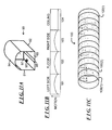
- FIG. 11A schematically depicts a train tunnel 90 having left and right sides 91 and 92, a floor 93 and a ceiling 94.
- the left and right sides 91 and 92 and the floor are planar surfaces, and the ceiling 94 is arched.
- a pair of tracks 95 is disposed on the floor to facilitate traversal of the tunnel by a train (not shown).
- a panoramic camera 96 comprising, for example, a plurality of individual cameras disposed around a common axis 97, which extends generally parallel to the length of the tunnel, records images along the axis from a plurality of angular orientations.
- the camera 96 is moved along the axis 97 to facilitate recording of images from which a series of panoramic images along the axis 97 can be generated, which series can be processed as described below in connection with FIG. 13, and the processed panoramic images 100(1), 100(2),... mosaiced together to form a single mosaic panoramic image 100 ( FIG. 11C ).
- the tunnel 90 comprises left and right sides 91 and 92, a floor 93 and a ceiling 94.
- the surface of the ceiling 94 is cylindrical with an axis corresponding to the axis 97.
- the distance from axis 97 to each of the left and right sides 91 and 92 and floor 93 is smallest at the center of the left and right sides and floor, and largest at the corners.
- the image motion that is, the apparent motion of features and objects in the images as between panoramic images will be as depicted in the graph depicted FIG. 11B .
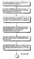
- the image processor 17, in generating a mosaic panoramic image 101 from the individual panoramic images 100(1), 100(2),..., will process the individual panoramic images to correct for the differences in the image motion. Operations performed by the image processor 17 in generating a mosaic panorama image 100 will be described in connection with the flow chart in FIG. 11 .
- the image processor 17 After the image processor 17 has generated or otherwise obtained two successive panoramic images 100(i), 100(i+1) that are to be mosaiced together (step 150), for each column it determines the image motion between the two panoramic images (step 151).
- the image motion as determined by the image processor 17 may have a motion profile similar to that described above in connection with FIG. 3 , with image motion of regions relatively close to the camera being relatively high and image motion of regions further away being relatively low.
- the image processor 17 normalizes respective columns in each panoramic image 100(i), 100(i+1) by stretching them in relation to the ratio of the image motion associated with that column to the image motion of a pre-selected column (step 152), each column comprising the series of picture elements in the direction parallel to the axis 97.
- the pre-selected column may be the column with the highest motion, or any other selected column in the panoramic image.
- the image processor 17 will leave at least one row or set of columns unchanged. If, for example, the image processor 17 does not normalize the columns of the portion of the panoramic image relating to the floor 91, in the resulting mosaic panoramic image the floor will appear to be flat and the ceiling 94 will appear to be curved.
- the image processor 17 does not normalize the columns of the portion of the panoramic image relating to the ceiling 94, in the resulting mosaic panoramic image the ceiling will appear to be flat and the floor will appear to be curved. Similarly, if the image processor does not normalize the columns of the portion of the panoramic image relating to the left and/or right sides, in the mosaic panoramic image the left and/or right sides will appear to be flat and both the ceiling and floor will appear to be curved.
- the image processor 17 After the image processor 17 has normalized the respective panoramic images 100(i), 100(i+1) (step 152), it will select parallel strips therein (step 153) and mosaic the parallel strips into the mosaic image 100 (step 154).
- the system provides a number of advantages.
- the system provides an arrangement that can generate mosaic images of scenes including tilted surfaces using a translated camera that is pointed toward the scene generally sideways.
- the camera may be translated in a direction that is parallel to the tilted surface and pointed directly thereat, that is, perpendicular to the translation direction (reference FIGS. 3A through 3D ).
- the camera may be pointed in a direction that is tilted with respect to the direction of motion (reference FIGS. 7A through 10 ).
- the system 10 can generate a mosaic of panoramic images (reference FIGS. 11A through 12 ) and in connection therewith can determine the shapes of surfaces in the mosaic images.
- the system 10 was described as generating a mosaic of panoramic images of a train tunnel, it will be appreciated that the system can generate such a mosaic panoramic image of a variety of kinds of scenes, including but not limited to water or sewer pipes, corridors and hallways, and the like.
- a system in accordance with the invention can be constructed in whole or in part from special purpose hardware or a general purpose computer system, or any combination thereof, any portion of which may be controlled by a suitable program.
- Any program may in whole or in part comprise part of or be stored on the system in a conventional manner, or it may in whole or in part be provided in to the system over a network or other mechanism for transferring information in a conventional manner.
- the system may be operated and/or otherwise controlled by means of information provided by an operator using operator input elements (not shown) which may be connected directly to the system or which may transfer the information to the system over a network or other mechanism for transferring information in a conventional manner.
Landscapes
- Engineering & Computer Science (AREA)
- Multimedia (AREA)
- Signal Processing (AREA)
- Physics & Mathematics (AREA)
- General Physics & Mathematics (AREA)
- Theoretical Computer Science (AREA)
- Image Processing (AREA)
- Studio Circuits (AREA)
- Studio Devices (AREA)
- Closed-Circuit Television Systems (AREA)
- Editing Of Facsimile Originals (AREA)
Claims (18)
- Système pour générer une image mosaïque à partir d'une pluralité d'images individuelles, comprenant:A. un module définissant une zone quadrangulaire, qui est adapté pour définir une zone quadrangulaire dans au moins une desdites images individuelles, qui n'est pas déjà rectangulaire par rapport à deux points sur une ancre verticale dans ladite une image individuelle et par rapport aux applications de deux points sur une ancre verticale dans au moins une autre image individuelle dans ladite une image individuelle,B. un module de déformation, qui est adapté pour déformer une zone quadrangulaire dans une zone rectangulaire, etC. un module de création de mosaïque, qui est adapté pour composer au moins les zones rectangulaires dans une image mosaïque, où chaque ancre verticale est une caractéristique d'image verticale, qui reste invariante sous la déformation de la zone quadrangulaire de son image respective.
- Système selon la revendication 1, où lesdits deux points sur ladite ancre verticale dans ladite une image individuelle comprennent des points, où l'ancre verticale coupe des limites supérieures et inférieures de ladite une image individuelle.
- Système selon la revendication 1, où le module de déformation est adapté pour interpoler d'une manière régulière entre ladite zone quadrangulaire et ladite zone rectangulaire.
- Système selon la revendication 1, où ledit module définissant la zone quadrangulaire comprend:A. un module identifiant un premier point d'ancre verticale, qui est adapté pour identifier deux points sur l'ancre verticale dans ladite une image individuelle,B. un module identifiant un deuxième point d'ancre verticale, qui est adapté pour identifier deux points dans ladite une image individuelle, où les deux points sont reproduits sur l'ancre verticale dans ladite au moins une autre image individuelle sur ladite une image individuelle,C. un module déterminant un premier segment de ligne, qui est adapté pour déterminer un segment de ligne entre les deux points dans ladite une image individuelle, où les deux points sont reproduits sur l'ancre verticale dans ladite au moins une autre image individuelle sur ladite une image individuelle, etD. un module déterminant un deuxième segment de ligne, qui est adapté pour déterminer un deuxième segment de ligne le long d'une ligne, qui est défini par le premier segment de ligne, où le deuxième segment de ligne est tel que la distance entre les points extrêmes correspond à la distance entre les points extrêmes du premier segment de ligne et est positionné le long de la ligne tel que le centre de gravité des points extrêmes du deuxième segment de ligne correspond au centre vertical de l'une image, la zone quadrangulaire correspondent aux deux points sur l'ancre verticale dans ladite une image individuelle et les points extrêmes dudit deuxième segment de ligne.
- Système selon la revendication 4, aussi comprenant un module qui génère une valeur d'offset verticale, qui est adapté pour générer une valeur d'offset pour une utilisation dans l'étape de création de mosaïque pour générer une zone quadrangulaire, qui a été produite pour ladite autre image individuelle.
- Système selon la revendication 1, où le module définissant la zone quadrangulaire est adapté pour définir deux zones quadrangulaires sur des faces opposées de l'ancre verticale, chacune par rapport aux applications de deux points sur une ancre verticale dans au moins deux autre images individuelles dans ladite une image individuelle.
- Système selon la revendication 6, où le module définissant la zone quadrangulaire est adapté pour définir une zone quadrangulaire à gauche par rapport (i) aux applications des deux points sur l'ancre verticale dans une image individuelle de gauche dans ladite une image individuelle, et (ii) des deux points sur l'ancre verticale dans ladite une image individuelle, déplacés d'une manière verticale par rapport à un offset vertical entre le centre de l'une image individuelle et l'application du centre de l'image individuelle de gauche sur ladite une image individuelle.
- Système selon la revendication 6, où le module définissant la zone quadrangulaire est adapté pour définir une zone quadrangulaire à droite par rapport (i) aux applications des deux points sur l'ancre verticale dans une image individuelle à gauche dans ladite une image individuelle et (ii) pour lesdits deux points sur l'ancre verticale dans ladite une image individuelle.
- Procédé mise en oeuvre dans un ordinateur pour générer une image mosaïque d'une pluralité d'images individuelles, comprenant les étapes:A. une étape définissant une zone quadrangulaire, dans laquelle dans une image individuelle une zone quadrangulaire, qui n'est pas déjà rectangulaire, par rapport aux deux points sur une ancre verticale dans ladite une image individuelle et par rapport aux applications des deux points sur une ancre verticale dans au moins une autre image individuelle dans ladite une image individuelle,B. une étape de déformation, dans laquelle la zone quadrangulaire est déformée dans une zone rectangulaire, etC. une étape de création d'une mosaïque, dans laquelle au moins la zone rectangulaire est composée dans cette image mosaïque, où chaque ancre verticale est une caractéristique d'image verticale, laquelle reste invariante sous la déformation de la zone quadrangulaire de son image respective.
- Procédé selon la revendication 9, où lesdits deux points sur ladite ancre verticale dans ladite une image individuelle comprennent des points, où l'ancre verticale coupe des limites supérieures et inferieures de ladite une image individuelle.
- Procédé selon la revendication 9, où l'étape de déformation comprend l'étape d'interpolation régulière entre ladite zone quadrangulaire et ladite zone rectangulaire.
- Procédé selon la revendication 9, où l'étape définissant ladite zone quadrangulaire comprend les étapes:A. identifier lesdits deux points sur l'ancre verticale dans ladite une image individuelle,B. identifier lesdits deux points dans ladite une image individuelle, où les deux points sur l'ancre verticale dans ladite au moins une autre image individuelle sont reproduits sur ladite une image individuelle,C. déterminer un segment de ligne entre les deux points dans ladite une image individuelle, où les deux points sur l'ancre verticale sont reproduits dans ladite au moins une autre image individuelle sur ladite une image individuelle, etD. déterminer un deuxième segment de ligne le long d'une ligne, qui est défini par ledit premier segment de ligne, où le deuxième segment de ligne est tel que la distance entre les points extrêmes correspond à la distance entre les points extrêmes du premier segment de ligne et est positionné le long de la ligne de telle façon que le centre de gravité des points extrêmes du deuxième segment de ligne correspond au centre vertical de l'une image, où la zone quadrangulaire correspond aux deux points sur l'ancre verticale dans ladite une image individuelle et aux points extrêmes dudit deuxième segment de ligne.
- Procédé selon la revendication 12, aussi comprenant une étape de générer une valeur d'offset verticale, dans laquelle une valeur d'offset est générée pour une utilisation dans l'étape de création de la mosaïque pour une zone quadrangulaire, qui est générée pour ladite autre image individuelle.
- Procédé selon la revendication 9, où l'étape définissant une zone quadrangulaire comprend l'étape de définir deux zones quadrangulaires sur des faces opposées de l'ancre verticale, chacune par rapport aux applications de deux points sur une ancre verticale dans au moins deux autre images individuelles dans ladite une image individuelle.
- Procédé selon la revendication 14, où l'étape de définir deux zones quadrangulaires comprend une étape de définition d'une zone quadrangulaire de gauche, dans laquelle une zone quadrangulaire de gauche est définie (i) par rapport aux applications des deux points sur l'ancre verticale dans une image individuelle de gauche dans ladite une image individuelle, et (ii) par rapport aux applications des deux points sur l'ancre verticale dans ladite une image individuelle, déplacé d'une manière verticale par rapport à un offset vertical entre le centre de l'une image individuelle et l'application du centre de l'image individuelle de gauche sur ladite une image individuelle.
- Procédé selon la revendication 15, où l'étape définissant deux zones quadrangulaires comprend une étape définissant une zone quadrangulaire de droite, dans laquelle une zone quadrangulaire de droite est définie (i) par rapport aux applications des deux points sur l'ancre verticale dans une image individuelle de gauche dans ladite une image individuelle et (ii) pour lesdits deux points sur l'ancre verticale dans ladite une image individuelle.
- Programme d'ordinateur comprenant des moyens de code de programme d'ordinateur pour exécuter toutes les étapes de l'une des revendications 9 à 16, quand ledit programme est exécuté dans un ordinateur.
- Programme d'ordinateur selon la revendication 17, compris sur un media lisible par un ordinateur.
Applications Claiming Priority (5)
| Application Number | Priority Date | Filing Date | Title |
|---|---|---|---|
| US14996999P | 1999-08-20 | 1999-08-20 | |
| US149696P | 1999-08-20 | ||
| US16842199P | 1999-11-29 | 1999-11-29 | |
| US168421P | 1999-11-29 | ||
| PCT/IB2000/001569 WO2001015081A2 (fr) | 1999-08-20 | 2000-08-20 | Systeme et procede permettant de corriger une image mosaique creee a partir d'images enregistrees par une camera mobile |
Publications (3)
| Publication Number | Publication Date |
|---|---|
| EP1234278A1 EP1234278A1 (fr) | 2002-08-28 |
| EP1234278A4 EP1234278A4 (fr) | 2006-06-21 |
| EP1234278B1 true EP1234278B1 (fr) | 2009-12-02 |
Family
ID=41402087
Family Applications (1)
| Application Number | Title | Priority Date | Filing Date |
|---|---|---|---|
| EP00969744A Expired - Lifetime EP1234278B1 (fr) | 1999-08-20 | 2000-08-20 | Systeme et procede permettant de corriger une image mosaique creee a partir d'images enregistrees par une camera mobile |
Country Status (8)
| Country | Link |
|---|---|
| US (2) | US20060120625A1 (fr) |
| EP (1) | EP1234278B1 (fr) |
| JP (1) | JP4372382B2 (fr) |
| AT (1) | ATE450840T1 (fr) |
| AU (1) | AU7939300A (fr) |
| DE (1) | DE60043452D1 (fr) |
| IL (1) | IL148278A0 (fr) |
| WO (1) | WO2001015081A2 (fr) |
Families Citing this family (29)
| Publication number | Priority date | Publication date | Assignee | Title |
|---|---|---|---|---|
| CN100412694C (zh) * | 2005-03-30 | 2008-08-20 | 北京大学 | 一种自动球形全景图的生成方法 |
| US7689064B2 (en) * | 2005-09-29 | 2010-03-30 | Cozi Group Inc. | Media display collages |
| JP4818747B2 (ja) * | 2006-02-23 | 2011-11-16 | 公益財団法人鉄道総合技術研究所 | 長尺画像を用いた鉄道車両検査方法及びその装置 |
| JP4818748B2 (ja) * | 2006-02-23 | 2011-11-16 | 公益財団法人鉄道総合技術研究所 | 長尺画像を用いた鉄道施設検査方法及びその装置 |
| WO2008004222A2 (fr) * | 2006-07-03 | 2008-01-10 | Yissum Research Development Company Of The Hebrew University Of Jerusalem | Procédé et système assités par images d'ordinateur pour guider des instruments à travers des cavités creuses |
| US8107769B2 (en) * | 2006-12-28 | 2012-01-31 | Casio Computer Co., Ltd. | Image synthesis device, image synthesis method and memory medium storage image synthesis program |
| WO2008130219A1 (fr) * | 2007-04-19 | 2008-10-30 | Tele Atlas B.V. | Procédé et appareil permettant de produire des informations routières |
| JP4656216B2 (ja) * | 2008-09-04 | 2011-03-23 | ソニー株式会社 | 撮像装置、画像処理装置、画像処理方法、プログラム及び記録媒体 |
| JP5257044B2 (ja) * | 2008-12-16 | 2013-08-07 | ソニー株式会社 | 画像処理装置、画像処理方法およびプログラム |
| JP5267396B2 (ja) * | 2009-09-16 | 2013-08-21 | ソニー株式会社 | 画像処理装置および方法、並びにプログラム |
| WO2011033569A1 (fr) * | 2009-09-17 | 2011-03-24 | 富士通株式会社 | Dispositif et procede de traitement d'images |
| JP5347890B2 (ja) * | 2009-10-09 | 2013-11-20 | ソニー株式会社 | 画像処理装置および方法、並びにプログラム |
| JP2011130327A (ja) * | 2009-12-21 | 2011-06-30 | Sony Corp | 画像処理装置および方法、並びにプログラム |
| JP5696419B2 (ja) * | 2010-09-30 | 2015-04-08 | カシオ計算機株式会社 | 画像処理装置及び方法、並びにプログラム |
| US20130106990A1 (en) | 2011-11-01 | 2013-05-02 | Microsoft Corporation | Planar panorama imagery generation |
| US9406153B2 (en) | 2011-12-14 | 2016-08-02 | Microsoft Technology Licensing, Llc | Point of interest (POI) data positioning in image |
| US9324184B2 (en) | 2011-12-14 | 2016-04-26 | Microsoft Technology Licensing, Llc | Image three-dimensional (3D) modeling |
| US8995788B2 (en) * | 2011-12-14 | 2015-03-31 | Microsoft Technology Licensing, Llc | Source imagery selection for planar panorama comprising curve |
| US10008021B2 (en) | 2011-12-14 | 2018-06-26 | Microsoft Technology Licensing, Llc | Parallax compensation |
| US9835564B2 (en) * | 2012-06-08 | 2017-12-05 | SeeScan, Inc. | Multi-camera pipe inspection apparatus, systems and methods |
| US9483703B2 (en) * | 2013-05-14 | 2016-11-01 | University Of Southern California | Online coupled camera pose estimation and dense reconstruction from video |
| CN105592294B (zh) * | 2014-10-21 | 2018-10-02 | 中国石油化工股份有限公司 | 一种vsp激发炮群的监控系统 |
| CN104639911B (zh) * | 2015-02-09 | 2018-04-27 | 浙江宇视科技有限公司 | 一种全景视频拼接方法及装置 |
| CN105719235A (zh) * | 2015-12-18 | 2016-06-29 | 中国兵器工业集团第二○二研究所 | 基于圆周扫描视频图像拼接与分屏显示方法 |
| CN105761208B (zh) * | 2016-02-03 | 2019-03-01 | 浙江科澜信息技术有限公司 | 一种图像融合拼接方法 |
| US10089716B2 (en) * | 2016-09-03 | 2018-10-02 | Microsoft Technology Licensing, Llc | Generating real-time sensor maps from videos and in-ground sensor data |
| GB2561329A (en) * | 2016-12-05 | 2018-10-17 | Gaist Solutions Ltd | Method and system for creating images |
| EP3605447B1 (fr) * | 2017-03-28 | 2025-09-24 | FUJIFILM Corporation | Dispositif et procédé de correction d'image ainsi que programme |
| CN111340707B (zh) * | 2020-02-27 | 2023-07-14 | 创新奇智(重庆)科技有限公司 | 基于关键帧的图像拼接系统及拼接方法 |
Family Cites Families (13)
| Publication number | Priority date | Publication date | Assignee | Title |
|---|---|---|---|---|
| JPH07115534A (ja) * | 1993-10-15 | 1995-05-02 | Minolta Co Ltd | 画像読取装置 |
| US5187754A (en) * | 1991-04-30 | 1993-02-16 | General Electric Company | Forming, with the aid of an overview image, a composite image from a mosaic of images |
| CA2101932A1 (fr) * | 1991-12-10 | 1993-06-11 | Dominique Pitteloud | Appareil et methode de fusion automatique d'images |
| US5649032A (en) * | 1994-11-14 | 1997-07-15 | David Sarnoff Research Center, Inc. | System for automatically aligning images to form a mosaic image |
| JPH08287218A (ja) * | 1995-04-10 | 1996-11-01 | Sharp Corp | 画像合成装置 |
| US5706416A (en) * | 1995-11-13 | 1998-01-06 | Massachusetts Institute Of Technology | Method and apparatus for relating and combining multiple images of the same scene or object(s) |
| JPH10178564A (ja) * | 1996-10-17 | 1998-06-30 | Sharp Corp | パノラマ画像作成装置及び記録媒体 |
| US6173087B1 (en) * | 1996-11-13 | 2001-01-09 | Sarnoff Corporation | Multi-view image registration with application to mosaicing and lens distortion correction |
| EP0954828B1 (fr) * | 1997-01-30 | 2004-10-27 | Yissum Research Development Company Of The Hebrew University Of Jerusalem | Mosaique panoramique generalisee |
| US6157747A (en) * | 1997-08-01 | 2000-12-05 | Microsoft Corporation | 3-dimensional image rotation method and apparatus for producing image mosaics |
| US6078701A (en) * | 1997-08-01 | 2000-06-20 | Sarnoff Corporation | Method and apparatus for performing local to global multiframe alignment to construct mosaic images |
| US6304284B1 (en) * | 1998-03-31 | 2001-10-16 | Intel Corporation | Method of and apparatus for creating panoramic or surround images using a motion sensor equipped camera |
| US7015954B1 (en) * | 1999-08-09 | 2006-03-21 | Fuji Xerox Co., Ltd. | Automatic video system using multiple cameras |
-
2000
- 2000-08-20 IL IL14827800A patent/IL148278A0/xx unknown
- 2000-08-20 AT AT00969744T patent/ATE450840T1/de not_active IP Right Cessation
- 2000-08-20 WO PCT/IB2000/001569 patent/WO2001015081A2/fr not_active Ceased
- 2000-08-20 EP EP00969744A patent/EP1234278B1/fr not_active Expired - Lifetime
- 2000-08-20 DE DE60043452T patent/DE60043452D1/de not_active Expired - Lifetime
- 2000-08-20 AU AU79393/00A patent/AU7939300A/en not_active Abandoned
- 2000-08-20 JP JP2001519367A patent/JP4372382B2/ja not_active Expired - Fee Related
-
2005
- 2005-11-10 US US11/271,465 patent/US20060120625A1/en not_active Abandoned
-
2010
- 2010-03-04 US US12/717,723 patent/US20100220209A1/en not_active Abandoned
Also Published As
| Publication number | Publication date |
|---|---|
| ATE450840T1 (de) | 2009-12-15 |
| AU7939300A (en) | 2001-03-19 |
| EP1234278A1 (fr) | 2002-08-28 |
| US20060120625A1 (en) | 2006-06-08 |
| WO2001015081A2 (fr) | 2001-03-01 |
| IL148278A0 (en) | 2002-09-12 |
| EP1234278A4 (fr) | 2006-06-21 |
| US20100220209A1 (en) | 2010-09-02 |
| DE60043452D1 (de) | 2010-01-14 |
| JP4372382B2 (ja) | 2009-11-25 |
| JP2003527661A (ja) | 2003-09-16 |
| WO2001015081A3 (fr) | 2001-09-13 |
Similar Documents
| Publication | Publication Date | Title |
|---|---|---|
| US20100220209A1 (en) | System and method for rectified mosaicing of images recorded by a moving camera | |
| US11080911B2 (en) | Mosaic oblique images and systems and methods of making and using same | |
| US6671399B1 (en) | Fast epipolar line adjustment of stereo pairs | |
| US6011558A (en) | Intelligent stitcher for panoramic image-based virtual worlds | |
| US20050063608A1 (en) | System and method for creating a panorama image from a plurality of source images | |
| Peleg et al. | Mosaicing on adaptive manifolds | |
| US7899270B2 (en) | Method and apparatus for providing panoramic view with geometric correction | |
| US7103236B2 (en) | Methods and apparatus for shifting perspective in a composite image | |
| US9961264B2 (en) | Virtual reality camera | |
| US8189031B2 (en) | Method and apparatus for providing panoramic view with high speed image matching and mild mixed color blending | |
| US20060072852A1 (en) | Deghosting mosaics using multiperspective plane sweep | |
| JPH07225855A (ja) | 斜視的変換により源画像から目標画像を構成する画像処理方法および装置 | |
| US20040189674A1 (en) | System and method for whiteboard scanning to obtain a high resolution image | |
| JPH07220057A (ja) | 斜視的変換により源画像から目標画像を構成する画像処理方法および装置 | |
| Gumustekin et al. | Mosaic image generation on a flattened Gaussian sphere | |
| Zornet et al. | Rectified mosaicing: Mosaics without the curl | |
| JPH02273884A (ja) | 文書画像の歪検出補正方法 | |
| Gao et al. | Real‐time generation of spherical panoramic video using an omnidirectional multi‐camera system | |
| Peleg et al. | Mosaicing with strips on adaptive manifolds | |
| JPH1069536A (ja) | 画像合成装置 | |
| Peleg et al. | Rectified Mosaicing: Mosaics without the Curl. |
Legal Events
| Date | Code | Title | Description |
|---|---|---|---|
| PUAI | Public reference made under article 153(3) epc to a published international application that has entered the european phase |
Free format text: ORIGINAL CODE: 0009012 |
|
| 17P | Request for examination filed |
Effective date: 20020318 |
|
| AK | Designated contracting states |
Kind code of ref document: A1 Designated state(s): AT BE CH CY DE DK ES FI FR GB GR IE IT LI LU MC NL PT SE |
|
| AX | Request for extension of the european patent |
Free format text: AL;LT;LV;MK;RO;SI |
|
| RAP1 | Party data changed (applicant data changed or rights of an application transferred) |
Owner name: EMAKI, INC. Owner name: YISSUM RESEARCH DEVELOPMENT COMPANY OF THE HEBREW |
|
| A4 | Supplementary search report drawn up and despatched |
Effective date: 20060522 |
|
| RAP1 | Party data changed (applicant data changed or rights of an application transferred) |
Owner name: YISSUM RESEARCH DEVELOPMENT COMPANY OF THE HEBREW Owner name: EMAKI, INC. |
|
| 17Q | First examination report despatched |
Effective date: 20060809 |
|
| GRAP | Despatch of communication of intention to grant a patent |
Free format text: ORIGINAL CODE: EPIDOSNIGR1 |
|
| GRAC | Information related to communication of intention to grant a patent modified |
Free format text: ORIGINAL CODE: EPIDOSCIGR1 |
|
| RIC1 | Information provided on ipc code assigned before grant |
Ipc: G06T 3/00 20060101ALN20090526BHEP Ipc: G06T 3/40 20060101AFI20090526BHEP |
|
| GRAS | Grant fee paid |
Free format text: ORIGINAL CODE: EPIDOSNIGR3 |
|
| GRAA | (expected) grant |
Free format text: ORIGINAL CODE: 0009210 |
|
| AK | Designated contracting states |
Kind code of ref document: B1 Designated state(s): AT BE CH CY DE DK ES FI FR GB GR IE IT LI LU MC NL PT SE |
|
| REG | Reference to a national code |
Ref country code: GB Ref legal event code: FG4D |
|
| REG | Reference to a national code |
Ref country code: CH Ref legal event code: EP |
|
| REG | Reference to a national code |
Ref country code: IE Ref legal event code: FG4D |
|
| REF | Corresponds to: |
Ref document number: 60043452 Country of ref document: DE Date of ref document: 20100114 Kind code of ref document: P |
|
| REG | Reference to a national code |
Ref country code: NL Ref legal event code: VDEP Effective date: 20091202 |
|
| PG25 | Lapsed in a contracting state [announced via postgrant information from national office to epo] |
Ref country code: FI Free format text: LAPSE BECAUSE OF FAILURE TO SUBMIT A TRANSLATION OF THE DESCRIPTION OR TO PAY THE FEE WITHIN THE PRESCRIBED TIME-LIMIT Effective date: 20091202 Ref country code: SE Free format text: LAPSE BECAUSE OF FAILURE TO SUBMIT A TRANSLATION OF THE DESCRIPTION OR TO PAY THE FEE WITHIN THE PRESCRIBED TIME-LIMIT Effective date: 20091202 |
|
| PG25 | Lapsed in a contracting state [announced via postgrant information from national office to epo] |
Ref country code: CY Free format text: LAPSE BECAUSE OF FAILURE TO SUBMIT A TRANSLATION OF THE DESCRIPTION OR TO PAY THE FEE WITHIN THE PRESCRIBED TIME-LIMIT Effective date: 20091202 |
|
| PG25 | Lapsed in a contracting state [announced via postgrant information from national office to epo] |
Ref country code: AT Free format text: LAPSE BECAUSE OF FAILURE TO SUBMIT A TRANSLATION OF THE DESCRIPTION OR TO PAY THE FEE WITHIN THE PRESCRIBED TIME-LIMIT Effective date: 20091202 |
|
| PG25 | Lapsed in a contracting state [announced via postgrant information from national office to epo] |
Ref country code: PT Free format text: LAPSE BECAUSE OF FAILURE TO SUBMIT A TRANSLATION OF THE DESCRIPTION OR TO PAY THE FEE WITHIN THE PRESCRIBED TIME-LIMIT Effective date: 20100402 Ref country code: NL Free format text: LAPSE BECAUSE OF FAILURE TO SUBMIT A TRANSLATION OF THE DESCRIPTION OR TO PAY THE FEE WITHIN THE PRESCRIBED TIME-LIMIT Effective date: 20091202 Ref country code: ES Free format text: LAPSE BECAUSE OF FAILURE TO SUBMIT A TRANSLATION OF THE DESCRIPTION OR TO PAY THE FEE WITHIN THE PRESCRIBED TIME-LIMIT Effective date: 20100313 |
|
| PG25 | Lapsed in a contracting state [announced via postgrant information from national office to epo] |
Ref country code: BE Free format text: LAPSE BECAUSE OF FAILURE TO SUBMIT A TRANSLATION OF THE DESCRIPTION OR TO PAY THE FEE WITHIN THE PRESCRIBED TIME-LIMIT Effective date: 20091202 |
|
| PLBE | No opposition filed within time limit |
Free format text: ORIGINAL CODE: 0009261 |
|
| STAA | Information on the status of an ep patent application or granted ep patent |
Free format text: STATUS: NO OPPOSITION FILED WITHIN TIME LIMIT |
|
| PG25 | Lapsed in a contracting state [announced via postgrant information from national office to epo] |
Ref country code: GR Free format text: LAPSE BECAUSE OF FAILURE TO SUBMIT A TRANSLATION OF THE DESCRIPTION OR TO PAY THE FEE WITHIN THE PRESCRIBED TIME-LIMIT Effective date: 20100303 |
|
| 26N | No opposition filed |
Effective date: 20100903 |
|
| PG25 | Lapsed in a contracting state [announced via postgrant information from national office to epo] |
Ref country code: DK Free format text: LAPSE BECAUSE OF FAILURE TO SUBMIT A TRANSLATION OF THE DESCRIPTION OR TO PAY THE FEE WITHIN THE PRESCRIBED TIME-LIMIT Effective date: 20091202 |
|
| PG25 | Lapsed in a contracting state [announced via postgrant information from national office to epo] |
Ref country code: MC Free format text: LAPSE BECAUSE OF NON-PAYMENT OF DUE FEES Effective date: 20100831 Ref country code: IT Free format text: LAPSE BECAUSE OF FAILURE TO SUBMIT A TRANSLATION OF THE DESCRIPTION OR TO PAY THE FEE WITHIN THE PRESCRIBED TIME-LIMIT Effective date: 20091202 |
|
| REG | Reference to a national code |
Ref country code: CH Ref legal event code: PL |
|
| PG25 | Lapsed in a contracting state [announced via postgrant information from national office to epo] |
Ref country code: LI Free format text: LAPSE BECAUSE OF NON-PAYMENT OF DUE FEES Effective date: 20100831 Ref country code: CH Free format text: LAPSE BECAUSE OF NON-PAYMENT OF DUE FEES Effective date: 20100831 |
|
| PG25 | Lapsed in a contracting state [announced via postgrant information from national office to epo] |
Ref country code: IE Free format text: LAPSE BECAUSE OF NON-PAYMENT OF DUE FEES Effective date: 20100820 |
|
| PG25 | Lapsed in a contracting state [announced via postgrant information from national office to epo] |
Ref country code: LU Free format text: LAPSE BECAUSE OF NON-PAYMENT OF DUE FEES Effective date: 20100820 |
|
| REG | Reference to a national code |
Ref country code: DE Ref legal event code: R082 Ref document number: 60043452 Country of ref document: DE Representative=s name: GRAMM, LINS & PARTNER PATENT- UND RECHTSANWAEL, DE |
|
| REG | Reference to a national code |
Ref country code: FR Ref legal event code: PLFP Year of fee payment: 17 |
|
| REG | Reference to a national code |
Ref country code: FR Ref legal event code: PLFP Year of fee payment: 18 |
|
| REG | Reference to a national code |
Ref country code: FR Ref legal event code: PLFP Year of fee payment: 19 |
|
| PGFP | Annual fee paid to national office [announced via postgrant information from national office to epo] |
Ref country code: FR Payment date: 20180827 Year of fee payment: 19 Ref country code: DE Payment date: 20180823 Year of fee payment: 19 |
|
| PGFP | Annual fee paid to national office [announced via postgrant information from national office to epo] |
Ref country code: GB Payment date: 20180822 Year of fee payment: 19 |
|
| REG | Reference to a national code |
Ref country code: DE Ref legal event code: R119 Ref document number: 60043452 Country of ref document: DE |
|
| GBPC | Gb: european patent ceased through non-payment of renewal fee |
Effective date: 20190820 |
|
| PG25 | Lapsed in a contracting state [announced via postgrant information from national office to epo] |
Ref country code: FR Free format text: LAPSE BECAUSE OF NON-PAYMENT OF DUE FEES Effective date: 20190831 Ref country code: DE Free format text: LAPSE BECAUSE OF NON-PAYMENT OF DUE FEES Effective date: 20200303 |
|
| PG25 | Lapsed in a contracting state [announced via postgrant information from national office to epo] |
Ref country code: GB Free format text: LAPSE BECAUSE OF NON-PAYMENT OF DUE FEES Effective date: 20190820 |