EP1234627A2 - Procédé de commande d'un vibrateur elliptique - Google Patents
Procédé de commande d'un vibrateur elliptique Download PDFInfo
- Publication number
- EP1234627A2 EP1234627A2 EP02251220A EP02251220A EP1234627A2 EP 1234627 A2 EP1234627 A2 EP 1234627A2 EP 02251220 A EP02251220 A EP 02251220A EP 02251220 A EP02251220 A EP 02251220A EP 1234627 A2 EP1234627 A2 EP 1234627A2
- Authority
- EP
- European Patent Office
- Prior art keywords
- vibrations
- elliptical
- interference
- tool
- vibrator
- Prior art date
- Legal status (The legal status is an assumption and is not a legal conclusion. Google has not performed a legal analysis and makes no representation as to the accuracy of the status listed.)
- Granted
Links
Images



Classifications
-
- B—PERFORMING OPERATIONS; TRANSPORTING
- B23—MACHINE TOOLS; METAL-WORKING NOT OTHERWISE PROVIDED FOR
- B23B—TURNING; BORING
- B23B29/00—Holders for non-rotary cutting tools; Boring bars or boring heads; Accessories for tool holders
- B23B29/04—Tool holders for a single cutting tool
- B23B29/12—Special arrangements on tool holders
-
- B—PERFORMING OPERATIONS; TRANSPORTING
- B23—MACHINE TOOLS; METAL-WORKING NOT OTHERWISE PROVIDED FOR
- B23B—TURNING; BORING
- B23B2265/00—Details of general geometric configurations
- B23B2265/16—Elliptical
-
- Y—GENERAL TAGGING OF NEW TECHNOLOGICAL DEVELOPMENTS; GENERAL TAGGING OF CROSS-SECTIONAL TECHNOLOGIES SPANNING OVER SEVERAL SECTIONS OF THE IPC; TECHNICAL SUBJECTS COVERED BY FORMER USPC CROSS-REFERENCE ART COLLECTIONS [XRACs] AND DIGESTS
- Y10—TECHNICAL SUBJECTS COVERED BY FORMER USPC
- Y10S—TECHNICAL SUBJECTS COVERED BY FORMER USPC CROSS-REFERENCE ART COLLECTIONS [XRACs] AND DIGESTS
- Y10S82/00—Turning
- Y10S82/904—Vibrating method or tool
-
- Y—GENERAL TAGGING OF NEW TECHNOLOGICAL DEVELOPMENTS; GENERAL TAGGING OF CROSS-SECTIONAL TECHNOLOGIES SPANNING OVER SEVERAL SECTIONS OF THE IPC; TECHNICAL SUBJECTS COVERED BY FORMER USPC CROSS-REFERENCE ART COLLECTIONS [XRACs] AND DIGESTS
- Y10—TECHNICAL SUBJECTS COVERED BY FORMER USPC
- Y10T—TECHNICAL SUBJECTS COVERED BY FORMER US CLASSIFICATION
- Y10T409/00—Gear cutting, milling, or planing
- Y10T409/50—Planing
- Y10T409/500164—Planing with regulation of operation by templet, card, or other replaceable information supply
-
- Y—GENERAL TAGGING OF NEW TECHNOLOGICAL DEVELOPMENTS; GENERAL TAGGING OF CROSS-SECTIONAL TECHNOLOGIES SPANNING OVER SEVERAL SECTIONS OF THE IPC; TECHNICAL SUBJECTS COVERED BY FORMER USPC CROSS-REFERENCE ART COLLECTIONS [XRACs] AND DIGESTS
- Y10—TECHNICAL SUBJECTS COVERED BY FORMER USPC
- Y10T—TECHNICAL SUBJECTS COVERED BY FORMER US CLASSIFICATION
- Y10T409/00—Gear cutting, milling, or planing
- Y10T409/50—Planing
- Y10T409/500164—Planing with regulation of operation by templet, card, or other replaceable information supply
- Y10T409/500656—Planing with regulation of operation by templet, card, or other replaceable information supply including provision for circumferential relative movement of cutter and work
-
- Y—GENERAL TAGGING OF NEW TECHNOLOGICAL DEVELOPMENTS; GENERAL TAGGING OF CROSS-SECTIONAL TECHNOLOGIES SPANNING OVER SEVERAL SECTIONS OF THE IPC; TECHNICAL SUBJECTS COVERED BY FORMER USPC CROSS-REFERENCE ART COLLECTIONS [XRACs] AND DIGESTS
- Y10—TECHNICAL SUBJECTS COVERED BY FORMER USPC
- Y10T—TECHNICAL SUBJECTS COVERED BY FORMER US CLASSIFICATION
- Y10T409/00—Gear cutting, milling, or planing
- Y10T409/50—Planing
- Y10T409/50082—Process
-
- Y—GENERAL TAGGING OF NEW TECHNOLOGICAL DEVELOPMENTS; GENERAL TAGGING OF CROSS-SECTIONAL TECHNOLOGIES SPANNING OVER SEVERAL SECTIONS OF THE IPC; TECHNICAL SUBJECTS COVERED BY FORMER USPC CROSS-REFERENCE ART COLLECTIONS [XRACs] AND DIGESTS
- Y10—TECHNICAL SUBJECTS COVERED BY FORMER USPC
- Y10T—TECHNICAL SUBJECTS COVERED BY FORMER US CLASSIFICATION
- Y10T409/00—Gear cutting, milling, or planing
- Y10T409/50—Planing
- Y10T409/509348—Tool head
-
- Y—GENERAL TAGGING OF NEW TECHNOLOGICAL DEVELOPMENTS; GENERAL TAGGING OF CROSS-SECTIONAL TECHNOLOGIES SPANNING OVER SEVERAL SECTIONS OF THE IPC; TECHNICAL SUBJECTS COVERED BY FORMER USPC CROSS-REFERENCE ART COLLECTIONS [XRACs] AND DIGESTS
- Y10—TECHNICAL SUBJECTS COVERED BY FORMER USPC
- Y10T—TECHNICAL SUBJECTS COVERED BY FORMER US CLASSIFICATION
- Y10T82/00—Turning
- Y10T82/10—Process of turning
-
- Y—GENERAL TAGGING OF NEW TECHNOLOGICAL DEVELOPMENTS; GENERAL TAGGING OF CROSS-SECTIONAL TECHNOLOGIES SPANNING OVER SEVERAL SECTIONS OF THE IPC; TECHNICAL SUBJECTS COVERED BY FORMER USPC CROSS-REFERENCE ART COLLECTIONS [XRACs] AND DIGESTS
- Y10—TECHNICAL SUBJECTS COVERED BY FORMER USPC
- Y10T—TECHNICAL SUBJECTS COVERED BY FORMER US CLASSIFICATION
- Y10T82/00—Turning
- Y10T82/14—Axial pattern
- Y10T82/141—Axial pattern having transverse tool and templet guide
- Y10T82/143—Axial pattern having transverse tool and templet guide having electrical actuator
-
- Y—GENERAL TAGGING OF NEW TECHNOLOGICAL DEVELOPMENTS; GENERAL TAGGING OF CROSS-SECTIONAL TECHNOLOGIES SPANNING OVER SEVERAL SECTIONS OF THE IPC; TECHNICAL SUBJECTS COVERED BY FORMER USPC CROSS-REFERENCE ART COLLECTIONS [XRACs] AND DIGESTS
- Y10—TECHNICAL SUBJECTS COVERED BY FORMER USPC
- Y10T—TECHNICAL SUBJECTS COVERED BY FORMER US CLASSIFICATION
- Y10T82/00—Turning
- Y10T82/14—Axial pattern
- Y10T82/148—Pivoted tool rest
-
- Y—GENERAL TAGGING OF NEW TECHNOLOGICAL DEVELOPMENTS; GENERAL TAGGING OF CROSS-SECTIONAL TECHNOLOGIES SPANNING OVER SEVERAL SECTIONS OF THE IPC; TECHNICAL SUBJECTS COVERED BY FORMER USPC CROSS-REFERENCE ART COLLECTIONS [XRACs] AND DIGESTS
- Y10—TECHNICAL SUBJECTS COVERED BY FORMER USPC
- Y10T—TECHNICAL SUBJECTS COVERED BY FORMER US CLASSIFICATION
- Y10T82/00—Turning
- Y10T82/25—Lathe
- Y10T82/2502—Lathe with program control
-
- Y—GENERAL TAGGING OF NEW TECHNOLOGICAL DEVELOPMENTS; GENERAL TAGGING OF CROSS-SECTIONAL TECHNOLOGIES SPANNING OVER SEVERAL SECTIONS OF THE IPC; TECHNICAL SUBJECTS COVERED BY FORMER USPC CROSS-REFERENCE ART COLLECTIONS [XRACs] AND DIGESTS
- Y10—TECHNICAL SUBJECTS COVERED BY FORMER USPC
- Y10T—TECHNICAL SUBJECTS COVERED BY FORMER US CLASSIFICATION
- Y10T82/00—Turning
- Y10T82/25—Lathe
- Y10T82/2593—Work rest
- Y10T82/2595—Work rest with noise or vibration dampener
Definitions
- the present invention relates to improvements in a method of controlling an elliptical vibrator.
- the elliptical vibrator is used for processing a workpiece such as steel product by causing elliptical vibrations to a tool, for example.
- An elliptical vibratory processing apparatus has been used for processing a workpiece into a required shape.
- the elliptical vibratory processing apparatus for example has an elliptical vibrator which is formed of a body in the shape of an octagonal prism and step horns provided respectively on both ends of the body.
- One of the step horns has its end provided with a tool and this tool elliptically vibrates to process the workpiece.
- driving piezoelectric elements of a required number are provided to the elliptical vibrator.
- a predetermined sinusoidal voltage having a predetermined phase difference e.g. 90°
- flexure vibrations are caused to the elliptical vibrator in each of the horizontal direction (X direction) and the vertical direction (Y direction).
- the flexure vibrations in the two directions of the elliptical vibrator are mechanically synthesized.
- an end (cutting edge) of the tool which is provided to the elliptical vibrator, is allowed to draw a trajectory of elliptical vibrations (see Fig. 3).
- the cutting tool 2 is caused to elliptically vibrate with respect to the workpiece 1 to be cut and move in a cutting direction indicated by "A" relatively with respect to workpiece 1, so that cutting tool 2 can elliptically vibrate to cut workpiece 1.
- the horizontal flexure vibrations of the elliptical vibrator interfere with (impede) the vertical flexure vibrations. Then, it is impossible to control the vertical flexure vibrations for allowing the vertical flexure vibrations to have a required amplitude.
- the vertical flexure vibrations of the elliptical vibrator also interfere with the horizontal flexure vibrations, which makes it impossible to control the horizontal flexure vibrations so as to allow the horizontal flexure vibrations to have a required amplitude.
- One object of the present invention is to provide a method of controlling an elliptical vibrator for processing a workpiece through elliptical vibrations of a tool.
- An elliptical vibration trajectory drawn by an edge of the tool can be controlled with steadiness so as to shape the trajectory as required, and thus the workpiece can be processed with high precision through the elliptical vibrations.
- a method of controlling an elliptical vibrator according to the present invention is used for processing a workpiece by means of a tool through elliptical vibrations thereof, vibrations in two directions being synthesized by an elliptical vibratory processing apparatus for causing elliptical vibrations and transmitting the elliptical vibrations to the tool.
- An amount of interference by vibrations in one of the two directions with vibrations in the other direction is correctively eliminated from the vibrations in that other direction.
- the vibrations in the two directions are vibrations in any of flexure vibration mode, longitudinal vibration mode, torsional vibration mode, shear vibration mode, and radial vibration mode.
- an elliptical vibratory apparatus having a tool is used for processing a workpiece by means of the tool through elliptical vibrations.
- the apparatus includes a control mechanism from which drive signals with respect to X and Y directions are transmitted respectively to driving piezoelectric elements, in order to cause flexure vibrations in X and Y directions of an elliptical vibrator.
- the control mechanism transmits a command, i.e., correction signal, for eliminating the interference encountered by the vibrations in Y direction, to a portion for generating vibrations in Y direction. Then, a component of the interference encountered by the vibrations in Y direction can correctively be eliminated from the flexure vibrations in Y direction.
- a command i.e., correction signal
- the control mechanism transmits a correction signal for eliminating the interference encountered by the vibrations in X direction to a portion generating X-direction vibrations. Accordingly, a component of the interference encountered by the vibrations in X direction can correctively be eliminated from the flexure vibrations in X direction.
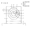
- Figs. 1 and 2 show a cutting apparatus to which a method of controlling an elliptical vibrator is applied according to the present invention.
- Fig. 3 shows a main part of the apparatus shown in Figs. 1 and 2.
- Figs. 4A and 4B illustrate vibratory characteristics of a cutting tool and a control method of automatic track of resonance frequency.
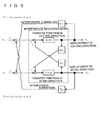
- Fig. 5 illustrates a method of eliminating interference for the method of controlling the elliptical vibrator according to the present invention.
- the elliptical vibratory cutting apparatus shown in Figs. 1 and 2 includes a cutting tool 2 such as bit for cutting a workpiece 1, steel product for example, an elliptical vibrator 3 for causing elliptical vibrations to cutting tool 2, two supporting members 4 for supporting elliptical vibrator 3 with a predetermined space therebetween, and a base 5 on which supporting members 4 are placed.
- a cutting tool 2 such as bit for cutting a workpiece 1
- steel product for example
- an elliptical vibrator 3 for causing elliptical vibrations to cutting tool 2
- two supporting members 4 for supporting elliptical vibrator 3 with a predetermined space therebetween
- a base 5 on which supporting members 4 are placed.
- Elliptical vibrator 3 has its central part formed of a body 6 in the shape of an octagonal prism.
- Step horns 7 protrude respectively from both ends of body 6 in the shape of the octagonal prism, for amplifying elliptical vibrations.
- Step horns 7 are each constituted of a larger cylindrical horn 8 and a smaller cylindrical horn 9 provided to larger horn 8.
- One of the step horns 7 of elliptical vibrator 3 has its end (of smaller horn 9) that is provided with a mount 10 to which cutting tool 2 is attached. Step horns 7 (larger horns 8) can be supported respectively by supporting members 4.
- Octagonal prismatic body 6 has its vertical face 11 on which a (driving) piezoelectric element 12 is provided for generating elliptical vibrations, as well as its horizontal face 13 on which a piezoelectric element 14 is also provided for generating elliptical vibrations.
- Vertical face 11 and horizontal face 13 that form respective sides of octagonal prismatic body 6 are orthogonal to each other.
- the vertical and horizontal faces serve respectively as mounts on which the piezoelectric elements are attached.
- piezoelectric elements 12 and 14 are not necessarily placed respectively on vertical face 11 and horizontal face 13, and thus the piezoelectric elements may be provided on respective faces orthogonal to each other so that flexure vibrations are generated in directions orthogonal to each other.
- the flexure vibrations are not necessarily generated in the orthogonal directions and may be in respective directions that form an angle except for 0° and 180°.
- the apparatus as described above further includes a control mechanism 15 for individually driving and controlling piezoelectric elements 12 and 14.
- a sinusoidal voltage having a predetermined frequency, a predetermined amplitude and a predetermined phase (predetermined phase difference) can be applied to each of the piezoelectric elements 12 and 14.
- the sinusoidal voltage with a predetermined phase difference is applied to piezoelectric elements 12 and 14 each for individually driving piezoelectric elements 12 and 14.
- flexure vibrations can be caused to elliptical vibrator 3.
- the flexure vibrations are generated, according to the sinusoidal voltage, on supporting members 4 as their center.
- the flexure vibrations of elliptical vibrator 3 are mechanically resonated and synthesized.
- a trajectory, in a required shape, of elliptical vibrations can be produced on mount 10 on the end of step horn 7.
- elliptical vibrations can be synthesized and transmitted to cutting tool 2 (mount 10), so as to allow the end (cutting edge) of cutting tool 2 to draw trajectory 16 (see Fig. 3) of the elliptical vibrations in a required shape and thus periodically vibrate elliptically (rotate along the elliptical trajectory).
- Trajectory 16 of the elliptical vibrations can be shaped arbitrarily as required by the elliptical vibratory cutting apparatus. Further, the sinusoidal voltage applied to piezoelectric elements 12 and 14 of elliptical vibrator 3 can have a frequency of 20 KHz, an amplitude (voltage) of 200 V and a phase difference of 90°, for example.
- cutting tool 2 (cutting edge thereof) is elliptically vibrated while workpiece 1 is relatively moved in cutting direction A (Y direction in Fig. 2) at a predetermined cutting speed (m/min), so as to bite workpiece 1 in a biting direction indicated by D (X direction in Fig. 2).
- the direction indicated by B which is the same as cutting direction A, is the direction of a main cutting force
- the direction indicated by C is the direction of a feed force
- detectors (sensor) 17 are provided for detecting flexure vibrations in X and Y directions respectively. Detectors 17 detect flexure vibrations (elliptical vibrations) of elliptical vibrator 3 to transmit a detection signal indicating the vibratory state to control mechanism 15.
- the amount of interference as described above, by vibrations in X (Y) direction, with vibrations in Y (X) direction, can be measured by means of detectors 17.
- piezoelectric elements for measurement or optical displacement meters may be employed as detectors 17 as described above.
- step horns 7 flex not only in X direction but also in Y direction. If the piezoelectric elements are employed as detectors 17, the flexure of the step horns deforms both of the detector 17 for detecting flexure vibrations in X direction and the detector 17 for detecting flexure vibrations in Y direction, and accordingly voltages are generated from the detectors. At this time, the voltage of the detector 17 for detecting Y-direction flexure vibrations can be detected in order to detect the amount of interference with vibrations in Y direction.
- the vibratory state (e.g. amplitude, amount of interference) can indirectly be measured by measuring, by means of an amplifying unit 23, the amount of current when vibrations are being generated.
- Control mechanism 15 includes a control unit 21 for implementing three control systems, i.e., constant-amplitude control, constant-phase-difference control and automatic tracking of resonance frequency, in order to control trajectory 16 of elliptical vibrations.
- trajectory 16 of elliptical vibrations can stably be shaped as required.
- the constant-amplitude control refers to control for maintaining, with stability, a required amplitude (preset target amplitude) of the vibrations in X direction (biting direction D) and Y direction (cutting direction A), for example.
- control mechanism 15 the amplitude of the waveform of the vibrations measured by detectors 17 can be set to the target amplitude.
- the constant-phase-difference control refers to control for maintaining, with stability, a required phase difference (preset target phase difference) of the vibrations in X and Y directions, for example.
- phase difference of the vibrations measured by detectors 17 can be set to the target phase difference.
- the cutting operation by the elliptical vibratory cutting apparatus is accomplished through elliptical vibrations, as described above, that are produced by mechanical resonation and synthesis of the flexure vibrations for obtaining trajectory 16 of the elliptical vibrations that is drawn by the cutting edge of cutting tool 2.
- the frequency of an applied voltage is always equal to the resonance frequency.
- the resonance frequency cannot be specified due to a slight difference between respective resonance frequencies of the cutting tool with respect to the two directions.
- Figs. 4A and 4B show measurements of the vibratory characteristics of the cutting tool that are taken by detectors 17 (piezoelectric elements for measurement).
- Fig. 4A shows gain with respect to cutting direction (Y direction) and biting direction (X direction)
- Fig. 4B shows phase delay with respect to the cutting direction (Y direction) and the biting direction (X direction).
- the average phase delay regarding the two directions is set to -90° in order to achieve a sufficient vibratory amplitude for both of the two directions.
- the phase difference between an output waveform from detector 17 and an input waveform from control unit 21 is measured, and the average of respective phase delays with respect to the two directions is maintained at an arbitrary target value (e.g. -90°), by adjusting the frequency of the voltage applied to the driving piezoelectric elements.
- the average phase delay may be a weighed average. In this case, an arbitrary manner of weighting can be applied.
- the control is exercised for keeping the average phase delay of the two directions, i.e., X and Y directions, at approximately -90°.
- This control is referred to as the automatic tracking of resonance frequency.
- Control mechanism 15 further includes an interference eliminating unit 22 for correctively eliminating an amount of interference with flexure vibrations in the X and Y directions. Then, the amount of interference with the flexure vibrations in X and Y directions can correctively be removed by interference eliminating unit 22.
- the amount of interference by flexure vibrations in X direction, with flexure vibrations in Y direction, is eliminated by controlling the voltage applied to Y-direction-drive piezoelectric element 14 for canceling the amount of interference.
- the amount of interference can thus be removed correctively.
- detection signals from detectors 17 can be input.
- Fig. 5 illustrates a mechanism of interference (tool interference) with vibrations in X and Y directions as well as an interference eliminating system (interference eliminating unit 22) of the apparatus shown in Figs. 1-3.
- the piezoelectric action causes a vibrating force represented by F 1 ⁇ cos ( ⁇ t + ⁇ 1 ) to piezoelectric element 12, and this vibrating force causes, to elliptical vibrator 3, a displacement in X direction, ⁇ 1 ⁇ cos ( ⁇ t + ⁇ 1 - ⁇ ).
- this displacement causes a vibrating force (tool interference), represented by K 21 ⁇ ⁇ 1 ⁇ cos ( ⁇ t + ⁇ 1 - ⁇ ), in Y direction orthogonal to X direction.
- That displacement in other words, the displacement in X direction causing the vibrating force in Y direction has a waveform which can be detected by detector 17.
- a vibrating voltage of P 21 ⁇ 1 ⁇ cos ( ⁇ t + ⁇ 1 - ⁇ ) is applied to Y-direction-drive piezoelectric element 14. Then, this vibrating voltage causes a vibrating force of P 21 ⁇ F 2 /E 2 ⁇ ⁇ 1 ⁇ cos ( ⁇ t + ⁇ 1 - ⁇ ) in Y direction.
- the amount of interference specific to this system that is included in the displacement which is caused by the vibrating force in X direction is entered, as a disturbance component, to the vibrating force in Y direction and is accordingly taken in transfer function G 2 (S), in consideration of the interference removal.
- Tool interference which is caused when vibrating voltage V 2 represented by E 2 - cos ( ⁇ t + ⁇ 2 ) is applied to only the piezoelectric element 14 for Y-direction-drive can also be eliminated correctively by canceling the interference as done with respect to X direction as described above.
- the elliptical vibratory cutting apparatus (interference eliminating unit 22 of control mechanism 15) can efficiently and correctively remove the tool interference with respect to both of the two directions, X and Y directions, and thus cut, with stability, workpiece 1 by means of cutting tool 2 through elliptical vibrations thereof.
- a sinusoidal voltage having a predetermined phase difference is applied from control mechanism 15 to piezoelectric elements 12 and 14 each for driving them.
- flexure vibrations of elliptical vibrator 3 are generated in X and Y directions respectively according to piezoelectric elements 12 and 14.
- the flexure vibrations are synthesized to cause elliptical vibrations of cutting tool 2 on mount 10 of elliptical vibrator 3.
- workpiece 1 can be cut by means of cutting tool 2 through elliptical vibrations thereof.
- the workpiece is cut by means of the cutting tool through elliptical vibrations.
- the trajectory of the elliptical vibrations that is drawn by the edge of the cutting tool can be controlled with stability so that the trajectory has a required shape. Consequently, the workpiece can be processed with high precision by the elliptical vibratory cutting operation.
- Amplifying unit (amplifier) 23 of control mechanism 15 described above amplifies the voltage from interference eliminating unit 22 for supplying the amplified voltage to piezoelectric elements 12 and 14.
- the elliptical vibratory cutting apparatus is herein described above as an elliptical vibratory processing apparatus.
- the present invention is applicable to any processing apparatus for grinding, abrading, cutting and welding for example.
- any tools used for these processing operations may elliptically be vibrated.
- a blade for the cutting operation and a buff or abrasive pad for the abrading operation may elliptically be vibrated.
- a workpiece to be processed may elliptically be vibrated.
- the present invention is effective as a method for controlling a resonance ultrasonic motor.
- the flexural vibrations are used for controlling the elliptical vibrator.
- two actuator systems such as piezoelectric elements may be used for allowing each piezoelectric element to directly cause displacement of the elliptical vibrator.
- piezoelectric elements each having a constant phase difference displace and accordingly vibrate the elliptical vibrator in respective directions that are orthogonal to each other, so that so-called longitudinal vibrations are generated.
- so-called torsional vibrations may be generated from torsional deformation caused by actuators.
- any vibration mode such as shear vibrations and radial vibrations may be used.
- any deformation may be caused for producing displacement from which such vibrations are generated.
- the present invention is applicable to any combination of these vibration modes.
- the amount of interference, by vibrations in one direction, with vibrations in another direction, is correctively eliminated from the vibrations in that another direction.
- one direction and another direction in which vibrations are generated are not necessarily orthogonal to each other, and the angle formed by these directions may be any angle except for 0° and 180°.
- a workpiece is processed by means of a tool through elliptical vibrations, and the trajectory of the elliptical vibrations that is drawn by an edge of the tool can be controlled with stability so that the trajectory has a required shape.
- the present invention is highly effective in that the workpiece can be processed with high precision through the elliptical vibrations.
Landscapes
- Engineering & Computer Science (AREA)
- Mechanical Engineering (AREA)
- Turning (AREA)
- Apparatuses For Generation Of Mechanical Vibrations (AREA)
Applications Claiming Priority (2)
| Application Number | Priority Date | Filing Date | Title |
|---|---|---|---|
| JP2001048885A JP3806603B2 (ja) | 2001-02-23 | 2001-02-23 | 楕円振動装置及び楕円振動装置の制御方法 |
| JP2001048885 | 2001-02-23 |
Publications (3)
| Publication Number | Publication Date |
|---|---|
| EP1234627A2 true EP1234627A2 (fr) | 2002-08-28 |
| EP1234627A3 EP1234627A3 (fr) | 2002-09-18 |
| EP1234627B1 EP1234627B1 (fr) | 2005-04-20 |
Family
ID=18910074
Family Applications (1)
| Application Number | Title | Priority Date | Filing Date |
|---|---|---|---|
| EP02251220A Expired - Lifetime EP1234627B1 (fr) | 2001-02-23 | 2002-02-22 | Procédé de commande d'un vibrateur elliptique |
Country Status (4)
| Country | Link |
|---|---|
| US (1) | US6776563B2 (fr) |
| EP (1) | EP1234627B1 (fr) |
| JP (1) | JP3806603B2 (fr) |
| DE (1) | DE60203753T2 (fr) |
Cited By (6)
| Publication number | Priority date | Publication date | Assignee | Title |
|---|---|---|---|---|
| EP1523049A3 (fr) * | 2003-10-11 | 2006-04-05 | Johnson Electric S.A. | Moteur électrique |
| WO2008118479A1 (fr) * | 2007-03-27 | 2008-10-02 | Panasonic Corporation | Systèmes d'usinage assisté par vibrations avec des actionneurs superposés |
| EP2103376A1 (fr) * | 2008-03-19 | 2009-09-23 | Panasonic Corporation | Dispositif de découpe, procédé d'usinage et matrice usinée par le procédé d'usinage |
| EP1948392A4 (fr) * | 2005-11-15 | 2010-11-17 | 3M Innovative Properties Co | Outil de coupe a deplacement variable et independant dans une direction x et une direction z au sein et lateralement le long d une piece a usiner pour former des microstructures |
| CN103611988A (zh) * | 2013-11-17 | 2014-03-05 | 长春工业大学 | 一种非共振三维椭圆金刚石振动切削柔性装置 |
| CN104959678A (zh) * | 2015-06-24 | 2015-10-07 | 中国北方车辆研究所 | 一种球支承油线加工装置 |
Families Citing this family (21)
| Publication number | Priority date | Publication date | Assignee | Title |
|---|---|---|---|---|
| SE514525E (sv) * | 1998-10-22 | 2010-02-16 | Staffansboda Cie Ab | Anordning och metod för styrning av vibrationer samt verktygshållare |
| SE517878C2 (sv) * | 2000-12-08 | 2002-07-30 | Sandvik Ab | Förfarande och anordning för vibrationsdämpning av metalliska verktyg för spånavskiljande bearbetning samt verktyg innefattande en dylik anordning |
| GB2435189B (en) * | 2004-12-17 | 2010-06-23 | Milwaukee Electric Tool Corp | Saw and Blade with Operational Communication |
| US7198043B1 (en) | 2005-08-26 | 2007-04-03 | Gang Zhang | Method for extending diamond tool life in diamond machining of materials that chemically react with diamond |
| US7508116B2 (en) * | 2005-09-07 | 2009-03-24 | Panasonic Corporation | Method and apparatus for vibration machining with two independent axes |
| DE102006041208B4 (de) * | 2006-09-02 | 2014-08-07 | Leica Biosystems Nussloch Gmbh | Messgerät für ein Vibrationsmikrotom und Vibrationsmikrotom mit einem Messgerät |
| JP5103620B2 (ja) * | 2007-03-14 | 2012-12-19 | 国立大学法人名古屋大学 | 楕円振動切削装置および楕円振動切削方法 |
| KR101011092B1 (ko) * | 2007-07-19 | 2011-01-25 | 도시바 기카이 가부시키가이샤 | 미세 형상 절삭 가공 장치 및 미세 형상 절삭 가공 방법 |
| JP2009096687A (ja) * | 2007-10-18 | 2009-05-07 | Nakamura Tome Precision Ind Co Ltd | 硬質脆性板のスクライブ方法及び装置 |
| US8205530B2 (en) * | 2008-10-03 | 2012-06-26 | Subramanian Sundaresa V | Processes for improving tool life and surface finish in high speed machining |
| CN101972856B (zh) * | 2010-09-16 | 2012-02-08 | 长春工业大学 | 一种非共振三维椭圆金刚石飞切光学自由曲面方法及专用装置 |
| WO2014033905A1 (fr) * | 2012-08-31 | 2014-03-06 | Minami Hironori | Procédé et dispositif de traitement d'un verre trempé |
| CN106141761B (zh) * | 2016-07-26 | 2018-02-16 | 南京航空航天大学 | 并联结构的三维超声椭圆振动切削装置及轨迹产生方法 |
| JP2018079540A (ja) * | 2016-11-16 | 2018-05-24 | 国立大学法人名古屋大学 | 加工装置及び加工方法 |
| CN107350558B (zh) * | 2017-03-02 | 2019-07-09 | 南京航空航天大学 | 伞状并联结构三维超声椭圆振动切削装置及轨迹产生方法 |
| JP7311098B2 (ja) * | 2017-05-09 | 2023-07-19 | 国立大学法人東海国立大学機構 | 振動切削装置、振動装置および切削方法 |
| ES2894144T3 (es) * | 2019-03-15 | 2022-02-11 | Siemens Ag | Máquina herramienta con orientación optimizada de amortiguadores de vibración |
| CN112872402A (zh) * | 2021-03-29 | 2021-06-01 | 福州大学 | 超声振动复合钻削装置及其工作方法 |
| JP2023089486A (ja) * | 2021-12-16 | 2023-06-28 | セイコーエプソン株式会社 | 圧電モーターの制御方法、圧電モーターおよびロボット |
| CN114393253B (zh) * | 2022-02-09 | 2022-08-23 | 哈尔滨工业大学(深圳) | 一种多部件协同振动的跨尺度结构特征表面加工方法 |
| WO2024159826A1 (fr) * | 2023-01-31 | 2024-08-08 | Tsinghua University | Procédé d'usinage par vibration-ciselage |
Family Cites Families (31)
| Publication number | Priority date | Publication date | Assignee | Title |
|---|---|---|---|---|
| US2736144A (en) | 1956-02-28 | thatcher | ||
| US3559259A (en) | 1967-12-30 | 1971-02-02 | Rikagaku Kenkyusho | Method for connecting a longitudinal vibrator with a bending vibrator in an ultrasonic vibrating cutting system, a tool and a tool holder thereof |
| FR2178367A5 (fr) | 1972-03-29 | 1973-11-09 | Guillermier Bernard | |
| JPS5766822A (en) | 1980-10-08 | 1982-04-23 | Inoue Japax Res Inc | Discharge processing method |
| SU986605A1 (ru) | 1981-07-27 | 1983-01-07 | Ордена Трудового Красного Знамени Институт Сверхтвердых Материалов Ан Усср | Устройство дл обработки фасонных поверхностей |
| US4651599A (en) | 1983-08-01 | 1987-03-24 | Hans Ley | Method for producing workpieces having polygonal outer and/or inner contours |
| US4742260A (en) | 1986-02-06 | 1988-05-03 | Hiroshi Shimizu | Piezoelectrically driving device |
| EP0277823B1 (fr) | 1987-02-04 | 1991-04-24 | Taga Electric Co. Ltd. | Dispositif de coupe à ultrasons |
| JPS63283802A (ja) | 1987-05-13 | 1988-11-21 | Taga Electric Co Ltd | 超音波振動切削装置 |
| JPS6477484A (en) | 1987-09-18 | 1989-03-23 | Nec Corp | Ultrasonic motor and method for driving same |
| JPH0744856B2 (ja) | 1988-12-16 | 1995-05-15 | 株式会社トーキン | 超音波モータ |
| JPH0373201A (ja) | 1989-08-10 | 1991-03-28 | Nippondenso Co Ltd | 振動加工装置 |
| JPH0386087A (ja) | 1989-08-29 | 1991-04-11 | Brother Ind Ltd | アクチュエータ |
| JP2686000B2 (ja) | 1991-07-17 | 1997-12-08 | 株式会社東芝 | 振動切削方法及び切削装置 |
| US5448128A (en) | 1991-12-12 | 1995-09-05 | Honda Denshi Kabushiki Kaisha | Vibration type driving device |
| JP3245245B2 (ja) | 1993-02-05 | 2002-01-07 | 沖電気工業株式会社 | 超音波モータ及び超音波搬送装置 |
| KR0151745B1 (ko) | 1993-02-08 | 1999-04-15 | 모리시타 요이찌 | 초음파모터 및 초음파모터의 제어방법 |
| JP3500434B2 (ja) * | 1993-09-01 | 2004-02-23 | 財団法人新産業創造研究機構 | 振動切削加工方法および振動切削加工装置 |
| JPH0937574A (ja) | 1995-05-12 | 1997-02-07 | Nikon Corp | 振動アクチュエータ及びその制御方法 |
| US6404104B1 (en) | 1997-11-27 | 2002-06-11 | Canon Kabushiki Kaisha | Vibration type actuator and vibration type driving apparatus |
| JP2000060163A (ja) * | 1998-02-10 | 2000-02-25 | Nikon Corp | 振動アクチュエ―タ |
| US5913955A (en) * | 1998-02-12 | 1999-06-22 | Sandia Corporation | Vibration damping method and apparatus |
| JP4268246B2 (ja) * | 1998-08-12 | 2009-05-27 | Towa株式会社 | 楕円振動切削装置 |
| US6637303B2 (en) * | 1998-08-12 | 2003-10-28 | Toshimichi Moriwaki | Elliptical vibration cutting method and elliptical vibration cutting apparatus |
| SE519487C2 (sv) * | 1998-10-22 | 2003-03-04 | Rolf Zimmergren | Metod och anordning för vibrationsstyrning vid borrande svarvning samt verktygshållare för borrande svarvning |
| SE515157C2 (sv) | 1998-10-22 | 2001-06-18 | Ingvar Claesson | Metod och anordning för styrning av svarvoperation |
| AT411792B (de) | 1999-01-11 | 2004-05-25 | Vaillant Gmbh | Heizeinrichtung |
| JP2000218401A (ja) | 1999-02-01 | 2000-08-08 | Fuji Kogyo Kk | 超音波振動切削装置 |
| JP2001113401A (ja) * | 1999-10-19 | 2001-04-24 | Towa Corp | 楕円振動切削装置及び楕円振動切削方法 |
| JP2002112563A (ja) * | 2000-09-29 | 2002-04-12 | Minolta Co Ltd | アクチュエータの駆動方法および装置 |
| SE517878C2 (sv) * | 2000-12-08 | 2002-07-30 | Sandvik Ab | Förfarande och anordning för vibrationsdämpning av metalliska verktyg för spånavskiljande bearbetning samt verktyg innefattande en dylik anordning |
-
2001
- 2001-02-23 JP JP2001048885A patent/JP3806603B2/ja not_active Expired - Lifetime
-
2002
- 2002-02-21 US US10/081,067 patent/US6776563B2/en not_active Expired - Fee Related
- 2002-02-22 EP EP02251220A patent/EP1234627B1/fr not_active Expired - Lifetime
- 2002-02-22 DE DE60203753T patent/DE60203753T2/de not_active Expired - Lifetime
Cited By (11)
| Publication number | Priority date | Publication date | Assignee | Title |
|---|---|---|---|---|
| EP1523049A3 (fr) * | 2003-10-11 | 2006-04-05 | Johnson Electric S.A. | Moteur électrique |
| US7274131B2 (en) | 2003-10-11 | 2007-09-25 | Johnson Electric S.A. | Piezoelectric motor with actuator to move the rotor about two orthogonal axes |
| EP1948392A4 (fr) * | 2005-11-15 | 2010-11-17 | 3M Innovative Properties Co | Outil de coupe a deplacement variable et independant dans une direction x et une direction z au sein et lateralement le long d une piece a usiner pour former des microstructures |
| WO2008118479A1 (fr) * | 2007-03-27 | 2008-10-02 | Panasonic Corporation | Systèmes d'usinage assisté par vibrations avec des actionneurs superposés |
| WO2008118158A1 (fr) * | 2007-03-27 | 2008-10-02 | Panasonic Corporation | Système d'usinage assisté par vibrations à actionneurs empilés |
| US7687975B2 (en) | 2007-03-27 | 2010-03-30 | Panasonic Corporation | Vibration assisted machining system with stacked actuators |
| CN101641182B (zh) * | 2007-03-27 | 2013-06-05 | 松下电器产业株式会社 | 振动辅助机械加工(vam)系统 |
| EP2103376A1 (fr) * | 2008-03-19 | 2009-09-23 | Panasonic Corporation | Dispositif de découpe, procédé d'usinage et matrice usinée par le procédé d'usinage |
| US8381555B2 (en) | 2008-03-19 | 2013-02-26 | Panasonic Corporation | Cutting device, machining method, and die machined by the machining method |
| CN103611988A (zh) * | 2013-11-17 | 2014-03-05 | 长春工业大学 | 一种非共振三维椭圆金刚石振动切削柔性装置 |
| CN104959678A (zh) * | 2015-06-24 | 2015-10-07 | 中国北方车辆研究所 | 一种球支承油线加工装置 |
Also Published As
| Publication number | Publication date |
|---|---|
| EP1234627B1 (fr) | 2005-04-20 |
| US6776563B2 (en) | 2004-08-17 |
| JP2002254201A (ja) | 2002-09-10 |
| JP3806603B2 (ja) | 2006-08-09 |
| US20020119021A1 (en) | 2002-08-29 |
| DE60203753T2 (de) | 2005-10-06 |
| DE60203753D1 (de) | 2005-05-25 |
| EP1234627A3 (fr) | 2002-09-18 |
Similar Documents
| Publication | Publication Date | Title |
|---|---|---|
| EP1234627B1 (fr) | Procédé de commande d'un vibrateur elliptique | |
| JP5103620B2 (ja) | 楕円振動切削装置および楕円振動切削方法 | |
| EP0823680B1 (fr) | Méthode et dispositif pour contrôler des vibrations piézoélectriques | |
| US8723472B2 (en) | Servo control device | |
| CN110385798B (zh) | 加工装置 | |
| JP4268246B2 (ja) | 楕円振動切削装置 | |
| Wu et al. | A new centerless grinding technique using a surface grinder | |
| US6637303B2 (en) | Elliptical vibration cutting method and elliptical vibration cutting apparatus | |
| JP3656544B2 (ja) | 複合振動子及びそれを用いた振動ジャイロ、及び複合振動子の製造方法 | |
| JP2008212916A (ja) | 超音波複合振動装置 | |
| KR101862729B1 (ko) | 초음파 가진을 이용한 공구의 진동특성 분석장치 | |
| JP6882685B2 (ja) | 振動系の制御装置およびワーク搬送装置 | |
| US6621241B2 (en) | System and method for reducing oscillating tool-induced reaction forces | |
| JP2001099639A (ja) | 表面形状測定方法 | |
| JPH08170636A (ja) | リニアガイドユニット | |
| JP4585346B2 (ja) | 超音波モータの制御方法 | |
| JPS59124546A (ja) | 要位置決め物の位置決め装置 | |
| JPS63232901A (ja) | 超音波振動切削装置 | |
| JP2021122770A (ja) | 自励発振装置、切削装置、自励発振装置の制御方法及び切削方法 | |
| CN114406773B (zh) | 一种两自由度刀具伺服装置 | |
| JP2817854B2 (ja) | 圧接ローラのニップ幅の測定方法及び装置 | |
| JPH04156982A (ja) | 超音波振動子の周波数追尾制御方法 | |
| TW201943625A (zh) | 振動系統之控制裝置及工件搬送裝置 | |
| JPH09311041A (ja) | 角速度検出装置 | |
| JPH01174281A (ja) | 振動波モータ |
Legal Events
| Date | Code | Title | Description |
|---|---|---|---|
| PUAI | Public reference made under article 153(3) epc to a published international application that has entered the european phase |
Free format text: ORIGINAL CODE: 0009012 |
|
| PUAL | Search report despatched |
Free format text: ORIGINAL CODE: 0009013 |
|
| AK | Designated contracting states |
Kind code of ref document: A2 Designated state(s): AT BE CH CY DE DK ES FI FR GB GR IE IT LI LU MC NL PT SE TR |
|
| AX | Request for extension of the european patent |
Free format text: AL;LT;LV;MK;RO;SI |
|
| AK | Designated contracting states |
Kind code of ref document: A3 Designated state(s): AT BE CH CY DE DK ES FI FR GB GR IE IT LI LU MC NL PT SE TR |
|
| AX | Request for extension of the european patent |
Free format text: AL;LT;LV;MK;RO;SI |
|
| 17P | Request for examination filed |
Effective date: 20021012 |
|
| AKX | Designation fees paid |
Designated state(s): DE GB NL |
|
| 17Q | First examination report despatched |
Effective date: 20030912 |
|
| GRAP | Despatch of communication of intention to grant a patent |
Free format text: ORIGINAL CODE: EPIDOSNIGR1 |
|
| GRAS | Grant fee paid |
Free format text: ORIGINAL CODE: EPIDOSNIGR3 |
|
| GRAA | (expected) grant |
Free format text: ORIGINAL CODE: 0009210 |
|
| AK | Designated contracting states |
Kind code of ref document: B1 Designated state(s): DE GB NL |
|
| REG | Reference to a national code |
Ref country code: GB Ref legal event code: FG4D |
|
| REG | Reference to a national code |
Ref country code: IE Ref legal event code: FG4D |
|
| REF | Corresponds to: |
Ref document number: 60203753 Country of ref document: DE Date of ref document: 20050525 Kind code of ref document: P |
|
| PLBE | No opposition filed within time limit |
Free format text: ORIGINAL CODE: 0009261 |
|
| STAA | Information on the status of an ep patent application or granted ep patent |
Free format text: STATUS: NO OPPOSITION FILED WITHIN TIME LIMIT |
|
| 26N | No opposition filed |
Effective date: 20060123 |
|
| PGFP | Annual fee paid to national office [announced via postgrant information from national office to epo] |
Ref country code: GB Payment date: 20091222 Year of fee payment: 9 |
|
| PGFP | Annual fee paid to national office [announced via postgrant information from national office to epo] |
Ref country code: DE Payment date: 20100219 Year of fee payment: 9 |
|
| PGFP | Annual fee paid to national office [announced via postgrant information from national office to epo] |
Ref country code: NL Payment date: 20100215 Year of fee payment: 9 |
|
| REG | Reference to a national code |
Ref country code: NL Ref legal event code: V1 Effective date: 20110901 |
|
| GBPC | Gb: european patent ceased through non-payment of renewal fee |
Effective date: 20110222 |
|
| PG25 | Lapsed in a contracting state [announced via postgrant information from national office to epo] |
Ref country code: NL Free format text: LAPSE BECAUSE OF NON-PAYMENT OF DUE FEES Effective date: 20110901 |
|
| REG | Reference to a national code |
Ref country code: DE Ref legal event code: R119 Ref document number: 60203753 Country of ref document: DE Effective date: 20110901 |
|
| PG25 | Lapsed in a contracting state [announced via postgrant information from national office to epo] |
Ref country code: GB Free format text: LAPSE BECAUSE OF NON-PAYMENT OF DUE FEES Effective date: 20110222 |
|
| PG25 | Lapsed in a contracting state [announced via postgrant information from national office to epo] |
Ref country code: DE Free format text: LAPSE BECAUSE OF NON-PAYMENT OF DUE FEES Effective date: 20110901 |