EP1234760A2 - Blocage automatique de suspension pour bicyclettes - Google Patents
Blocage automatique de suspension pour bicyclettes Download PDFInfo
- Publication number
- EP1234760A2 EP1234760A2 EP02004275A EP02004275A EP1234760A2 EP 1234760 A2 EP1234760 A2 EP 1234760A2 EP 02004275 A EP02004275 A EP 02004275A EP 02004275 A EP02004275 A EP 02004275A EP 1234760 A2 EP1234760 A2 EP 1234760A2
- Authority
- EP
- European Patent Office
- Prior art keywords
- bicycles
- bottom bracket
- assembly
- shock absorber
- automatic suspension
- Prior art date
- Legal status (The legal status is an assumption and is not a legal conclusion. Google has not performed a legal analysis and makes no representation as to the accuracy of the status listed.)
- Withdrawn
Links
- 239000000725 suspension Substances 0.000 title claims abstract description 89
- 239000006096 absorbing agent Substances 0.000 claims abstract description 50
- 230000035939 shock Effects 0.000 claims abstract description 50
- 239000013536 elastomeric material Substances 0.000 claims description 23
- 230000036316 preload Effects 0.000 claims description 15
- 238000006073 displacement reaction Methods 0.000 claims description 11
- 230000010355 oscillation Effects 0.000 claims description 2
- 229920002725 thermoplastic elastomer Polymers 0.000 claims description 2
- 229920001971 elastomer Polymers 0.000 claims 1
- 238000013016 damping Methods 0.000 description 4
- 239000012530 fluid Substances 0.000 description 4
- 230000001133 acceleration Effects 0.000 description 2
- 230000000903 blocking effect Effects 0.000 description 2
- 229920003051 synthetic elastomer Polymers 0.000 description 2
- 239000005061 synthetic rubber Substances 0.000 description 2
- 230000004913 activation Effects 0.000 description 1
- 230000009194 climbing Effects 0.000 description 1
- 230000006835 compression Effects 0.000 description 1
- 238000007906 compression Methods 0.000 description 1
- 230000000694 effects Effects 0.000 description 1
- 239000000463 material Substances 0.000 description 1
- 238000004137 mechanical activation Methods 0.000 description 1
- 230000003534 oscillatory effect Effects 0.000 description 1
- 230000021715 photosynthesis, light harvesting Effects 0.000 description 1
Images


Classifications
-
- B—PERFORMING OPERATIONS; TRANSPORTING
- B62—LAND VEHICLES FOR TRAVELLING OTHERWISE THAN ON RAILS
- B62K—CYCLES; CYCLE FRAMES; CYCLE STEERING DEVICES; RIDER-OPERATED TERMINAL CONTROLS SPECIALLY ADAPTED FOR CYCLES; CYCLE AXLE SUSPENSIONS; CYCLE SIDE-CARS, FORECARS, OR THE LIKE
- B62K25/00—Axle suspensions
- B62K25/04—Axle suspensions for mounting axles resiliently on cycle frame or fork
- B62K25/28—Axle suspensions for mounting axles resiliently on cycle frame or fork with pivoted chain-stay
- B62K25/286—Axle suspensions for mounting axles resiliently on cycle frame or fork with pivoted chain-stay the shock absorber being connected to the chain-stay via a linkage mechanism
-
- B—PERFORMING OPERATIONS; TRANSPORTING
- B62—LAND VEHICLES FOR TRAVELLING OTHERWISE THAN ON RAILS
- B62K—CYCLES; CYCLE FRAMES; CYCLE STEERING DEVICES; RIDER-OPERATED TERMINAL CONTROLS SPECIALLY ADAPTED FOR CYCLES; CYCLE AXLE SUSPENSIONS; CYCLE SIDE-CARS, FORECARS, OR THE LIKE
- B62K25/00—Axle suspensions
- B62K25/04—Axle suspensions for mounting axles resiliently on cycle frame or fork
- B62K2025/044—Suspensions with automatic adjustment
-
- B—PERFORMING OPERATIONS; TRANSPORTING
- B62—LAND VEHICLES FOR TRAVELLING OTHERWISE THAN ON RAILS
- B62K—CYCLES; CYCLE FRAMES; CYCLE STEERING DEVICES; RIDER-OPERATED TERMINAL CONTROLS SPECIALLY ADAPTED FOR CYCLES; CYCLE AXLE SUSPENSIONS; CYCLE SIDE-CARS, FORECARS, OR THE LIKE
- B62K25/00—Axle suspensions
- B62K25/04—Axle suspensions for mounting axles resiliently on cycle frame or fork
- B62K2025/047—Axle suspensions for mounting axles resiliently on cycle frame or fork with suspension locking means
Definitions
- This invention applies to bicycles, more particularly to bicycles that utilize wheel suspension similar to that of a car or motorcycle, and the automatic lockout of the suspension when required to optimize the bicycle's operation.
- a widely adopted solution to this problem is the introduction of a suspension lockout that the rider can operate when desired.
- the term lockout refers to one or more of the following elements in combination: mechanically limiting the amount of suspension travel; increasing the damping response of the shock absorber - most importantly in compression; increasing the force-displacement rate of the suspension; increasing the spring preload of the suspension.
- the rider would engage the lockout during heavy pedaling as required by hill climbing or acceleration but could disengage it for coasting and downhill operation over bumpy terrain.
- the most common form of bicycle suspension lockout consists of a valve that limits the flow of oil past the shock absorber's main piston. Normally the shock absorber passes fluid between two chambers past a main piston that is moving in response to the suspension motion.
- This fluid is variably throttled to achieve the correct damping response. By reducing or blocking the throttle area, a significant increase in damping response is created that significantly slows the suspension movement.
- the majority of these systems utilize direct acting mechanical activation via a cable routed from a convenient location for the rider to the front or rear shock absorbers, or to both. Some systems utilize electrical activation.
- U.S. Patent No. 5,354,085 to Gally describes a suspension system where the locking device is automatically actuated by way of a drive force sensor, which permits automatic lockout as increased force is exerted on the pedals.
- This device does not have the ability to sense the inclination angle of the bicycle.
- a crank assembly means a pedal, crankarm, crankshaft, chainwheel and bearing assembly.
- an automatic suspension lockout assembly for bicycles comprises a crank assembly compliantly mounted to a frame such that a combination of pedaling forces and uphill bicycle inclination creates a small motion suitable for controlling a hydraulic valve in a shock absorber of the bicycle suspension assembly resulting in lockout of the suspension.
- an automatic suspension lockout assembly for bicycles comprises a crank assembly mounted in a bottom bracket adapted to be rotatably attached to a frame via a mounting pivot; a chain adapted for power transfer linking the chainwheel to a rear wheel assembly; and a resilient member adapted to create a predetermined stiffness between the bottom bracket and the frame so that rotational motion of the bottom bracket is limited; such that the relative movement between the bottom bracket and the frame caused by a tension force in the chain during pedaling is transferred via a linkage to a hydraulic valve in the suspension shock absorber.
- the automatic suspension lockout assembly for bicycles comprises a crank assembly eccentrically mounted internally in a bottom bracket rigidly attached to the frame; a chain adapted for power transfer linking the chainwheel to a rear wheel assembly; an elastomeric material adapted to attach the crank assembly to the bottom bracket so that eccentric rotational motion of said assembly is limited; such that movement of the crank assembly relative to the bottom bracket and frame caused by a tension force in the chain during pedaling is transferred via a linkage to a hydraulic valve in a suspension shock absorber to lock out suspension movement.
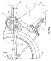
- the pedals (1) of a bicycle are attached to a front chainwheel (2) via a crankshaft and bearings (3) which is mounted to the mainframe (4) via a bottom bracket (5).
- the crankshaft is normally constrained from movement in the bottom bracket in all degrees of freedom except the desired rotation for pedaling energy transfer to the rear wheel assembly (6) via the chain (8).
- the bottom bracket (5) is rotatably attached to the mainframe via a mounting pivot (7).
- the mounting pivot is located directly above the crankshaft so that the tension force (Fc) in the chain (8) caused by the pedaling force (Fp) creates rotational motion (Rm) of the bottom bracket (5) around the mounting pivot (7), as best illustrated in Figure 4A.
- a control spring (9) is mounted between the bottom bracket and mainframe so that the tension in the chain creates proportional rotational motion of the bottom bracket around the mounting pivot.
- the force/displacement rate of the control spring is chosen to accommodate the maximum desired pedaling force threshold within the rotational travel limits of the bottom bracket which is to be less than twenty-five degrees for normal pedaling force (Fp) inputs. This motion is indiscernible to the rider during pedaling.
- a connector rod (10) transmits the bottom bracket motion to the suspension's shock absorber (11).
- An internal linkage (12) in the shock absorber operates a valve (13) that inhibits fluid flow. Limiting the flow creates a hydraulic lock that slows or stops all suspension motion, referred to as lockout whether the flow is slowed or stopped.
- control damper (14) in parallel with the control spring (9) is desirable as it increases the dynamic time constant of the pivoting bottom bracket (5) so that the valve (13) motion is not overly rapid or oscillatory.
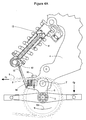
- crankshaft and bearings (3) are mounted eccentrically inside the bottom bracket (5).
- the bottom bracket is mounted solidly to the mainframe as in a conventional bicycle.
- An elastomeric material (15) such as synthetic rubber is utilized to attach the crankshaft and bearings (3) to the bottom bracket (5).
- the elastomeric material allows the crankshaft and bearings to eccentrically rotate in the bottom bracket in response to tension force (Fc) in the chain (8) caused by the pedaling force (Fp).
- the force/displacement rate of the elastomeric material is chosen to limit the eccentric motion of the crankshaft and bearings (3) to less than twenty-five degrees for normal pedaling force (Fp) inputs.
- the elastomeric material can be chosen and designed to provide the correct level of damping required by the system as the characteristic is inherent to this type of material.
- a connector rod (10) transmits the eccentric motion of the crankshaft and bearings (3) to the suspension's shock absorber (11).
- An internal linkage (12) in the shock absorber (11) operates a valve (13) that significantly inhibits fluid flow. This blocking of the flow creates a hydraulic lock that limits or stops all suspension motion.
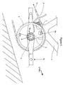
- crankshaft and bearings are mounted inside a bottom bracket (5) which is slideably attached to the mainframe (4) via a linear bearing (20) that moves parallel to the tight span of the chain in response to the tension force (Fc) in the chain.
- a control spring (9) is mounted between the bottom bracket (5) and the mainframe (4). The force displacement rate of the control spring is chosen to accommodate the largest possible pedaling force threshold within the travel range of the linear bearing which is small enough to be indiscernible to the rider.
- a connector rod (10) or cable (17) transmits the linear motion of the crankshaft and bearings (3) to the suspension's shock absorber (11).
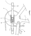
- a pre-load setting mechanism (16) capable of adjusting the pre-load of the control spring (9) or elastomeric material (15) is desirable to adjust the threshold at which the pedaling force (Fp) cause the valve (13) to hydraulically lock the suspension, as illustrated in Figures 4A and 4B.
- actuation of the valve (13) can be achieved at any desired pedaling force threshold.
Landscapes
- Engineering & Computer Science (AREA)
- Mechanical Engineering (AREA)
- Axle Suspensions And Sidecars For Cycles (AREA)
- Shafts, Cranks, Connecting Bars, And Related Bearings (AREA)
- Vibration Prevention Devices (AREA)
- Fluid-Damping Devices (AREA)
- Motorcycle And Bicycle Frame (AREA)
- Steering Devices For Bicycles And Motorcycles (AREA)
Applications Claiming Priority (2)
| Application Number | Priority Date | Filing Date | Title |
|---|---|---|---|
| US27141101P | 2001-02-27 | 2001-02-27 | |
| US271411P | 2001-02-27 |
Publications (2)
| Publication Number | Publication Date |
|---|---|
| EP1234760A2 true EP1234760A2 (fr) | 2002-08-28 |
| EP1234760A3 EP1234760A3 (fr) | 2003-09-17 |
Family
ID=23035426
Family Applications (1)
| Application Number | Title | Priority Date | Filing Date |
|---|---|---|---|
| EP02004275A Withdrawn EP1234760A3 (fr) | 2001-02-27 | 2002-02-27 | Blocage automatique de suspension pour bicyclettes |
Country Status (9)
| Country | Link |
|---|---|
| US (1) | US20020117830A1 (fr) |
| EP (1) | EP1234760A3 (fr) |
| JP (1) | JP2002308176A (fr) |
| KR (1) | KR20020070155A (fr) |
| CN (1) | CN1392081A (fr) |
| BR (1) | BR0201674A (fr) |
| CA (1) | CA2373785A1 (fr) |
| MX (1) | MXPA02002156A (fr) |
| TW (1) | TW521054B (fr) |
Cited By (9)
| Publication number | Priority date | Publication date | Assignee | Title |
|---|---|---|---|---|
| GB2405383A (en) * | 2003-08-30 | 2005-03-02 | Gary Bedenham | Brace for cycle suspension |
| EP1607319A1 (fr) * | 2004-06-18 | 2005-12-21 | Tan-Cheng Huang | Amortisseur |
| US7484603B2 (en) | 2001-08-30 | 2009-02-03 | Fox Factory, Inc. | Shock absorber with electronic control |
| FR2921893A1 (fr) * | 2007-10-09 | 2009-04-10 | Dominique Crasset | Dispositif de controle d'un dispositif amortisseur hydraulique de suspension |
| WO2010040848A1 (fr) * | 2008-10-09 | 2010-04-15 | Cycles Lapierre | Suspension arriere d ' un vehicule a deux roues |
| US8297417B2 (en) | 2001-08-30 | 2012-10-30 | Fox Factory, Inc. | Front bicycle suspension assembly with inertia valve |
| WO2013028138A3 (fr) * | 2011-08-22 | 2013-05-16 | Hudak Boris | Vélo pouvant être modifié pour la montée et la descente et/ou en fonction de l'état de la route |
| US8607942B2 (en) | 2006-04-02 | 2013-12-17 | Fox Factory, Inc. | Suspension damper having inertia valve and user adjustable pressure-relief |
| CN109502283A (zh) * | 2018-12-03 | 2019-03-22 | 佛山市丁丁自动化科技有限公司 | 一种具有上下料对接功能的agv |
Families Citing this family (13)
| Publication number | Priority date | Publication date | Assignee | Title |
|---|---|---|---|---|
| US6592136B2 (en) * | 2001-07-02 | 2003-07-15 | Fox Factory, Inc. | Bicycle fork cartridge assembly |
| US8464850B2 (en) | 2006-11-16 | 2013-06-18 | Fox Factory, Inc. | Gas spring curve control in an adjustable-volume gas-pressurized device |
| US10941828B2 (en) | 2002-06-25 | 2021-03-09 | Fox Factory, Inc. | Gas spring with travel control |
| US7703585B2 (en) | 2002-06-25 | 2010-04-27 | Fox Factory, Inc. | Integrated and self-contained suspension assembly having an on-the-fly adjustable air spring |
| US20080296814A1 (en) | 2002-06-25 | 2008-12-04 | Joseph Franklin | Gas spring with travel control |
| US7963509B2 (en) | 2007-01-31 | 2011-06-21 | Fox Factory, Inc. | Travel control for a gas spring and gas spring having very short travel modes |
| NZ531898A (en) * | 2004-03-23 | 2006-01-27 | David Evans | Cycle suspension assembly |
| US8458080B2 (en) * | 2011-03-30 | 2013-06-04 | Shimano Inc. | Bicycle suspension control apparatus |
| DE202011104974U1 (de) * | 2011-08-30 | 2012-12-03 | Canyon Bicycles Gmbh | Fahrradrahmen |
| US8998231B2 (en) * | 2013-04-04 | 2015-04-07 | Sram, Llc | Bicycle suspension system |
| CN108945257A (zh) * | 2018-05-31 | 2018-12-07 | 田应雄 | 万向减震器 |
| JP7324107B2 (ja) * | 2019-09-30 | 2023-08-09 | 株式会社Subaru | 空陸両用移動体 |
| CN116135679A (zh) * | 2023-04-03 | 2023-05-19 | 浙江阿波罗运动科技股份有限公司 | 具有防水结构的山地自行车 |
Citations (1)
| Publication number | Priority date | Publication date | Assignee | Title |
|---|---|---|---|---|
| US5354085A (en) | 1990-12-21 | 1994-10-11 | Otto Gally | Sprung bicycle |
Family Cites Families (7)
| Publication number | Priority date | Publication date | Assignee | Title |
|---|---|---|---|---|
| JPH01127474A (ja) * | 1987-11-12 | 1989-05-19 | Mitsuru Kamiya | 前傾可動式自転車 |
| DE4137308A1 (de) * | 1991-11-13 | 1993-05-19 | Dietrich Gerhard Ellsaesser | Stossabsorbersystem mit antriebskrafteinleitungsausgleich |
| US6217049B1 (en) * | 1997-07-03 | 2001-04-17 | Rockshox, Inc. | Bicycle suspension system with spring preload adjuster and hydraulic lockout device |
| US6073950A (en) * | 1997-10-28 | 2000-06-13 | Busby; James S. | Bicycle with crank assembly suspension system |
| US6120049A (en) * | 1998-10-29 | 2000-09-19 | Answer Products, Inc. | Bicycle shock absorber including lockout means |
| US6382370B1 (en) * | 1999-09-01 | 2002-05-07 | K2 Bike, Inc. | Shock absorber with an adjustable lock-out value and two-stage flow restriction |
| FR2809177B1 (fr) * | 2000-05-22 | 2002-07-05 | Dominique Crasset | Detecteur d'effort de pedalage ou de tension de chaine et dispositifs utilisant ledit detecteur |
-
2002
- 2002-02-27 MX MXPA02002156A patent/MXPA02002156A/es unknown
- 2002-02-27 US US10/083,412 patent/US20020117830A1/en not_active Abandoned
- 2002-02-27 CA CA002373785A patent/CA2373785A1/fr not_active Abandoned
- 2002-02-27 EP EP02004275A patent/EP1234760A3/fr not_active Withdrawn
- 2002-02-27 JP JP2002051295A patent/JP2002308176A/ja active Pending
- 2002-02-27 TW TW091103545A patent/TW521054B/zh not_active IP Right Cessation
- 2002-02-27 CN CN02105637A patent/CN1392081A/zh active Pending
- 2002-02-27 KR KR1020020010665A patent/KR20020070155A/ko not_active Withdrawn
- 2002-02-27 BR BR0201674-5A patent/BR0201674A/pt not_active Application Discontinuation
Patent Citations (1)
| Publication number | Priority date | Publication date | Assignee | Title |
|---|---|---|---|---|
| US5354085A (en) | 1990-12-21 | 1994-10-11 | Otto Gally | Sprung bicycle |
Cited By (19)
| Publication number | Priority date | Publication date | Assignee | Title |
|---|---|---|---|---|
| US8297417B2 (en) | 2001-08-30 | 2012-10-30 | Fox Factory, Inc. | Front bicycle suspension assembly with inertia valve |
| US7484603B2 (en) | 2001-08-30 | 2009-02-03 | Fox Factory, Inc. | Shock absorber with electronic control |
| US11346422B2 (en) | 2001-08-30 | 2022-05-31 | Fox Factory, Inc. | Front bicycle suspension assembly with inertia valve |
| US10316924B2 (en) | 2001-08-30 | 2019-06-11 | Fox Factory, Inc. | Front bicycle suspension assembly with inertia valve |
| GB2405383B (en) * | 2003-08-30 | 2006-07-12 | Gary Bedenham | A brace support for a cycle shock absorber or suspension |
| GB2405383A (en) * | 2003-08-30 | 2005-03-02 | Gary Bedenham | Brace for cycle suspension |
| EP1607319A1 (fr) * | 2004-06-18 | 2005-12-21 | Tan-Cheng Huang | Amortisseur |
| US9261163B2 (en) | 2006-04-02 | 2016-02-16 | Fox Factory, Inc. | Suspension damper having inertia valve and user adjustable pressure-relief |
| US8607942B2 (en) | 2006-04-02 | 2013-12-17 | Fox Factory, Inc. | Suspension damper having inertia valve and user adjustable pressure-relief |
| US9746049B2 (en) | 2006-04-02 | 2017-08-29 | Fox Factory, Inc. | Suspension damper having inertia valve and user adjustable pressure-relief |
| US10359092B2 (en) | 2006-04-02 | 2019-07-23 | Fox Factory, Inc. | Suspension damper having inertia valve and user adjustable pressure-relief |
| US11085503B2 (en) | 2006-04-02 | 2021-08-10 | Fox Factory, Inc. | Suspension damper having inertia valve and user adjustable pressure-relief |
| WO2009090328A3 (fr) * | 2007-10-09 | 2009-10-08 | Dominique Crasset | Dispositif de controle d'un dispositif amortisseur hydraulique de suspension |
| FR2921893A1 (fr) * | 2007-10-09 | 2009-04-10 | Dominique Crasset | Dispositif de controle d'un dispositif amortisseur hydraulique de suspension |
| FR2937004A1 (fr) * | 2008-10-09 | 2010-04-16 | Cycles Lapierre | Suspension arriere d'un vehicule a deux roues ou similaire |
| WO2010040848A1 (fr) * | 2008-10-09 | 2010-04-15 | Cycles Lapierre | Suspension arriere d ' un vehicule a deux roues |
| WO2013028138A3 (fr) * | 2011-08-22 | 2013-05-16 | Hudak Boris | Vélo pouvant être modifié pour la montée et la descente et/ou en fonction de l'état de la route |
| US9056644B2 (en) | 2011-08-22 | 2015-06-16 | Boris Hudák | Bicycle, modifiable for uphill, downhill and/or trail conditions |
| CN109502283A (zh) * | 2018-12-03 | 2019-03-22 | 佛山市丁丁自动化科技有限公司 | 一种具有上下料对接功能的agv |
Also Published As
| Publication number | Publication date |
|---|---|
| CN1392081A (zh) | 2003-01-22 |
| BR0201674A (pt) | 2003-01-21 |
| CA2373785A1 (fr) | 2002-08-27 |
| KR20020070155A (ko) | 2002-09-05 |
| MXPA02002156A (es) | 2004-04-21 |
| US20020117830A1 (en) | 2002-08-29 |
| JP2002308176A (ja) | 2002-10-23 |
| EP1234760A3 (fr) | 2003-09-17 |
| TW521054B (en) | 2003-02-21 |
Similar Documents
| Publication | Publication Date | Title |
|---|---|---|
| EP1234760A2 (fr) | Blocage automatique de suspension pour bicyclettes | |
| EP2969726B1 (fr) | Suspension arrière de bicyclette | |
| US6935157B2 (en) | Anti-bob system for cycles | |
| US5248159A (en) | Lightweight self-adjusting semihydraulic suspension system | |
| US5354085A (en) | Sprung bicycle | |
| US6843494B2 (en) | Rear suspension system for two-wheeled vehicles, particularly bicycles | |
| US5320375A (en) | Interruptible shock absorber suspension for bicycles | |
| EP0469039B1 (fr) | Systeme de suspension pour bicyclette | |
| US10351206B2 (en) | Vehicle terrain-tracking systems | |
| US20090001684A1 (en) | Bicycle suspension assembly | |
| US9845132B2 (en) | Mountain bicycle with rear suspension having neutral braking trajectory | |
| US20040061305A1 (en) | Rear wheel suspension system for a bicycle | |
| US20020084619A1 (en) | Vehicle front suspension system | |
| US20140001729A1 (en) | Bicycle suspension system | |
| WO1995029838A1 (fr) | Systeme de suspension ameliore pour bicyclette | |
| US20180273136A1 (en) | Vehicle component | |
| US5816356A (en) | Rear wheel suspension device for motorcycles | |
| CN117842255A (zh) | 用于自行车的悬架部件 | |
| US20080018035A1 (en) | Damper Unit For A Vehicle Suspension System | |
| US6964203B2 (en) | Pedalling force or chain tension detector and devices using said detector | |
| EP4407208A1 (fr) | Ensemble soupape active | |
| US20250153801A1 (en) | Valve-controlled fluid circuits | |
| GB2280879A (en) | Bicycle suspension | |
| JPH0826169A (ja) | 自動二輪車のフロントフォーク |
Legal Events
| Date | Code | Title | Description |
|---|---|---|---|
| PUAI | Public reference made under article 153(3) epc to a published international application that has entered the european phase |
Free format text: ORIGINAL CODE: 0009012 |
|
| AK | Designated contracting states |
Kind code of ref document: A2 Designated state(s): AT BE CH CY DE DK ES FI FR GB GR IE IT LI LU MC NL PT SE TR |
|
| AX | Request for extension of the european patent |
Free format text: AL;LT;LV;MK;RO;SI |
|
| PUAL | Search report despatched |
Free format text: ORIGINAL CODE: 0009013 |
|
| AK | Designated contracting states |
Kind code of ref document: A3 Designated state(s): AT BE CH CY DE DK ES FI FR GB GR IE IT LI LU MC NL PT SE TR |
|
| AX | Request for extension of the european patent |
Extension state: AL LT LV MK RO SI |
|
| RIC1 | Information provided on ipc code assigned before grant |
Ipc: 7B 62K 19/34 B Ipc: 7B 62K 25/28 A |
|
| 17P | Request for examination filed |
Effective date: 20031031 |
|
| AKX | Designation fees paid |
Designated state(s): AT BE CH CY DE DK ES FI FR GB GR IE IT LI LU MC NL PT SE TR |
|
| STAA | Information on the status of an ep patent application or granted ep patent |
Free format text: STATUS: THE APPLICATION IS DEEMED TO BE WITHDRAWN |
|
| 18D | Application deemed to be withdrawn |
Effective date: 20050828 |