EP1235085A2 - Procédé de soudure pour fibres optiques et ligne de transmission à fibre optique - Google Patents
Procédé de soudure pour fibres optiques et ligne de transmission à fibre optique Download PDFInfo
- Publication number
- EP1235085A2 EP1235085A2 EP02003279A EP02003279A EP1235085A2 EP 1235085 A2 EP1235085 A2 EP 1235085A2 EP 02003279 A EP02003279 A EP 02003279A EP 02003279 A EP02003279 A EP 02003279A EP 1235085 A2 EP1235085 A2 EP 1235085A2
- Authority
- EP
- European Patent Office
- Prior art keywords
- optical fibers
- fusion
- axis direction
- splicing
- heating
- Prior art date
- Legal status (The legal status is an assumption and is not a legal conclusion. Google has not performed a legal analysis and makes no representation as to the accuracy of the status listed.)
- Granted
Links
Images


Classifications
-
- G—PHYSICS
- G02—OPTICS
- G02B—OPTICAL ELEMENTS, SYSTEMS OR APPARATUS
- G02B6/00—Light guides; Structural details of arrangements comprising light guides and other optical elements, e.g. couplings
- G02B6/24—Coupling light guides
- G02B6/255—Splicing of light guides, e.g. by fusion or bonding
- G02B6/2551—Splicing of light guides, e.g. by fusion or bonding using thermal methods, e.g. fusion welding by arc discharge, laser beam, plasma torch
Definitions
- the present invention relates to a method for fusion splicing optical fibers, and an optical fiber transmission line obtained by the method. More particularly, the method includes a fusion splicing process in which fusion splicing is performed by butting the end faces of two optical fibers together and a heat treatment process in which a fusion-spliced part and the vicinity thereof are heated.
- fusion splicing is performed by butting end faces of two optical fibers, and the fusion spliced part and the vicinity within several mm of both sides thereof are subjected to heat treatment such that a dopant in the optical fibers is diffused so as to decrease the differences in the refractive index profiles of the fusion spliced part and thereby lessening the splicing loss.
- the heat source of a heating unit used in the heat treatment process is generally a plurality of micro burners arranged suitably in relation to the optical fibers.
- the heating unit must be prepared in addition to an arc unit used for fusion splicing. If the arc unit is also used for heat treatment of optical fibers, a fusion splicing process and a heat treatment process could be done with one unit.
- it is difficult to adjust the heating amount by the discharge electric current itself because it is essential to provide the arc unit with an electric current that is larger than a trigger electric current with which the puncture of the air insulation occurs. It is possible to consider adjusting the amount of heat by performing electric discharge while shifting the position of the arc heating along the optical fiber.
- An object of the present invention is to provide a method of splicing optical fibers that is advantageous in terms of smaller splicing loss.
- the method of splicing optical fibers according to the invention comprises a fusion splicing process in which fusion splicing is performed by butting the end faces of two optical fibers together and a heat treatment process in which the fusion spliced part of the optical fibers and the vicinity thereof are heated.
- a heating unit used for the heat treatment process is an arc heating unit having a pair of opposing arc electrodes, an optical fiber being placed between them.
- the heat treatment of an optical fiber is performed by shifting the heating center position of the arc electrodes by a relative movement with respect to the optical fiber in a direction other than Y-axis direction (a direction perpendicular to both Z-axis direction and the opposing direction of the arc electrodes) and Z-axis direction (the axial direction of the optical fiber), via the fusion spliced part in a Y-Z plane which is formed by the Y-axis direction and Z-axis direction.
- the direction of the movement of the heating center position has an inclination of 20° to 45 ° relative to the axial direction of the optical fiber (Z-axis direction).
- the heating center position passes the fusion-spliced part, the movement of the heating unit is stopped once while heating is continued, and the heating center position except for the fusion-spliced part may be 2 mm or more distanced from the axis of the optical fiber during the time in which the movement of the heating unit is stopped once.
- the movement course may be a straight line having an inclination to the direction of the optical fiber.
- An optical transmission line is also provided in which the fusion splicing of two optical fibers is performed by the above-mentioned method.
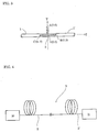
- 1 and 1' indicate the exposed portions of the optical fibers, in which the coatings of the optical fibers are removed, and 2 and 2' indicate optical fibers, 3 a fusion-spliced part, 4 arc electrodes, 5 electrode support stands, 6 an atmospheric gas exhaust pipes, 7 optical fiber holding stands, and 8 an electrode carrier, respectively.
- the direction of the opposing arc electrodes is indicated as X-axis
- the longitudinal axis of the optical fiber at the fusion-spliced part is indicated as Z-axis
- a direction perpendicular to the X-axis and the Z-axis is indicated as Y-axis.
- the exposed portion 1 and 1' of the optical fibers consist of silica glass, respectively, around which a UV-cured resin is provided such that optical fibers 2 and 2' are formed. Since the mode field diameters of the optical fibers 2 and 2' are different, or small if they are the same, simply fusion splicing the optical fiber 2 and the optical fiber 2' causes a large splicing loss.
- the coating of each end portion is removed to obtain the exposed portions 1 and 1' of the optical fiber, and the tips thereof are cut to have a mirror-like surface, butted together, and fusion spliced together by an arc discharge of the fusion splicing unit.
- the refractive index profiles of the optical fiber 2 and the optical fiber 2' are discontinuous at the fusion spliced part 3. That is, when their mode field diameters are different, the mode field diameters change abruptly even if the center of each core agrees. Also, when the mode field diameters are small, it is difficult to match the center of each core exactly although it is necessary to do so. Therefore, the splicing loss is large immediately after the fusion splicing.
- a single-mode optical fiber having a mode field diameter of about 12 ⁇ m, which is comparatively large, and a dispersion compensating optical fiber having a mode field diameter of about 4 ⁇ m - 5 ⁇ m, which is comparatively small, are fusion spliced together, the splicing loss is about 1.35 dB at the 1.55 ⁇ m wavelength immediately after the fusion-splicing.
- an electrode support stand 5, which supports an arc electrode 4 is mounted on an electrode carrier 8.
- the electrode carrier 8 is equipped with a 3-axis driving unit for X-axis, Y-axis, and Z-axis, it is possible to let the heating center position between the two arc electrodes 4 move in a desired direction. It is possible to let the heating center position move along the optical fiber by having the driving unit drive in the Z-axis direction. If Z-axis drive and Y-axis drive are performed at the same time, the heating center position can be made to move in a direction in the Y-Z plane.
- FIGS. 1B and 1 C are front views respectively showing an example of the movement course of the heating center position, Fig.1B showing an example of V-form movement and Fig. 1C showing an example of a straight line movement.
- ⁇ my be about 20° - 45 ° in the case of fusion-splicing a single-mode optical fiber having a mode field diameter of about 12 ⁇ m and a dispersion compensating optical fiber having a mode field diameter of about 4 ⁇ m - 5 ⁇ m and performing heat treatment thereat.
- This allows the mode field diameter to decrease gradually as it is more distanced from the fusion spliced part.
- the distance between the arc electrodes is about 3 mm and the extent of a high temperature zone at the center of the arc discharge is about 1 mm to 2 mm in diameter.
- Z is preferably determined according to a difference in the mode field diameter: Z should be large when the difference in the mode field diameter is large.
- the arc discharge is performed with a constant electric current, and the arc electrodes are moved at a constant velocity. However, in the case of Fig. 1B, their movement is stopped once in order to change the direction of the movement at Point O.
- the driving system of the electrode carrier 8 is controlled by a computer in a control unit (not illustrated). Because of timing by General Purpose Interface Bus (GPIB) and the backlash of the driving system, the velocity of the arc electrode movement before and after the stoppage becomes as shown in Fig. 2, and the period during which the arc electrodes cannot be moved at a constant velocity is about 580 ms, including a decelerating time, stoppage time, and accelerating time.
- GPS General Purpose Interface Bus
- the heat treatment work is conducted with heating temperatures of the arc discharge lowered at the vicinity of the heating part during the arc discharge by spouting an inert gas, such as argon gas, from an atmospheric gas exhaust pipe 6 that is provided concentrically relative to the arc electrodes 4.
- a housing may be provided to cover the whole heating unit.
- the heating center position is shifted in the order of Point P' (0, -Y, -Z) ⁇ Point O (0, 0, 0) ⁇ Point Q (0, Y, Z) by performing the driving of the electrode carrier 8 in both Y-axis and Z-axis directions at the same time.
- the movement of the arc electrodes is stopped once at Point O, and the electrodes move at a constant velocity except for Points O, P', Q.
- the arc discharge is performed by applying a constant electric current. In this manner, the heat treatment in the case of Fig. 1C can be made equal to that of Fig 1B.
- the movement course of Fig. 1C is a straight line. Therefore, in the case of Fig. 1C, the composition of the electrode carrier 8 can be simplified because a needed performance can be achieved with one driving axis just by adjusting the direction of the driving axis of the driving system of the electrode carrier 8 to the direction of a straight line beforehand.
- the arc electrodes are mounted on the electrode carrier and moved while the fusion-spliced optical fiber is fixed.
- the optical fiber holding stands that support an optical fiber may be mounted on a movable carrier, and the optical fiber may be moved.
- an arc unit used for fusion splicing may be used for heat treatment, but another arc unit may be used for heat treatment, because there are differences in the control systems between a unit used for fusion splicing and a unit used for heat treatment.
- Figure 4 schematically shows an optical transmission line 9 comprising the optical fibers 2 and 2' that are spliced together in accordance with the method described above.
- the X mark indicates the connection point.
- the optical transmission line 9 is provided between a transmitter 10 and a receiver 11.
- Example 1 The discharge electric currents between the arc electrodes 4 in Example 1, Example 2, and Comparative Example 1 were 13 mA, and during the heat treatments, the vicinity of the heating part was provided with an atmosphere of argon gas by flowing argon gas from the atmospheric gas exhaust pipe 6 at the flow rate of 300 milliliter-per-minute.
- Example 1 Comparative Velocity V y 3 3 3 (mm/s) V z 3 5 3 Pattern Figure 1A Figure 1B Figure 3 before heating 1.35 1.35 1.35 Loss (dB) 1 st 0.20 0.22 2.00 2 nd 0.15 0.17 over 20 3 rd 0.12 0.14 over 20
- Example 1 the splicing losses were reduced from 1.35 dB, which is the value before heat treatment, to about 0.12 dB - 0.14 dB by performing heat treatments about three times (one and half round-trips) in the movement course shown in Fig.1B.
Landscapes
- Physics & Mathematics (AREA)
- Engineering & Computer Science (AREA)
- Plasma & Fusion (AREA)
- General Physics & Mathematics (AREA)
- Optics & Photonics (AREA)
- Mechanical Coupling Of Light Guides (AREA)
Applications Claiming Priority (2)
| Application Number | Priority Date | Filing Date | Title |
|---|---|---|---|
| JP2001048500A JP2002250836A (ja) | 2001-02-23 | 2001-02-23 | 光ファイバの融着接続方法 |
| JP2001048500 | 2001-02-23 |
Publications (3)
| Publication Number | Publication Date |
|---|---|
| EP1235085A2 true EP1235085A2 (fr) | 2002-08-28 |
| EP1235085A3 EP1235085A3 (fr) | 2004-03-10 |
| EP1235085B1 EP1235085B1 (fr) | 2005-11-23 |
Family
ID=18909755
Family Applications (1)
| Application Number | Title | Priority Date | Filing Date |
|---|---|---|---|
| EP02003279A Expired - Lifetime EP1235085B1 (fr) | 2001-02-23 | 2002-02-22 | Procédé de soudure pour fibres optiques et ligne de transmission à fibre optique |
Country Status (6)
| Country | Link |
|---|---|
| US (1) | US6854293B2 (fr) |
| EP (1) | EP1235085B1 (fr) |
| JP (1) | JP2002250836A (fr) |
| AU (1) | AU1542102A (fr) |
| DE (1) | DE60207457T2 (fr) |
| DK (1) | DK1235085T3 (fr) |
Cited By (1)
| Publication number | Priority date | Publication date | Assignee | Title |
|---|---|---|---|---|
| EP1260840A3 (fr) * | 2001-05-22 | 2004-10-20 | Sumitomo Electric Industries, Ltd. | Méthode d'épisser des fibres optiques par fusion et dispositif pour chauffer l'épissure par l'arc |
Families Citing this family (4)
| Publication number | Priority date | Publication date | Assignee | Title |
|---|---|---|---|---|
| US6991383B2 (en) * | 2003-09-18 | 2006-01-31 | Telefonaktiebolaget Lm Ericsson (Publ) | Fusion splicing of highly rare-earth-doped optical fibers |
| WO2012098681A1 (fr) * | 2011-01-21 | 2012-07-26 | 株式会社フジクラ | Procédé et dispositif pour imposer une décharge électrique sur une fibre optique |
| US10641960B1 (en) * | 2018-10-04 | 2020-05-05 | The United States Of America As Represented By The Secretary Of The Navy | Method and apparatus for assembling a fiber optic splice |
| US12181712B2 (en) * | 2019-08-29 | 2024-12-31 | Sumitomo Electric Optifrontier Co., Ltd. | Fusion splicing device and method for operating fusion splicing device with electrode discharge test, evaluation, and adjustment |
Family Cites Families (13)
| Publication number | Priority date | Publication date | Assignee | Title |
|---|---|---|---|---|
| US4557556A (en) * | 1983-10-28 | 1985-12-10 | At&T Bell Laboratories | Method of fabricating an optical attenuator by fusion splicing of optical fibers |
| US4948412A (en) * | 1985-09-16 | 1990-08-14 | Fujikura Ltd. | Method of fusion splicing single-mode optical fibers using an arc discharge |
| DE3726607A1 (de) * | 1987-08-11 | 1989-02-23 | Philips Patentverwaltung | Verfahren zum gleichzeitigen verschweissen mehrerer lichtwellenleiterpaare |
| JPH01284806A (ja) * | 1988-05-12 | 1989-11-16 | Fujitsu Ltd | 光ファイバ表面傷の消去方法 |
| JPH0572439A (ja) * | 1991-09-18 | 1993-03-26 | Hitachi Cable Ltd | 導波路系と光学系との融着接続方法及びその装置 |
| US6120192A (en) | 1995-06-07 | 2000-09-19 | Siemens Aktiengesellschaft | Splicing means for welding light waveguides |
| FR2777273B1 (fr) * | 1998-04-09 | 2000-05-12 | Alsthom Cge Alcatel | Soudage bout a bout de preformes de fibres optiques a l'aide d'une torche a plasma |
| JP3398046B2 (ja) | 1998-04-24 | 2003-04-21 | 古河電気工業株式会社 | 光ファイバケーブル用スロットロッド |
| JPH11305065A (ja) * | 1998-04-24 | 1999-11-05 | Furukawa Electric Co Ltd:The | 光ファイバの融着接続方法 |
| JP3746619B2 (ja) * | 1998-09-25 | 2006-02-15 | 株式会社フジクラ | 光ファイバの融着接続方法 |
| JP2003057481A (ja) * | 2001-06-06 | 2003-02-26 | Fujikura Ltd | 光ファイバ融着接続機および光ファイバ融着接続法 |
| JP2003315599A (ja) * | 2002-04-22 | 2003-11-06 | Sumitomo Electric Ind Ltd | 多心光ファイバの放電加熱方法および加熱装置 |
| US7037003B2 (en) * | 2002-11-12 | 2006-05-02 | Fitel Usa Corp. | Systems and methods for reducing splice loss in optical fibers |
-
2001
- 2001-02-23 JP JP2001048500A patent/JP2002250836A/ja active Pending
-
2002
- 2002-02-05 AU AU15421/02A patent/AU1542102A/en not_active Abandoned
- 2002-02-11 US US10/068,852 patent/US6854293B2/en not_active Expired - Lifetime
- 2002-02-22 EP EP02003279A patent/EP1235085B1/fr not_active Expired - Lifetime
- 2002-02-22 DK DK02003279T patent/DK1235085T3/da active
- 2002-02-22 DE DE60207457T patent/DE60207457T2/de not_active Expired - Lifetime
Cited By (2)
| Publication number | Priority date | Publication date | Assignee | Title |
|---|---|---|---|---|
| EP1260840A3 (fr) * | 2001-05-22 | 2004-10-20 | Sumitomo Electric Industries, Ltd. | Méthode d'épisser des fibres optiques par fusion et dispositif pour chauffer l'épissure par l'arc |
| US6886998B2 (en) | 2001-05-22 | 2005-05-03 | Sumitomo Electric Industries, Ltd. | Method for fusion splicing optical fibers and apparatus for heating spliced part by arc |
Also Published As
| Publication number | Publication date |
|---|---|
| US6854293B2 (en) | 2005-02-15 |
| US20020157424A1 (en) | 2002-10-31 |
| EP1235085B1 (fr) | 2005-11-23 |
| DK1235085T3 (da) | 2006-03-20 |
| JP2002250836A (ja) | 2002-09-06 |
| DE60207457D1 (de) | 2005-12-29 |
| EP1235085A3 (fr) | 2004-03-10 |
| DE60207457T2 (de) | 2006-08-03 |
| AU1542102A (en) | 2002-11-14 |
Similar Documents
| Publication | Publication Date | Title |
|---|---|---|
| EP0144136B1 (fr) | Procédé de fabrication d'un atténuateur optiqe par raccordement par fusion de fibres optiques | |
| EP0423999B1 (fr) | Procédé d'agrandissement de l'ouverture située à l'extrémité d'un tube capillaire | |
| US4118618A (en) | Device for welding optical fibres end to end | |
| CA2179565A1 (fr) | Couplage de fibres optiques, connecteur pour fibres optiques et procede de fabrication | |
| EP1293812B1 (fr) | Appareil et méthode pour chauffer une fibre optique par décharge électrique | |
| US20130292859A1 (en) | Optical fiber end processing method and optical fiber end processing apparatus | |
| EP1235085B1 (fr) | Procédé de soudure pour fibres optiques et ligne de transmission à fibre optique | |
| US20020009271A1 (en) | Method and apparatus for splicing optical fibers | |
| JP2618500B2 (ja) | 光ファイバ接続方法 | |
| KR20040057912A (ko) | 스폿 사이즈 변환용 광섬유 부품 및 그의 제조방법 | |
| US6565269B2 (en) | Systems and methods for low-loss splicing of optical fibers having a high concentration of fluorine to other types of optical fiber | |
| JP2000098171A (ja) | 光ファイバの融着接続方法 | |
| JPH11305065A (ja) | 光ファイバの融着接続方法 | |
| JP3344061B2 (ja) | 光ファイバの融着接続方法 | |
| EP1343035B1 (fr) | Dispositif pour épissurer à perte basse des fibres optiques ayant une concentration en fluor élevée avec d'autres types de fibre optique | |
| EP0687930B1 (fr) | Méthode de fabrication de coupleurs à fibres optiques | |
| JPH01283507A (ja) | 光部品の調心方法 | |
| JP3786794B2 (ja) | 光ファイバ融着接続機 | |
| JP2771737B2 (ja) | コア拡大光ファイバの作製方法 | |
| JP2003075676A (ja) | 光ファイバ融着接続方法 | |
| JPH0675140A (ja) | 光ファイバカプラの製造方法 | |
| JPH0943445A (ja) | 光ファイバ支持体 | |
| JPS62262005A (ja) | 光集束型ロツドレンズ | |
| JPH04268507A (ja) | 光ファイバの接合が容易な光通信用部品 | |
| JPH027008A (ja) | 光ファイバカップラ製造装置 |
Legal Events
| Date | Code | Title | Description |
|---|---|---|---|
| PUAI | Public reference made under article 153(3) epc to a published international application that has entered the european phase |
Free format text: ORIGINAL CODE: 0009012 |
|
| AK | Designated contracting states |
Kind code of ref document: A2 Designated state(s): AT BE CH CY DE DK ES FI FR GB GR IE IT LI LU MC NL PT SE TR |
|
| AX | Request for extension of the european patent |
Free format text: AL;LT;LV;MK;RO;SI |
|
| PUAL | Search report despatched |
Free format text: ORIGINAL CODE: 0009013 |
|
| AK | Designated contracting states |
Kind code of ref document: A3 Designated state(s): AT BE CH CY DE DK ES FI FR GB GR IE IT LI LU MC NL PT SE TR |
|
| AX | Request for extension of the european patent |
Extension state: AL LT LV MK RO SI |
|
| 17P | Request for examination filed |
Effective date: 20040303 |
|
| 17Q | First examination report despatched |
Effective date: 20040507 |
|
| AKX | Designation fees paid |
Designated state(s): DE DK FR GB IT |
|
| GRAP | Despatch of communication of intention to grant a patent |
Free format text: ORIGINAL CODE: EPIDOSNIGR1 |
|
| GRAS | Grant fee paid |
Free format text: ORIGINAL CODE: EPIDOSNIGR3 |
|
| GRAA | (expected) grant |
Free format text: ORIGINAL CODE: 0009210 |
|
| AK | Designated contracting states |
Kind code of ref document: B1 Designated state(s): DE DK FR GB IT |
|
| REG | Reference to a national code |
Ref country code: GB Ref legal event code: FG4D |
|
| REF | Corresponds to: |
Ref document number: 60207457 Country of ref document: DE Date of ref document: 20051229 Kind code of ref document: P |
|
| REG | Reference to a national code |
Ref country code: DK Ref legal event code: T3 |
|
| ET | Fr: translation filed | ||
| PLBE | No opposition filed within time limit |
Free format text: ORIGINAL CODE: 0009261 |
|
| STAA | Information on the status of an ep patent application or granted ep patent |
Free format text: STATUS: NO OPPOSITION FILED WITHIN TIME LIMIT |
|
| 26N | No opposition filed |
Effective date: 20060824 |
|
| REG | Reference to a national code |
Ref country code: FR Ref legal event code: PLFP Year of fee payment: 15 |
|
| PGFP | Annual fee paid to national office [announced via postgrant information from national office to epo] |
Ref country code: DE Payment date: 20160216 Year of fee payment: 15 Ref country code: IT Payment date: 20160222 Year of fee payment: 15 Ref country code: DK Payment date: 20160210 Year of fee payment: 15 |
|
| PGFP | Annual fee paid to national office [announced via postgrant information from national office to epo] |
Ref country code: GB Payment date: 20160217 Year of fee payment: 15 Ref country code: FR Payment date: 20160108 Year of fee payment: 15 |
|
| REG | Reference to a national code |
Ref country code: DE Ref legal event code: R119 Ref document number: 60207457 Country of ref document: DE |
|
| REG | Reference to a national code |
Ref country code: DK Ref legal event code: EBP Effective date: 20170228 |
|
| GBPC | Gb: european patent ceased through non-payment of renewal fee |
Effective date: 20170222 |
|
| REG | Reference to a national code |
Ref country code: FR Ref legal event code: ST Effective date: 20171031 |
|
| PG25 | Lapsed in a contracting state [announced via postgrant information from national office to epo] |
Ref country code: FR Free format text: LAPSE BECAUSE OF NON-PAYMENT OF DUE FEES Effective date: 20170228 Ref country code: DK Free format text: LAPSE BECAUSE OF NON-PAYMENT OF DUE FEES Effective date: 20170228 Ref country code: DE Free format text: LAPSE BECAUSE OF NON-PAYMENT OF DUE FEES Effective date: 20170901 |
|
| PG25 | Lapsed in a contracting state [announced via postgrant information from national office to epo] |
Ref country code: IT Free format text: LAPSE BECAUSE OF NON-PAYMENT OF DUE FEES Effective date: 20170222 Ref country code: GB Free format text: LAPSE BECAUSE OF NON-PAYMENT OF DUE FEES Effective date: 20170222 |