EP1235157A2 - Périphérique comprenant un connecteur d'expansion attachable à un dispositif hôte - Google Patents
Périphérique comprenant un connecteur d'expansion attachable à un dispositif hôte Download PDFInfo
- Publication number
- EP1235157A2 EP1235157A2 EP02251019A EP02251019A EP1235157A2 EP 1235157 A2 EP1235157 A2 EP 1235157A2 EP 02251019 A EP02251019 A EP 02251019A EP 02251019 A EP02251019 A EP 02251019A EP 1235157 A2 EP1235157 A2 EP 1235157A2
- Authority
- EP
- European Patent Office
- Prior art keywords
- plug
- interface
- circuit
- connector
- interface connector
- Prior art date
- Legal status (The legal status is an assumption and is not a legal conclusion. Google has not performed a legal analysis and makes no representation as to the accuracy of the status listed.)
- Granted
Links
Images




Classifications
-
- G—PHYSICS
- G06—COMPUTING OR CALCULATING; COUNTING
- G06F—ELECTRIC DIGITAL DATA PROCESSING
- G06F1/00—Details not covered by groups G06F3/00 - G06F13/00 and G06F21/00
- G06F1/16—Constructional details or arrangements
- G06F1/1613—Constructional details or arrangements for portable computers
- G06F1/1632—External expansion units, e.g. docking stations
-
- G—PHYSICS
- G06—COMPUTING OR CALCULATING; COUNTING
- G06F—ELECTRIC DIGITAL DATA PROCESSING
- G06F1/00—Details not covered by groups G06F3/00 - G06F13/00 and G06F21/00
- G06F1/26—Power supply means, e.g. regulation thereof
- G06F1/266—Arrangements to supply power to external peripherals either directly from the computer or under computer control, e.g. supply of power through the communication port, computer controlled power-strips
-
- G—PHYSICS
- G06—COMPUTING OR CALCULATING; COUNTING
- G06F—ELECTRIC DIGITAL DATA PROCESSING
- G06F13/00—Interconnection of, or transfer of information or other signals between, memories, input/output devices or central processing units
- G06F13/38—Information transfer, e.g. on bus
- G06F13/40—Bus structure
- G06F13/4063—Device-to-bus coupling
- G06F13/409—Mechanical coupling
-
- H—ELECTRICITY
- H01—ELECTRIC ELEMENTS
- H01R—ELECTRICALLY-CONDUCTIVE CONNECTIONS; STRUCTURAL ASSOCIATIONS OF A PLURALITY OF MUTUALLY-INSULATED ELECTRICAL CONNECTING ELEMENTS; COUPLING DEVICES; CURRENT COLLECTORS
- H01R13/00—Details of coupling devices of the kinds covered by groups H01R12/70 or H01R24/00 - H01R33/00
- H01R13/66—Structural association with built-in electrical component
- H01R13/665—Structural association with built-in electrical component with built-in electronic circuit
-
- H—ELECTRICITY
- H01—ELECTRIC ELEMENTS
- H01R—ELECTRICALLY-CONDUCTIVE CONNECTIONS; STRUCTURAL ASSOCIATIONS OF A PLURALITY OF MUTUALLY-INSULATED ELECTRICAL CONNECTING ELEMENTS; COUPLING DEVICES; CURRENT COLLECTORS
- H01R13/00—Details of coupling devices of the kinds covered by groups H01R12/70 or H01R24/00 - H01R33/00
- H01R13/66—Structural association with built-in electrical component
- H01R13/70—Structural association with built-in electrical component with built-in switch
-
- H—ELECTRICITY
- H01—ELECTRIC ELEMENTS
- H01R—ELECTRICALLY-CONDUCTIVE CONNECTIONS; STRUCTURAL ASSOCIATIONS OF A PLURALITY OF MUTUALLY-INSULATED ELECTRICAL CONNECTING ELEMENTS; COUPLING DEVICES; CURRENT COLLECTORS
- H01R2201/00—Connectors or connections adapted for particular applications
- H01R2201/06—Connectors or connections adapted for particular applications for computer periphery
Definitions
- the present invention relates a peripheral with expansion connector attachable to a host, and more particularly, to one provided with input for dedicated interface circuit to couple to the host and an selection switch to switch between input contact and output connector.
- the prior art of a peripheral attachable to a computer host must be removed when connection to any other interface is required.
- the present invention of a peripheral is provided with additional expansion connector and a selection switch so to make connection with other interface for the host possible without removing the peripheral using the expansion connector.
- the present invention relates to a peripheral provided with expansion connector attachable to a host and contains an interface connector (or a plug-socket unit) P1 to be connected to an interface connector (or a plug-socket unit) P0 from the host, a subsidiary I/O interface connector (or plug-socket unit) P2; a dedicated interface circuit C100 and an selection switch SL100 to conduct through said interface connector (or plug-socket unit) P1 either to said dedicated interface circuit C100 or the subsidiary I/O interface connector (or the plug-socket unit)P2.
- a peripheral provided with expansion connector attachable to a host of the present invention is essentially comprised of a wired peripheral provided with an interface connector (or a plug-socket unit) P1 connected to an interface connector (or a plug-socket unit) P0 from the host, and the peripheral is attachable or detachable to and from the host by means of a tennon, screw, or magnet structure.
- a subsidiary I/O interface connector (or plug-socket unit) P2, a dedicated interface circuit C100 and an selection switch SL100 to conduct through said interface connector (or plug-socket unit) P1 and said dedicated interface circuit C100 are provided inside the peripheral.
- the P1 When said P1 and C100 are conducted through, the P1 is disconnected from said subsidiary I/O interface connector (or plug-socket unit) P2 to drive the corresponding dedicated interface circuit C100; or to conduct through the interface connector (or plug-socket unit) P1 and the subsidiary I/O interface connector (or plug-socket unit) P2 by switching, thus to disconnect from the dedicated interface circuit C100. Consequently, the interface connector (or plug-socket unit) P0 from the host passes through the subsidiary I/O interface connector (or plug-socket unit) P2 via the interface connector (or plug-socket unit) P1 and the selection switch SL100.
- the peripheral provided with expansion connector attachable to the host relates to a wired peripheral that can be attached to or detached from the host by means of a tennon, screw or magnetic structure.
- the peripheral is essentially comprised of an interface connector (or a plug-socket set) P1 coupled to an interface connector (or a plug-socket set) P0 from the host; one or more than one set of subsidiary I/O interface connector (or plug-socket unit) P2 and a selection switch SL 100 for the interface connector (or the plug-socket unit) P1 to connect through the subsidiary I/O interface connector (or the plug-socket unit) P2 or for the interface connector (or the plug-socket unit) P1 to connect through the dedicated interface circuit C100.
- Fig. 1 showing a block chart of a basic circuit of the peripheral provided with expansion connector attachable to the host is essentially comprised of a housing HS100, made of plastic by molding injection, or cast alloy or metallic material or other materials to accommodate the dedicated circuit C100, the interface connector (or the plug-socket unit) P1, one or more than one set of subsidiary I/O interface connector (or the plug-socket unit) P2, and the selection switch SL100 for the interface connector (or the plug-socket unit) P1 to select to connect through the dedicated circuit C100, the interface connector (or the plug-socket unit) P1, or to the subsidiary I/O interface connector (or the plug-socket unit) P2; and a tennon, screw or magnet structure for the peripheral to be incorporated to the host.
- a housing HS100 made of plastic by molding injection, or cast alloy or metallic material or other materials to accommodate the dedicated circuit C100, the interface connector (or the plug-socket unit) P1, one or more than
- said interface connector (or the plug-socket unit) P1 is comprised of one that meets the specification of SERIAL, PS2, USB, IEEE1394 or other selected specification for connection to the interface connector (or the plug-socket unit) P0 from the host.
- the dedicated interface C100 relates to a solid-state electronic circuit or electromechanical circuit, such as a receiving circuit functioning as a receiver or other interface circuit dedicated to the peripheral.
- the subsidiary I/O interface connector (or the plug-socket unit) P2 relates to one or more than one set of connector meeting SERIAL, PS2, USB, IEEE1394 or other selected specifications to connect to other wired peripheral.
- the selection switch SL100 relates a distributed type of selection switch comprised of electromechanical or solid-state circuit device to switch the interface connector (or the plug-socket) P1 to connect to the dedicated interface circuit C100 or to the subsidiary I/O interface connector (or the plug-socket unit) P2.
- the selection switch SL100 may be or may not be provided.
- an additional charging set can be provided to the peripheral provided with expansion connector that can be attached to the host, so to take advantage of the power supply from the host to charge itself for the use by any adapted wireless device.
- Fig. 2 shows a schematic view of a preferred embodiment of the present invention provided with a concurrent charging set
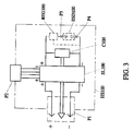
- Fig. 3 shows a block chart of a circuit layout of the present invention.
- both of positive and negative sources in the dedicated interface circuit C100 are made in series (or in parallel) to provide a charging control and display circuit REG100 comprised of an electromechanical or solid-state electronic device.
- the circuit REG100 is further made in parallel with charging connectors (or plug-socket units) P3 and P4 for the circuit of the same polarity to become in parallel and be placed into a battery unit ESD100 comprised of a recharging and discharging secondary battery, or capacitor or ultra-capacitor.
- Said ESD100 to receive power supplied from the host, to operate and control of charging voltage/current, and to display its charging status.
- Fig. 4 shows an elevation view of the appearance of the present invention
- Fig. 5 is a view showing an example of a circuit of a voltage regulator of the present invention.
- a zener diode ZD101 is directly connected in series with an output end with the zener voltage functioning as a drop value between the source and the output interface.
- the purpose can be also achieved, as illustrated in Fig. 6, showing another example of a voltage regulator circuit, which is capable of light emitting and drop, of the present invention.
- the zener diode ZD101 (or more than one zener diodes ZD101 connected in series or parallel), the light emitting diode LED101 (or more than one light emitting diodes connected in series or parallel) with illumination and drop effects and the limit resistance R102 are connected in series.
- an additional diode CR101 for separation may be added also in series at the input end.
- a charging status display circuit comprised of a light emitting diode LED102 and a limit resistance R102 to be connected at the output end for drop and charging status display.
- a voltage regulator for stabilized voltage output of the present invention is comprised of the limit resistance R101 and the zener diode ZD101.
- the limit resistance R101 is connected in series between the source and the output interface while the zener diode ZD101 is connected in parallel between both ends of the output interface for to output stabilized voltage.
- the separation diode CR101 may be added at the input end or a charging status display circuit, comprised of the light emitting diode LED102 and the limit resistance R102 connected in series, may be connected in parallel at the output end.
- the peripheral with expansion connector that is attachable to the host of the present invention as disclosed above provides flexible adaptation and fixation of the subsidiary I/O interface connector (or the plug-socket unit) to facilitate its control and operation without having to always carry it along when not used.
Landscapes
- Engineering & Computer Science (AREA)
- Theoretical Computer Science (AREA)
- General Engineering & Computer Science (AREA)
- Computer Hardware Design (AREA)
- Physics & Mathematics (AREA)
- General Physics & Mathematics (AREA)
- Human Computer Interaction (AREA)
- Details Of Connecting Devices For Male And Female Coupling (AREA)
- Power Sources (AREA)
- Charge And Discharge Circuits For Batteries Or The Like (AREA)
- Casings For Electric Apparatus (AREA)
- Information Transfer Systems (AREA)
Applications Claiming Priority (6)
| Application Number | Priority Date | Filing Date | Title |
|---|---|---|---|
| TW090101831A TWI282647B (en) | 2001-01-30 | 2001-01-30 | An accessory with expanding joints for being mounted on a mainframe |
| US791823 | 2001-02-26 | ||
| US09/791,823 US6527560B2 (en) | 2001-01-30 | 2001-02-26 | Peripheral with expansion connector attachable to host |
| CN01109379.XA CN1274067C (zh) | 2001-01-30 | 2001-03-02 | 固定在主机外且具有扩充接头的装置 |
| CN01207432.2U CN2472370Y (zh) | 2001-01-30 | 2001-03-02 | 固定在主机外且具有扩充接头的装置 |
| JP2001111526A JP4615757B2 (ja) | 2001-01-30 | 2001-04-10 | 主フレームに設置可能な周辺装置 |
Publications (3)
| Publication Number | Publication Date |
|---|---|
| EP1235157A2 true EP1235157A2 (fr) | 2002-08-28 |
| EP1235157A3 EP1235157A3 (fr) | 2005-07-13 |
| EP1235157B1 EP1235157B1 (fr) | 2011-08-10 |
Family
ID=50481644
Family Applications (1)
| Application Number | Title | Priority Date | Filing Date |
|---|---|---|---|
| EP02251019A Expired - Lifetime EP1235157B1 (fr) | 2001-01-30 | 2002-02-14 | Périphérique comprenant un connecteur d'expansion attachable à un dispositif hôte |
Country Status (6)
| Country | Link |
|---|---|
| US (1) | US6527560B2 (fr) |
| EP (1) | EP1235157B1 (fr) |
| JP (1) | JP4615757B2 (fr) |
| CN (2) | CN1274067C (fr) |
| AT (1) | ATE520084T1 (fr) |
| TW (1) | TWI282647B (fr) |
Cited By (1)
| Publication number | Priority date | Publication date | Assignee | Title |
|---|---|---|---|---|
| WO2005076145A1 (fr) * | 2004-02-05 | 2005-08-18 | Robert Bosch Gmbh | Unite receptrice pour une barrette de memoire et appareil electronique comprenant une unite receptrice pour une barrette de memoire |
Families Citing this family (8)
| Publication number | Priority date | Publication date | Assignee | Title |
|---|---|---|---|---|
| US6449680B1 (en) * | 1999-02-12 | 2002-09-10 | Compaq Computer Corporation | Combined single-ended/differential data bus connector |
| US20070154889A1 (en) * | 2004-06-25 | 2007-07-05 | Veridex, Llc | Methods and reagents for the detection of melanoma |
| TWM266618U (en) * | 2004-07-19 | 2005-06-01 | Behavior Tech Computer Corp | Multiple output connection head with wireless data collection capability |
| JP2007148715A (ja) * | 2005-11-28 | 2007-06-14 | Smk Corp | データ入力端末装置 |
| US9300081B2 (en) | 2010-02-02 | 2016-03-29 | Charles Albert Rudisill | Interposer connectors with magnetic components |
| CN103775797B (zh) * | 2012-10-26 | 2016-03-30 | 英业达科技有限公司 | 具有扩充功能的容置装置 |
| US10680383B2 (en) | 2013-03-14 | 2020-06-09 | Apex Technologies, Inc. | Linear electrode systems for module attachment with non-uniform axial spacing |
| CN106486851B (zh) * | 2015-08-28 | 2019-05-14 | 富士康(昆山)电脑接插件有限公司 | 线缆连接器组件 |
Family Cites Families (21)
| Publication number | Priority date | Publication date | Assignee | Title |
|---|---|---|---|---|
| US4744006A (en) * | 1986-07-10 | 1988-05-10 | Duffield Robert H | Apparatus for expanding the input/output capabilities of a personal computer |
| JPS6446820A (en) * | 1987-08-17 | 1989-02-21 | Oki Electric Ind Co Ltd | Interface switching system |
| WO1994016387A1 (fr) * | 1993-01-04 | 1994-07-21 | Coactive Computing Corporation | Dispositif d'interface d'ordinateur servant a communiquer avec un dispositif peripherique et un reseau |
| JPH06301455A (ja) * | 1993-04-09 | 1994-10-28 | Citizen Watch Co Ltd | 携帯型パーソナルコンピュータ |
| JPH06332591A (ja) * | 1993-05-18 | 1994-12-02 | Seiko Epson Corp | ディスプレイ |
| US5592362A (en) * | 1993-10-29 | 1997-01-07 | Kabushiki Kaisha Toshiba | Electronic system having portable electronic apparatus and external expansion unit for expanding function of electronic apparatus |
| US5459637A (en) * | 1993-12-06 | 1995-10-17 | Ma; Hsi K. | Portable notebook computer expansion adapter |
| US5689400A (en) * | 1994-05-31 | 1997-11-18 | Kabushiki Kaisha Toshiba | Portable electronic apparatus including space-saving component mounting features |
| US5796579A (en) * | 1994-05-31 | 1998-08-18 | Kabushiki Kaisha Toshiba | Portable electronic apparatus having expansion connector covered by pivotally mounted upper and lower covers having laterally extending guide portions |
| NL9400967A (nl) * | 1994-06-14 | 1996-01-02 | Tulip Computers International | Moederbord voor een computer van het AT-type, alsmede een computer van het AT-type, voorzien van een dergelijk moederbord. |
| JPH09128317A (ja) * | 1995-10-27 | 1997-05-16 | Matsushita Electric Ind Co Ltd | 画像入力装置 |
| CN2246821Y (zh) * | 1995-11-13 | 1997-02-05 | 马希光 | 笔记型电脑用扩充盒 |
| CN2247830Y (zh) * | 1995-11-13 | 1997-02-19 | 马希光 | 具嵌入式扩充装置的笔记本型电脑 |
| US6008985A (en) * | 1995-11-20 | 1999-12-28 | The Foxboro Company | Industrial field controlling device with controller and expansion modules |
| JPH1039945A (ja) * | 1996-07-18 | 1998-02-13 | Toshiba Corp | コンピュータシステム及び同システムに適用する拡張ユニット |
| JPH11202993A (ja) * | 1998-01-19 | 1999-07-30 | Canon Inc | 通信アダプタ及びデータ通信システム |
| US5920177A (en) * | 1998-02-24 | 1999-07-06 | 3Com Corporation | Autonomously powered communications card modem having additional communications port for use as an external modem |
| JP2000222336A (ja) * | 1999-02-01 | 2000-08-11 | Canon Inc | データ転送装置、データ転送方法及びデータ処理装置 |
| JP2003233579A (ja) * | 2002-02-08 | 2003-08-22 | Canon Inc | 記憶装置および処理方法 |
| JP2004192132A (ja) * | 2002-12-09 | 2004-07-08 | Matsushita Electric Ind Co Ltd | インターフェース変換装置 |
| JP4504666B2 (ja) * | 2003-12-09 | 2010-07-14 | 株式会社アイ・オー・データ機器 | 周辺装置、および再接続プログラム |
-
2001
- 2001-01-30 TW TW090101831A patent/TWI282647B/zh not_active IP Right Cessation
- 2001-02-26 US US09/791,823 patent/US6527560B2/en not_active Expired - Lifetime
- 2001-03-02 CN CN01109379.XA patent/CN1274067C/zh not_active Expired - Fee Related
- 2001-03-02 CN CN01207432.2U patent/CN2472370Y/zh not_active Expired - Lifetime
- 2001-04-10 JP JP2001111526A patent/JP4615757B2/ja not_active Expired - Fee Related
-
2002
- 2002-02-14 AT AT02251019T patent/ATE520084T1/de not_active IP Right Cessation
- 2002-02-14 EP EP02251019A patent/EP1235157B1/fr not_active Expired - Lifetime
Cited By (1)
| Publication number | Priority date | Publication date | Assignee | Title |
|---|---|---|---|---|
| WO2005076145A1 (fr) * | 2004-02-05 | 2005-08-18 | Robert Bosch Gmbh | Unite receptrice pour une barrette de memoire et appareil electronique comprenant une unite receptrice pour une barrette de memoire |
Also Published As
| Publication number | Publication date |
|---|---|
| CN1373536A (zh) | 2002-10-09 |
| EP1235157B1 (fr) | 2011-08-10 |
| US20020119705A1 (en) | 2002-08-29 |
| JP4615757B2 (ja) | 2011-01-19 |
| JP2002312088A (ja) | 2002-10-25 |
| US6527560B2 (en) | 2003-03-04 |
| ATE520084T1 (de) | 2011-08-15 |
| EP1235157A3 (fr) | 2005-07-13 |
| CN2472370Y (zh) | 2002-01-16 |
| CN1274067C (zh) | 2006-09-06 |
| TWI282647B (en) | 2007-06-11 |
Similar Documents
| Publication | Publication Date | Title |
|---|---|---|
| US9028122B2 (en) | Lighted electrical connector assembly | |
| US8253277B2 (en) | Electronic assembly provided with a parallel circuit for connecting electrically to two battery units | |
| CN1913216B (zh) | 由电器主机电源供电的备用电池座 | |
| US20080012423A1 (en) | USB connector devices for charging | |
| US20130065444A1 (en) | Charging connection device with illumination and associated methods | |
| US20070126290A1 (en) | Systems and methods for powering an electronic device from selectable power sources | |
| US11374367B2 (en) | Vibrating connector system | |
| GB2557148A (en) | Electrical connectors | |
| JP2011041394A (ja) | 接続装置 | |
| EP1235157A2 (fr) | Périphérique comprenant un connecteur d'expansion attachable à un dispositif hôte | |
| US20080002509A1 (en) | Power adapter with discriminate recharging | |
| US20080012524A1 (en) | Chargeable electronic devices and direct current voltage supply systems | |
| US10713200B2 (en) | USB adapter and cable | |
| CN116940256A (zh) | 用于气溶胶产生装置的扩展单元 | |
| CN205646382U (zh) | 一种数据线组件及充电器组件 | |
| CN204333492U (zh) | 一种带灯并开关可控的USB Type-C照明数据线 | |
| CN206331538U (zh) | 手持pos终端及其usb切换电路 | |
| US11088572B2 (en) | Detachable charging pad | |
| US20140210719A1 (en) | Wireless input device | |
| CN220342491U (zh) | 一种照明装置 | |
| US20140361731A1 (en) | Vehicle-mounted charging device | |
| CN221447629U (zh) | 跑马灯数据线 | |
| CN210780573U (zh) | 一种便捷安装新型通用电源适配器 | |
| GB2404292A (en) | Voltage adaptor with removable voltage setting element | |
| CN102541666B (zh) | 一种电子设备和保护电子设备内部器件的方法 |
Legal Events
| Date | Code | Title | Description |
|---|---|---|---|
| PUAI | Public reference made under article 153(3) epc to a published international application that has entered the european phase |
Free format text: ORIGINAL CODE: 0009012 |
|
| AK | Designated contracting states |
Kind code of ref document: A2 Designated state(s): AT BE CH CY DE DK ES FI FR GB GR IE IT LI LU MC NL PT SE TR |
|
| AX | Request for extension of the european patent |
Free format text: AL;LT;LV;MK;RO;SI |
|
| PUAL | Search report despatched |
Free format text: ORIGINAL CODE: 0009013 |
|
| AK | Designated contracting states |
Kind code of ref document: A3 Designated state(s): AT BE CH CY DE DK ES FI FR GB GR IE IT LI LU MC NL PT SE TR |
|
| AX | Request for extension of the european patent |
Extension state: AL LT LV MK RO SI |
|
| 17P | Request for examination filed |
Effective date: 20060109 |
|
| AKX | Designation fees paid |
Designated state(s): AT BE CH CY DE DK ES FI FR GB GR IE IT LI LU MC NL PT SE TR |
|
| 17Q | First examination report despatched |
Effective date: 20060703 |
|
| GRAP | Despatch of communication of intention to grant a patent |
Free format text: ORIGINAL CODE: EPIDOSNIGR1 |
|
| GRAS | Grant fee paid |
Free format text: ORIGINAL CODE: EPIDOSNIGR3 |
|
| GRAA | (expected) grant |
Free format text: ORIGINAL CODE: 0009210 |
|
| AK | Designated contracting states |
Kind code of ref document: B1 Designated state(s): AT BE CH CY DE DK ES FI FR GB GR IE IT LI LU MC NL PT SE TR |
|
| REG | Reference to a national code |
Ref country code: GB Ref legal event code: FG4D |
|
| REG | Reference to a national code |
Ref country code: CH Ref legal event code: EP |
|
| REG | Reference to a national code |
Ref country code: IE Ref legal event code: FG4D |
|
| REG | Reference to a national code |
Ref country code: DE Ref legal event code: R096 Ref document number: 60240723 Country of ref document: DE Effective date: 20111013 |
|
| REG | Reference to a national code |
Ref country code: NL Ref legal event code: T3 |
|
| PG25 | Lapsed in a contracting state [announced via postgrant information from national office to epo] |
Ref country code: SE Free format text: LAPSE BECAUSE OF FAILURE TO SUBMIT A TRANSLATION OF THE DESCRIPTION OR TO PAY THE FEE WITHIN THE PRESCRIBED TIME-LIMIT Effective date: 20110810 Ref country code: FI Free format text: LAPSE BECAUSE OF FAILURE TO SUBMIT A TRANSLATION OF THE DESCRIPTION OR TO PAY THE FEE WITHIN THE PRESCRIBED TIME-LIMIT Effective date: 20110810 Ref country code: PT Free format text: LAPSE BECAUSE OF FAILURE TO SUBMIT A TRANSLATION OF THE DESCRIPTION OR TO PAY THE FEE WITHIN THE PRESCRIBED TIME-LIMIT Effective date: 20111212 |
|
| REG | Reference to a national code |
Ref country code: AT Ref legal event code: MK05 Ref document number: 520084 Country of ref document: AT Kind code of ref document: T Effective date: 20110810 |
|
| PG25 | Lapsed in a contracting state [announced via postgrant information from national office to epo] |
Ref country code: CY Free format text: LAPSE BECAUSE OF FAILURE TO SUBMIT A TRANSLATION OF THE DESCRIPTION OR TO PAY THE FEE WITHIN THE PRESCRIBED TIME-LIMIT Effective date: 20110810 Ref country code: AT Free format text: LAPSE BECAUSE OF FAILURE TO SUBMIT A TRANSLATION OF THE DESCRIPTION OR TO PAY THE FEE WITHIN THE PRESCRIBED TIME-LIMIT Effective date: 20110810 Ref country code: GR Free format text: LAPSE BECAUSE OF FAILURE TO SUBMIT A TRANSLATION OF THE DESCRIPTION OR TO PAY THE FEE WITHIN THE PRESCRIBED TIME-LIMIT Effective date: 20111111 |
|
| PG25 | Lapsed in a contracting state [announced via postgrant information from national office to epo] |
Ref country code: BE Free format text: LAPSE BECAUSE OF FAILURE TO SUBMIT A TRANSLATION OF THE DESCRIPTION OR TO PAY THE FEE WITHIN THE PRESCRIBED TIME-LIMIT Effective date: 20110810 |
|
| PG25 | Lapsed in a contracting state [announced via postgrant information from national office to epo] |
Ref country code: IT Free format text: LAPSE BECAUSE OF FAILURE TO SUBMIT A TRANSLATION OF THE DESCRIPTION OR TO PAY THE FEE WITHIN THE PRESCRIBED TIME-LIMIT Effective date: 20110810 |
|
| PLBE | No opposition filed within time limit |
Free format text: ORIGINAL CODE: 0009261 |
|
| STAA | Information on the status of an ep patent application or granted ep patent |
Free format text: STATUS: NO OPPOSITION FILED WITHIN TIME LIMIT |
|
| PG25 | Lapsed in a contracting state [announced via postgrant information from national office to epo] |
Ref country code: DK Free format text: LAPSE BECAUSE OF FAILURE TO SUBMIT A TRANSLATION OF THE DESCRIPTION OR TO PAY THE FEE WITHIN THE PRESCRIBED TIME-LIMIT Effective date: 20110810 |
|
| 26N | No opposition filed |
Effective date: 20120511 |
|
| REG | Reference to a national code |
Ref country code: DE Ref legal event code: R097 Ref document number: 60240723 Country of ref document: DE Effective date: 20120511 |
|
| REG | Reference to a national code |
Ref country code: NL Ref legal event code: V1 Effective date: 20120901 |
|
| PG25 | Lapsed in a contracting state [announced via postgrant information from national office to epo] |
Ref country code: MC Free format text: LAPSE BECAUSE OF NON-PAYMENT OF DUE FEES Effective date: 20120229 |
|
| REG | Reference to a national code |
Ref country code: CH Ref legal event code: PL |
|
| GBPC | Gb: european patent ceased through non-payment of renewal fee |
Effective date: 20120214 |
|
| PG25 | Lapsed in a contracting state [announced via postgrant information from national office to epo] |
Ref country code: CH Free format text: LAPSE BECAUSE OF NON-PAYMENT OF DUE FEES Effective date: 20120229 Ref country code: LI Free format text: LAPSE BECAUSE OF NON-PAYMENT OF DUE FEES Effective date: 20120229 |
|
| REG | Reference to a national code |
Ref country code: IE Ref legal event code: MM4A |
|
| REG | Reference to a national code |
Ref country code: FR Ref legal event code: ST Effective date: 20121031 |
|
| REG | Reference to a national code |
Ref country code: DE Ref legal event code: R119 Ref document number: 60240723 Country of ref document: DE Effective date: 20120901 |
|
| PG25 | Lapsed in a contracting state [announced via postgrant information from national office to epo] |
Ref country code: NL Free format text: LAPSE BECAUSE OF NON-PAYMENT OF DUE FEES Effective date: 20120901 Ref country code: GB Free format text: LAPSE BECAUSE OF NON-PAYMENT OF DUE FEES Effective date: 20120214 Ref country code: IE Free format text: LAPSE BECAUSE OF NON-PAYMENT OF DUE FEES Effective date: 20120214 Ref country code: FR Free format text: LAPSE BECAUSE OF NON-PAYMENT OF DUE FEES Effective date: 20120229 |
|
| PG25 | Lapsed in a contracting state [announced via postgrant information from national office to epo] |
Ref country code: ES Free format text: LAPSE BECAUSE OF FAILURE TO SUBMIT A TRANSLATION OF THE DESCRIPTION OR TO PAY THE FEE WITHIN THE PRESCRIBED TIME-LIMIT Effective date: 20111121 |
|
| PG25 | Lapsed in a contracting state [announced via postgrant information from national office to epo] |
Ref country code: DE Free format text: LAPSE BECAUSE OF NON-PAYMENT OF DUE FEES Effective date: 20120901 |
|
| PG25 | Lapsed in a contracting state [announced via postgrant information from national office to epo] |
Ref country code: TR Free format text: LAPSE BECAUSE OF FAILURE TO SUBMIT A TRANSLATION OF THE DESCRIPTION OR TO PAY THE FEE WITHIN THE PRESCRIBED TIME-LIMIT Effective date: 20110810 |
|
| PG25 | Lapsed in a contracting state [announced via postgrant information from national office to epo] |
Ref country code: LU Free format text: LAPSE BECAUSE OF NON-PAYMENT OF DUE FEES Effective date: 20120214 |