EP1236971B1 - Procédé et dispositif pour la détermination de l'orientation axiale de deux axes de machines - Google Patents
Procédé et dispositif pour la détermination de l'orientation axiale de deux axes de machines Download PDFInfo
- Publication number
- EP1236971B1 EP1236971B1 EP02001729A EP02001729A EP1236971B1 EP 1236971 B1 EP1236971 B1 EP 1236971B1 EP 02001729 A EP02001729 A EP 02001729A EP 02001729 A EP02001729 A EP 02001729A EP 1236971 B1 EP1236971 B1 EP 1236971B1
- Authority
- EP
- European Patent Office
- Prior art keywords
- spindle
- shaft end
- machine spindle
- parameters
- receiving device
- Prior art date
- Legal status (The legal status is an assumption and is not a legal conclusion. Google has not performed a legal analysis and makes no representation as to the accuracy of the status listed.)
- Expired - Lifetime
Links
- 238000000034 method Methods 0.000 title claims description 26
- 230000003287 optical effect Effects 0.000 claims abstract description 22
- 238000005259 measurement Methods 0.000 description 9
- 238000004364 calculation method Methods 0.000 description 5
- 238000009472 formulation Methods 0.000 description 2
- 239000000203 mixture Substances 0.000 description 2
- 238000006073 displacement reaction Methods 0.000 description 1
- 230000002349 favourable effect Effects 0.000 description 1
- 238000003754 machining Methods 0.000 description 1
- 230000009897 systematic effect Effects 0.000 description 1
- 230000002277 temperature effect Effects 0.000 description 1
Images



Classifications
-
- G—PHYSICS
- G01—MEASURING; TESTING
- G01B—MEASURING LENGTH, THICKNESS OR SIMILAR LINEAR DIMENSIONS; MEASURING ANGLES; MEASURING AREAS; MEASURING IRREGULARITIES OF SURFACES OR CONTOURS
- G01B11/00—Measuring arrangements characterised by the use of optical techniques
- G01B11/26—Measuring arrangements characterised by the use of optical techniques for measuring angles or tapers; for testing the alignment of axes
- G01B11/27—Measuring arrangements characterised by the use of optical techniques for measuring angles or tapers; for testing the alignment of axes for testing the alignment of axes
- G01B11/272—Measuring arrangements characterised by the use of optical techniques for measuring angles or tapers; for testing the alignment of axes for testing the alignment of axes using photoelectric detection means
Definitions
- the invention relates to a method and an associated apparatus for determining the axial position of two machine spindles.
- a method is known from the DE 40 34 302 A1 , Inventor Hamar.
- a laser alignment system having a laser emitting element as an optical transmitting device and a photosensitive target as an optical receiving device. With the target, the location of an incident laser beam can be determined.
- the target can be mounted instead of a tool in a shaft of a machine tool, or in a reference part, which is the same from the viewpoint of the tool.
- the laser emitting element and the target are replaceable attachable to either the reference part or the rotating tool.
- both the laser emitting element and the photosensitive target are of virtually absolute accuracy, i. the smallest reading that can be displayed by the instrument is relatively large compared to its systematic inherent error.
- the method / device should be easy to handle.
- it should at least not be more expensive than known solutions according to the prior art.
- the invention is defined by claim 1.
- the transmitting device and receiving device are interchangeably mounted on the machine spindles or shafts to be examined, so that the optical transmitting device is mounted on the second machine spindle and the optical receiving device on the first machine spindle.
- the method is repeated, as indicated above, mutatis mutandis, so that now parameters to two other, namely a third and a fourth circle, can be calculated.
- the values for the angular offset in the horizontal and vertical directions can now also be determined.
- the calculated values for parallel offset and angular offset can not only be used to perform a manual correction of the alignment of spindles, but also fed to an adjusting device which moves at least one of the two spindles to be aligned horizontally and vertically until one is sufficient exact alignment is achieved, whereupon the corresponding spindle can be locked in the usual way by means of clamping screws or the like.
- the method according to the invention there is the advantage that no closed circular ring has to be imaged on the target by the laser beam. Rather, it is sufficient to determine the data of measuring points on a circular arc. In particularly favorable cases, it may be sufficient to determine the measured values of only three points of incidence of the laser beam and to base the parameters of such specified circles on the receiving device on the further calculation. It is of particular use in this case that even with a plurality of detected measuring points, the parameters of an associated circle are determined in a direct, non-iterative calculation process. In this case, methods of compensation calculation are used, in particular methods of least squares.
- the proposed method works in principle without the use of inclinometer measurements.
- one or more preferably electronic inclinometers are provided, which identify the current rotational position of a spindle and whose measurement results are additionally used in the determination of desired circles.
- the determination of parallel offset and angular offset of the spindles is even more possible.
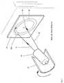
- Fig. 1 Known, og prior art and also uses the local reference numerals substantially.
- An optical transmitting device in the form of a laser beam generator 16 is mounted, for example by a jaw chuck (not shown). This results in practice a different position of the laser beam 12 relative to the spindle axis 30 (shown exaggerated in the drawing).
- Upon rotation of the spindle 29 describes the family of curves of the beams 12 approximately a cone coat , so that on the target 40 a circular ring 32 is described, caused by individual points of light 32 A.
- the annulus is centered around the associated center Z, reference numeral 34, which thus the piercing point of the axis of rotation 30 defined by the target 40.
- a piercing point Z 'can be determined, even if instead of a circular ring there is only one circular arc, or individual points of light 32A, 32B and 32C.
- the corresponding center Z 'can be determined with comparatively great precision by means of best matching and using the least squares method. This succeeds in practice for most contours in direct, non-iterative calculation. If necessary, iterative calculation methods can also be used.
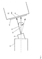
- Fig. 3 This is in Fig. 3 just different.
- a single light beam 12 is emitted with the first spindle locked relative to its axis of rotation 30 and defines a first impact point 42 A on the target 40.
- the position of the axis of rotation 60 of the second spindle 52 relative to the target 40 can now be detected very accurately and check that the second spindle 52 is rotated a few times around an arbitrary angle of rotation (cf., rotation arrow 61), so that, for example, further light points 42B, 42C appear through the light beam 12. They define the circle with the center Z ", where Z" lies on the actual axis of rotation 60 of the spindle.
- Reference number 70 and the symbolically shown plug-in device show that the optical receiving device 40 an electronics or a computer (not shown) is connected downstream, so that the present in electrical form measurement results can be further processed and displayed.
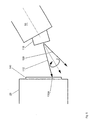
- FIG. 5 the conditions Fig. 3 shown, provided that the transmitting and receiving device 116 or 140 interchanged on the first spindle 29 and 50 are positioned.
- a cone of light rays 112 results about the actual axis of rotation 130, as shown.
- Impact point 132A is thus relatively close to the boundary of the receiving device 140, but can nevertheless serve with further impact points for determining the associated circular center.
- Fig. 4 and 5 determines the determination of the orientation of the spindles relative to each other, as in Fig. 6 shown.
Landscapes
- Physics & Mathematics (AREA)
- General Physics & Mathematics (AREA)
- Length Measuring Devices By Optical Means (AREA)
- Machine Tool Sensing Apparatuses (AREA)
- Automatic Control Of Machine Tools (AREA)
- Turning (AREA)
- A Measuring Device Byusing Mechanical Method (AREA)
- Photometry And Measurement Of Optical Pulse Characteristics (AREA)
Claims (6)
- Procédé de détermination de la position d'axe de deux broches ou arbres de machine l'un par rapport à l'autre, comportant les étapes suivantes :a) sur une première broche de machine ou une première extrémité d'arbre (29), un dispositif d'émission optique (16) est fixé du côté avant, avec lequel un rayon lumineux (12) est émis approximativement dans la direction axiale de la broche (29),b) sur une deuxième broche de machine ou une deuxième extrémité d'arbre (52), qui fait face frontalement à la première broche de machine, respectivement extrémité d'arbre (29), un dispositif de réception optique (40) plat est fixé du côté avant, lequel est conçu afin de recevoir ledit rayon lumineux (12) et de déterminer son point d'incidence selon deux coordonnées,c) la distance entre le dispositif d'émission (16) et le dispositif de réception (40) est déterminée,d) quand la deuxième broche de machine ou la deuxième extrémité d'arbre (52) est fixe, la première broche de machine ou la première extrémité d'arbre (29) est amenée par entraînement manuel ou motorisé dans au moins trois directions de rotation sélectionnable librement, mais définies et les positions correspondantes du point d'incidence (32A,32B,32C) du point lumineux sont enregistrées ; les au moins trois positions enregistrées du point d'incidence sont déduites afin de calculer ou en variante de spécifier le mieux possible au moyen d'une méthode de compensation d'erreurs les paramètres d'un premier cercle (32) correspondant, notamment de son point central (Z') sur le dispositif de réception optique (40),e) quand la première broche de machine ou la première extrémité d'arbre (29) est fixe, la deuxième broche de machine ou la deuxième extrémité d'arbre (52) est amenée par entraînement manuel ou motorisé dans au moins trois positions de rotation sélectionnables librement, mais définies et les positions correspondantes du point d'incidence (42A,42B,42C) du point lumineux sont enregistrées, les au moins trois positions enregistrées du point d'incidence sont déduites afin de calculer ou en variante de spécifier le mieux possible au moyen d'une méthode de compensation d'erreurs les paramètres d'un deuxième cercle correspondant, notamment de son point central (Z") sur le dispositif de réception optique (40),f) le dispositif d'émission (16) et le dispositif de réception (40) sont montés de manière intervertie sur les broches ou arbres de machine (29,52) à contrôler, de telle sorte que le dispositif d'émission optique (16) soit disposé sur la deuxième broche de machine ou la deuxième extrémité d'arbre (52) et le dispositif de réception optique (40) soit disposé sur la première broche de machine ou la première extrémité d'arbre (29),g) les étapes c), d) et e) sont répétées de manière appropriée, de telle sorte que les paramètres d'un troisième et d'un quatrième cercle soient calculés,h) d'après la distance entre le dispositif d'émission (16) et le dispositif de réception (40) ainsi que des paramètres calculés ou spécifiés du deuxième, troisième et quatrième cercle, le déport angulaire ainsi que le déport parallèle des broches ou arbres (29,52) sont calculés dans un plan horizontal et/ou vertical.
- Procédé selon la revendication 1, caractérisé en ce qu'avec les dimensions de déport calculées, se rapportant à un déport parallèle et/ou un déport angulaire, un dispositif est commandé, avec lequel au moins une des deux broches ou un des deux arbres (29,52) est déplacé dans l'espace relativement à l'autre broche respective, de telle sorte qu'un déport restant soit minimisé ou éliminé.
- Procédé selon la revendication 1, caractérisé en ce que les paramètres d'un cercle sont déterminés dans une procédure de calcul directe, non itérative.
- Procédé selon une des revendications précédentes, caractérisé en ce qu'en dehors des paramètres d'un cercle, les paramètres statistiques correspondants du meilleur ajustement de courbe calculé sont indiqués.
- Procédé selon la revendication 1, dans lequel ladite détection de valeur de mesure respective est élargie en ce qu'une détection supplémentaire de position de rotation de la première et/ou deuxième broche (29,52) ou du premier et/ou deuxième arbre est effectuée au moyen d'inclinomètres et les valeurs de mesure d'inclinomètre respectives sont en outre incorporées dans la procédure de calcul afin de déterminer le déport parallèle ou le déport angulaire dans la direction horizontale ou verticale.
- Procédé selon une des revendications précédentes, caractérisé en ce que les points d'incidence observés du rayon lumineux, les cercles calculés correspondants et les dimensions de déport calculées sont affichés sur un écran électronique.
Applications Claiming Priority (2)
| Application Number | Priority Date | Filing Date | Title |
|---|---|---|---|
| DE10109462A DE10109462A1 (de) | 2001-03-01 | 2001-03-01 | Vorrichtung und Verfahren zur Bestimmung der Achslage zweier Maschinenspindeln |
| DE10109462 | 2001-03-01 |
Publications (3)
| Publication Number | Publication Date |
|---|---|
| EP1236971A2 EP1236971A2 (fr) | 2002-09-04 |
| EP1236971A3 EP1236971A3 (fr) | 2003-07-30 |
| EP1236971B1 true EP1236971B1 (fr) | 2009-06-24 |
Family
ID=7675689
Family Applications (1)
| Application Number | Title | Priority Date | Filing Date |
|---|---|---|---|
| EP02001729A Expired - Lifetime EP1236971B1 (fr) | 2001-03-01 | 2002-01-25 | Procédé et dispositif pour la détermination de l'orientation axiale de deux axes de machines |
Country Status (4)
| Country | Link |
|---|---|
| US (1) | US6609305B2 (fr) |
| EP (1) | EP1236971B1 (fr) |
| AT (1) | ATE434751T1 (fr) |
| DE (2) | DE10109462A1 (fr) |
Families Citing this family (18)
| Publication number | Priority date | Publication date | Assignee | Title |
|---|---|---|---|---|
| DE10352719A1 (de) * | 2003-11-12 | 2005-06-23 | Wente, Holger, Dr.-Ing. | Verfahren zur Ausrichtung von zwei Objekten und Laser-Zielplatteneinheit sowie Punktstrahlereinheit hierzu |
| US20050132589A1 (en) * | 2003-12-22 | 2005-06-23 | Johnson Robert F. | Visual alignment aid for handheld tools |
| DE102004020406A1 (de) * | 2004-04-23 | 2005-11-10 | Prüftechnik Dieter Busch AG | Messvorrichtung und Verfahren zum Ermitteln der Geradheit hohlzylindrischer oder hohlkegeliger Körper bzw. deren Orientierung relativ zueinander |
| ATE420337T1 (de) | 2005-03-04 | 2009-01-15 | Busch Dieter & Co Prueftech | Verfahren zum ausrichten von maschinen oder maschinenteilen |
| DE502006004670D1 (de) * | 2005-04-20 | 2009-10-08 | Busch Dieter & Co Prueftech | Enatmung an kurbelwellen |
| US20090268214A1 (en) * | 2006-05-26 | 2009-10-29 | Miljenko Lucic | Photogrammetric system and techniques for 3d acquisition |
| DE102008010916A1 (de) * | 2008-02-25 | 2009-08-27 | Prüftechnik Dieter Busch AG | Verfahren und Vorrichtung zur Ermittlung einer Ausrichtung von zwei drehbar gelagerten Maschinenteilen, einer Ausrichtung von zwei hohlzylinderförmigen Maschinenteilen oder zur Prüfung einer Komponente auf Geradheit entlang einer Längsseite |
| DE102011004434A1 (de) | 2011-02-21 | 2012-08-23 | Schaeffler Technologies Gmbh & Co. Kg | Laser-Ausrichtsystem zur Messung einer Ausrichtung rotierender Maschinenteile sowie Verfahren zur Aufbereitung von Messergebnissen eines Laser-Ausrichtungssystems |
| CN102944698B (zh) * | 2012-11-29 | 2014-06-25 | 西安工业大学 | 天幕靶光幕参数检定装置及检定方法 |
| JP6004954B2 (ja) * | 2013-01-18 | 2016-10-12 | 三菱重工業株式会社 | 法線検出装置、加工装置、及び法線検出方法 |
| DE102014210248A1 (de) * | 2014-05-28 | 2015-12-03 | Prüftechnik Dieter Busch AG | Verfahren zum Ermitteln einer geschlossenen Bahnkurve mittels eines Lasers und eines Laserlichtsensors und Vorrichtung zum Ermitteln einer geschlossenen Bahnkurve |
| DE102014210244A1 (de) * | 2014-05-28 | 2015-12-03 | Prüftechnik Dieter Busch AG | Verfahren zum Ermitteln einer geschlossenen Bahnkurve mittels eines Lasers und einem Laserlicht-Sensor und Vorrichtung zum Ermitteln einer geschlossenen Bahnkurve |
| DE102014212797A1 (de) | 2014-07-02 | 2016-01-07 | Prüftechnik Dieter Busch AG | Verfahren zum Ermitteln der Ausrichtung eines Laserlichtstrahls in Bezug auf eine Drehachse einer Einrichtung, die um die Drehachse rotierbar ist, und Laserlicht-Erfassungseinrichtung |
| CZ2014855A3 (cs) * | 2014-12-04 | 2015-11-25 | VĂšTS, a.s. | Způsob stanovení nebo stanovování lineární a/nebo úhlové úchylky/úchylek dráhy nebo plochy obrobku nebo části stroje od osy rotace jeho vřetena, a snímací zařízení k jeho provádění |
| CN108444346B (zh) * | 2018-02-23 | 2023-12-08 | 中国科学院西安光学精密机械研究所 | 回转体中心线引出装置及方法 |
| DE102018112436A1 (de) * | 2018-05-24 | 2019-11-28 | Carl Zeiss Jena Gmbh | Verfahren und Vorrichtungen zur Bestimmung von Ausrichtungsfehlern von Strahlquellen und für deren Korrektur |
| CN110243312B (zh) * | 2019-05-09 | 2024-06-18 | 上海联影医疗科技股份有限公司 | 机架同轴度测量系统、装置、方法及存储介质 |
| CN115824096B (zh) * | 2022-12-05 | 2026-03-20 | 上海船舶工艺研究所(中国船舶集团有限公司第十一研究所) | 用激光跟踪仪测量舱壁阻隔柴发机组轴对中的方法及装置 |
Family Cites Families (12)
| Publication number | Priority date | Publication date | Assignee | Title |
|---|---|---|---|---|
| US4102052A (en) * | 1976-12-14 | 1978-07-25 | Exxon Research & Engineering Co. | Deflection indicator for couplings |
| FR2517068B1 (fr) * | 1981-11-24 | 1985-10-11 | Inst Francais Du Petrole | Methode et dispositif pour mettre dans une position relative determinee deux elements immerges dans un milieu liquide conducteur |
| US4566202A (en) * | 1983-12-06 | 1986-01-28 | Hamar M R | Laser apparatus for effectively projecting the axis of rotation of a rotating tool holder |
| US4709485A (en) * | 1986-12-04 | 1987-12-01 | Mobil Oil Corporation | Shaft alignment method and apparatus |
| US4928401A (en) * | 1989-01-03 | 1990-05-29 | Murray Jr Malcolm G | Shaft alignment system |
| DE3911307C2 (de) * | 1989-04-07 | 1998-04-09 | Busch Dieter & Co Prueftech | Verfahren zum Feststellen, ob zwei hintereinander angeordnete Wellen hinsichtlich ihrer Mittelachse fluchten oder versetzt sind |
| US5224052A (en) | 1989-10-26 | 1993-06-29 | Hamar M R | Laser alignment control system |
| US5077905A (en) * | 1990-06-04 | 1992-01-07 | Murray Jr Malcolm G | Laser alignment mount assembly and method |
| US5148232A (en) * | 1991-01-28 | 1992-09-15 | Intra Corporation | Laser apparatus and method for aligning a crankpin grinding machine |
| US5435073A (en) * | 1993-04-05 | 1995-07-25 | Texaco Inc. | Alignment tool for rotating equipment |
| EP0853752B1 (fr) * | 1996-08-07 | 2002-10-23 | Prüftechnik Dieter Busch Ag | Dispositif pour determiner des defauts d'alignement de deux arbres disposes l'un derriere l'autre |
| US6427348B1 (en) * | 2000-07-17 | 2002-08-06 | James Webb | Slope block |
-
2001
- 2001-03-01 DE DE10109462A patent/DE10109462A1/de not_active Withdrawn
-
2002
- 2002-01-25 EP EP02001729A patent/EP1236971B1/fr not_active Expired - Lifetime
- 2002-01-25 DE DE50213627T patent/DE50213627D1/de not_active Expired - Lifetime
- 2002-01-25 AT AT02001729T patent/ATE434751T1/de not_active IP Right Cessation
- 2002-03-01 US US10/085,624 patent/US6609305B2/en not_active Expired - Lifetime
Also Published As
| Publication number | Publication date |
|---|---|
| ATE434751T1 (de) | 2009-07-15 |
| US20020129504A1 (en) | 2002-09-19 |
| US6609305B2 (en) | 2003-08-26 |
| EP1236971A3 (fr) | 2003-07-30 |
| EP1236971A2 (fr) | 2002-09-04 |
| DE10109462A1 (de) | 2002-09-05 |
| DE50213627D1 (de) | 2009-08-06 |
Similar Documents
| Publication | Publication Date | Title |
|---|---|---|
| EP1236971B1 (fr) | Procédé et dispositif pour la détermination de l'orientation axiale de deux axes de machines | |
| DE3911307C2 (de) | Verfahren zum Feststellen, ob zwei hintereinander angeordnete Wellen hinsichtlich ihrer Mittelachse fluchten oder versetzt sind | |
| EP1342051B1 (fr) | Calibrage d'un capteur de mesure d'un appareil de mesure de coordonnees au moyen d'une boule, dont le centre est connu | |
| EP2093537B1 (fr) | Système et procédé pour déterminer l'alignement de deux pièces de machine rotatives | |
| DE69215287T2 (de) | Sensor zum Erfassen der Drehlage für Laserausrichtungsteuerungsysteme | |
| EP3384236B1 (fr) | Procédé de contrôle et/ou d'étalonnage d'un axe vertical d'un laser rotatif | |
| DE2213963C3 (de) | Werkstatt-Meßgerät | |
| EP2950043B1 (fr) | Procédé de détermination d'une trajectoire sur une trajectoire fermée à l'aide d'un laser et d'un capteur à lumière laser et dispositif de détermination d'une trajectoire fermée | |
| WO2014114737A2 (fr) | Procédé et dispositif de détermination de la géométrie de structures au moyen de la tomographie assistée par ordinateur | |
| EP1528353A1 (fr) | Procédé pour calibrer un système de mesure en trois dimensions | |
| EP1678468A1 (fr) | Procede pour verifier ou etalonner l'alignement dependant de sa position angulaire d'une eprouvette de haute precision | |
| WO2007124902A2 (fr) | Dispositif et procédé permettant d'évaluer la position relative dans l'espace de deux objets | |
| DE19733919A1 (de) | Vorrichtung und Verfahren zum gegenseitigen Ausrichten von Wellen | |
| DE10048096A1 (de) | Verfahren zur Kalibrierung eines messenden Sensors auf einem Koordinatenmeßgerät | |
| EP0564535B1 (fr) | Determination de la position relative de points de mesure | |
| EP2455710A2 (fr) | Appareil à laser rotatif et procédé de commande d'un rayon laser | |
| EP0928951B1 (fr) | Capteur de mesure de position pour l'alignement mutuel des objets | |
| EP0734305B1 (fr) | Procede pour le reglage d'alesoirs et outils analogues | |
| EP0771406B1 (fr) | Dispositif et procede de mesure et de calcul de parametres geometriques d'un corps | |
| DE102006023926A1 (de) | Vorrichtung und Verfahren zur quantitativen Beurteilung der räumlichen Lage zweier Maschinenteile, Wellen, Spindeln, Werkstücke oder anderer Gegenstände relativ zueinander | |
| EP1854506A1 (fr) | Vérification de la précision du positionnement d'une table pour patient en référence à un isocentre | |
| DE102006011814A1 (de) | Werkzeugmessgerät zur Vermessung eines Werkzeugs in einem Werkzeughalter und Werkzeughalter | |
| DE102017107245A1 (de) | Vorrichtung und Verfahren zur Vermessung von Hohlräumen sowie Verwendung der Vorrichtung zur Bestimmung von Walzenausrichtungen | |
| EP1126235B1 (fr) | Méthode et dispositif pour déterminer l'orientation d'un corps tournant sur palier relative à une direction de référence | |
| EP1473540B1 (fr) | Procédé et dispositif pour déterminer le niveau de plusieurs points de mesure |
Legal Events
| Date | Code | Title | Description |
|---|---|---|---|
| PUAI | Public reference made under article 153(3) epc to a published international application that has entered the european phase |
Free format text: ORIGINAL CODE: 0009012 |
|
| AK | Designated contracting states |
Kind code of ref document: A2 Designated state(s): AT BE CH CY DE DK ES FI FR GB GR IE IT LI LU MC NL PT SE TR |
|
| AX | Request for extension of the european patent |
Free format text: AL;LT;LV;MK;RO;SI |
|
| PUAL | Search report despatched |
Free format text: ORIGINAL CODE: 0009013 |
|
| AK | Designated contracting states |
Designated state(s): AT BE CH CY DE DK ES FI FR GB GR IE IT LI LU MC NL PT SE TR |
|
| AX | Request for extension of the european patent |
Extension state: AL LT LV MK RO SI |
|
| 17P | Request for examination filed |
Effective date: 20040112 |
|
| AKX | Designation fees paid |
Designated state(s): AT BE CH CY DE DK ES FI FR GB GR IE IT LI LU MC NL PT SE TR |
|
| 17Q | First examination report despatched |
Effective date: 20050822 |
|
| GRAP | Despatch of communication of intention to grant a patent |
Free format text: ORIGINAL CODE: EPIDOSNIGR1 |
|
| GRAS | Grant fee paid |
Free format text: ORIGINAL CODE: EPIDOSNIGR3 |
|
| GRAA | (expected) grant |
Free format text: ORIGINAL CODE: 0009210 |
|
| AK | Designated contracting states |
Kind code of ref document: B1 Designated state(s): AT BE CH CY DE DK ES FI FR GB GR IE IT LI LU MC NL PT SE TR |
|
| REG | Reference to a national code |
Ref country code: GB Ref legal event code: FG4D Free format text: NOT ENGLISH |
|
| REG | Reference to a national code |
Ref country code: CH Ref legal event code: EP |
|
| REG | Reference to a national code |
Ref country code: IE Ref legal event code: FG4D Free format text: LANGUAGE OF EP DOCUMENT: GERMAN |
|
| REF | Corresponds to: |
Ref document number: 50213627 Country of ref document: DE Date of ref document: 20090806 Kind code of ref document: P |
|
| REG | Reference to a national code |
Ref country code: SE Ref legal event code: TRGR |
|
| PG25 | Lapsed in a contracting state [announced via postgrant information from national office to epo] |
Ref country code: FI Free format text: LAPSE BECAUSE OF FAILURE TO SUBMIT A TRANSLATION OF THE DESCRIPTION OR TO PAY THE FEE WITHIN THE PRESCRIBED TIME-LIMIT Effective date: 20090624 |
|
| NLV1 | Nl: lapsed or annulled due to failure to fulfill the requirements of art. 29p and 29m of the patents act | ||
| PG25 | Lapsed in a contracting state [announced via postgrant information from national office to epo] |
Ref country code: ES Free format text: LAPSE BECAUSE OF FAILURE TO SUBMIT A TRANSLATION OF THE DESCRIPTION OR TO PAY THE FEE WITHIN THE PRESCRIBED TIME-LIMIT Effective date: 20091005 |
|
| REG | Reference to a national code |
Ref country code: IE Ref legal event code: FD4D |
|
| PG25 | Lapsed in a contracting state [announced via postgrant information from national office to epo] |
Ref country code: NL Free format text: LAPSE BECAUSE OF FAILURE TO SUBMIT A TRANSLATION OF THE DESCRIPTION OR TO PAY THE FEE WITHIN THE PRESCRIBED TIME-LIMIT Effective date: 20090624 |
|
| PG25 | Lapsed in a contracting state [announced via postgrant information from national office to epo] |
Ref country code: PT Free format text: LAPSE BECAUSE OF FAILURE TO SUBMIT A TRANSLATION OF THE DESCRIPTION OR TO PAY THE FEE WITHIN THE PRESCRIBED TIME-LIMIT Effective date: 20091024 |
|
| PG25 | Lapsed in a contracting state [announced via postgrant information from national office to epo] |
Ref country code: IE Free format text: LAPSE BECAUSE OF FAILURE TO SUBMIT A TRANSLATION OF THE DESCRIPTION OR TO PAY THE FEE WITHIN THE PRESCRIBED TIME-LIMIT Effective date: 20090624 Ref country code: DK Free format text: LAPSE BECAUSE OF FAILURE TO SUBMIT A TRANSLATION OF THE DESCRIPTION OR TO PAY THE FEE WITHIN THE PRESCRIBED TIME-LIMIT Effective date: 20090624 |
|
| PLBE | No opposition filed within time limit |
Free format text: ORIGINAL CODE: 0009261 |
|
| STAA | Information on the status of an ep patent application or granted ep patent |
Free format text: STATUS: NO OPPOSITION FILED WITHIN TIME LIMIT |
|
| 26N | No opposition filed |
Effective date: 20100325 |
|
| BERE | Be: lapsed |
Owner name: PRUFTECHNIK DIETER BUSCH A.G. Effective date: 20100131 |
|
| PG25 | Lapsed in a contracting state [announced via postgrant information from national office to epo] |
Ref country code: MC Free format text: LAPSE BECAUSE OF NON-PAYMENT OF DUE FEES Effective date: 20100131 |
|
| REG | Reference to a national code |
Ref country code: CH Ref legal event code: PL |
|
| PG25 | Lapsed in a contracting state [announced via postgrant information from national office to epo] |
Ref country code: GR Free format text: LAPSE BECAUSE OF FAILURE TO SUBMIT A TRANSLATION OF THE DESCRIPTION OR TO PAY THE FEE WITHIN THE PRESCRIBED TIME-LIMIT Effective date: 20090925 Ref country code: LI Free format text: LAPSE BECAUSE OF NON-PAYMENT OF DUE FEES Effective date: 20100131 Ref country code: CH Free format text: LAPSE BECAUSE OF NON-PAYMENT OF DUE FEES Effective date: 20100131 |
|
| PG25 | Lapsed in a contracting state [announced via postgrant information from national office to epo] |
Ref country code: BE Free format text: LAPSE BECAUSE OF NON-PAYMENT OF DUE FEES Effective date: 20100131 |
|
| PG25 | Lapsed in a contracting state [announced via postgrant information from national office to epo] |
Ref country code: IT Free format text: LAPSE BECAUSE OF FAILURE TO SUBMIT A TRANSLATION OF THE DESCRIPTION OR TO PAY THE FEE WITHIN THE PRESCRIBED TIME-LIMIT Effective date: 20090624 |
|
| PG25 | Lapsed in a contracting state [announced via postgrant information from national office to epo] |
Ref country code: AT Free format text: LAPSE BECAUSE OF NON-PAYMENT OF DUE FEES Effective date: 20100125 |
|
| PG25 | Lapsed in a contracting state [announced via postgrant information from national office to epo] |
Ref country code: CY Free format text: LAPSE BECAUSE OF FAILURE TO SUBMIT A TRANSLATION OF THE DESCRIPTION OR TO PAY THE FEE WITHIN THE PRESCRIBED TIME-LIMIT Effective date: 20090624 |
|
| PG25 | Lapsed in a contracting state [announced via postgrant information from national office to epo] |
Ref country code: LU Free format text: LAPSE BECAUSE OF NON-PAYMENT OF DUE FEES Effective date: 20100125 |
|
| PG25 | Lapsed in a contracting state [announced via postgrant information from national office to epo] |
Ref country code: TR Free format text: LAPSE BECAUSE OF FAILURE TO SUBMIT A TRANSLATION OF THE DESCRIPTION OR TO PAY THE FEE WITHIN THE PRESCRIBED TIME-LIMIT Effective date: 20090624 |
|
| REG | Reference to a national code |
Ref country code: FR Ref legal event code: PLFP Year of fee payment: 15 |
|
| REG | Reference to a national code |
Ref country code: FR Ref legal event code: PLFP Year of fee payment: 16 |
|
| REG | Reference to a national code |
Ref country code: FR Ref legal event code: PLFP Year of fee payment: 17 |
|
| PGFP | Annual fee paid to national office [announced via postgrant information from national office to epo] |
Ref country code: DE Payment date: 20190124 Year of fee payment: 18 Ref country code: FR Payment date: 20190122 Year of fee payment: 18 Ref country code: GB Payment date: 20190124 Year of fee payment: 18 |
|
| PGFP | Annual fee paid to national office [announced via postgrant information from national office to epo] |
Ref country code: SE Payment date: 20190124 Year of fee payment: 18 |
|
| REG | Reference to a national code |
Ref country code: DE Ref legal event code: R119 Ref document number: 50213627 Country of ref document: DE |
|
| REG | Reference to a national code |
Ref country code: SE Ref legal event code: EUG |
|
| GBPC | Gb: european patent ceased through non-payment of renewal fee |
Effective date: 20200125 |
|
| REG | Reference to a national code |
Ref country code: SE Ref legal event code: EUG |
|
| PG25 | Lapsed in a contracting state [announced via postgrant information from national office to epo] |
Ref country code: FR Free format text: LAPSE BECAUSE OF NON-PAYMENT OF DUE FEES Effective date: 20200131 Ref country code: DE Free format text: LAPSE BECAUSE OF NON-PAYMENT OF DUE FEES Effective date: 20200801 Ref country code: SE Free format text: LAPSE BECAUSE OF NON-PAYMENT OF DUE FEES Effective date: 20200126 Ref country code: GB Free format text: LAPSE BECAUSE OF NON-PAYMENT OF DUE FEES Effective date: 20200125 |