EP1237033A2 - Mélangeur pour l'intégration de lumière en forme de bâton creux et procédé pour sa fabrication - Google Patents
Mélangeur pour l'intégration de lumière en forme de bâton creux et procédé pour sa fabrication Download PDFInfo
- Publication number
- EP1237033A2 EP1237033A2 EP01130317A EP01130317A EP1237033A2 EP 1237033 A2 EP1237033 A2 EP 1237033A2 EP 01130317 A EP01130317 A EP 01130317A EP 01130317 A EP01130317 A EP 01130317A EP 1237033 A2 EP1237033 A2 EP 1237033A2
- Authority
- EP
- European Patent Office
- Prior art keywords
- section
- cross
- side parts
- face
- mixing rod
- Prior art date
- Legal status (The legal status is an assumption and is not a legal conclusion. Google has not performed a legal analysis and makes no representation as to the accuracy of the status listed.)
- Withdrawn
Links
- 238000002156 mixing Methods 0.000 title claims abstract description 52
- 238000004519 manufacturing process Methods 0.000 title claims abstract description 24
- 238000010438 heat treatment Methods 0.000 claims description 2
- 239000011521 glass Substances 0.000 description 8
- 238000000227 grinding Methods 0.000 description 8
- 239000010410 layer Substances 0.000 description 8
- 238000003384 imaging method Methods 0.000 description 7
- 230000003287 optical effect Effects 0.000 description 7
- BQCADISMDOOEFD-UHFFFAOYSA-N Silver Chemical compound [Ag] BQCADISMDOOEFD-UHFFFAOYSA-N 0.000 description 3
- 239000000463 material Substances 0.000 description 3
- 229910052709 silver Inorganic materials 0.000 description 3
- 239000004332 silver Substances 0.000 description 3
- LYKJEJVAXSGWAJ-UHFFFAOYSA-N compactone Natural products CC1(C)CCCC2(C)C1CC(=O)C3(O)CC(C)(CCC23)C=C LYKJEJVAXSGWAJ-UHFFFAOYSA-N 0.000 description 2
- 238000001816 cooling Methods 0.000 description 2
- 239000011159 matrix material Substances 0.000 description 2
- 229910052751 metal Inorganic materials 0.000 description 2
- 239000002184 metal Substances 0.000 description 2
- 229910001092 metal group alloy Inorganic materials 0.000 description 2
- 238000000034 method Methods 0.000 description 2
- 238000003801 milling Methods 0.000 description 2
- 239000004033 plastic Substances 0.000 description 2
- 238000005266 casting Methods 0.000 description 1
- 239000000919 ceramic Substances 0.000 description 1
- 238000009826 distribution Methods 0.000 description 1
- 230000003760 hair shine Effects 0.000 description 1
- 238000001746 injection moulding Methods 0.000 description 1
- 238000005498 polishing Methods 0.000 description 1
- 238000003825 pressing Methods 0.000 description 1
- 239000011241 protective layer Substances 0.000 description 1
- 239000007787 solid Substances 0.000 description 1
Images


Classifications
-
- G—PHYSICS
- G02—OPTICS
- G02B—OPTICAL ELEMENTS, SYSTEMS OR APPARATUS
- G02B27/00—Optical systems or apparatus not provided for by any of the groups G02B1/00 - G02B26/00, G02B30/00
- G02B27/09—Beam shaping, e.g. changing the cross-sectional area, not otherwise provided for
- G02B27/0938—Using specific optical elements
- G02B27/0994—Fibers, light pipes
-
- G—PHYSICS
- G02—OPTICS
- G02B—OPTICAL ELEMENTS, SYSTEMS OR APPARATUS
- G02B27/00—Optical systems or apparatus not provided for by any of the groups G02B1/00 - G02B26/00, G02B30/00
- G02B27/09—Beam shaping, e.g. changing the cross-sectional area, not otherwise provided for
-
- G—PHYSICS
- G02—OPTICS
- G02B—OPTICAL ELEMENTS, SYSTEMS OR APPARATUS
- G02B6/00—Light guides; Structural details of arrangements comprising light guides and other optical elements, e.g. couplings
- G02B6/24—Coupling light guides
- G02B6/26—Optical coupling means
- G02B6/28—Optical coupling means having data bus means, i.e. plural waveguides interconnected and providing an inherently bidirectional system by mixing and splitting signals
- G02B6/2804—Optical coupling means having data bus means, i.e. plural waveguides interconnected and providing an inherently bidirectional system by mixing and splitting signals forming multipart couplers without wavelength selective elements, e.g. "T" couplers, star couplers
- G02B6/2808—Optical coupling means having data bus means, i.e. plural waveguides interconnected and providing an inherently bidirectional system by mixing and splitting signals forming multipart couplers without wavelength selective elements, e.g. "T" couplers, star couplers using a mixing element which evenly distributes an input signal over a number of outputs
Definitions
- the invention relates to a manufacturing method for a hollow mixing rod and to one Hollow mixing rod with four side parts, each with a reflective inside, one side each a cavity extending from a light entry surface to a light exit surface forms a square cross section.
- a manufacturing method for a hollow mixing rod To provide with the hollow mixing rod can be easily and accurately manufactured, even if two cross-sectional sides of the cavity converge at an angle that is not equal to 90 °. Furthermore, a hollow mixing rod of the type mentioned should be improved so that it is as easy to manufacture as possible.
- this object is achieved by the production method for a hollow mixing rod has a cavity with a square cross section, solved with the following steps: manufacture one first and a second side part, each of a T-shaped cross section with a crossbar and has a central web projecting therefrom, which has a central web facing away from the transverse web, reflective end face and seen in cross section a first and a second from the end face includes the side surface extending to the crosspiece, the end surface at least in the first side part and the first side surface seen in cross section converge at an angle that is not equal 90 °, manufacture a third and fourth side part, each with a reflective, flat Inside, assembling the four side panels so that the end face of the first and second Side part facing each other and that the reflective insides of the third and fourth Side part seen in cross section run parallel to each other and with their edge sections rest on the side surfaces of the crossbars, so that the cavity to form the square Cross-section is limited.
- the ground and optionally polished end surface can still be mirrored. You can do this, for example, by mirroring with a silver layer or by applying a dielectric reflecting layer. ever Depending on the type of mirror layer, a protective layer can optionally be applied to the mirror layer be applied.
- the end surface can also be formed by milling instead of grinding, preferably the End surface is still polished.
- the side parts can be made of glass, metal, metal alloys, ceramic or plastic. If plastic is used, the first and second side part can be made, for example, by Injection molding can be formed with the tapered end surface.
- the end face may be preferred still be reworked if the flatness of the end surface is to be improved. Here too the end face will be mirrored. If metal or a metal alloy is used, the reflective property of the end surface can only be produced by polishing. Even with these Materials can already have the side parts with beveled end surfaces such. B. by casting process be formed. Alternatively, of course, is also grinding or milling to chamfer the End surface possible.
- a heat shrink tube pulled over the four side parts the is then heated. Due to the heating, the hose shrinks or contracts and thereby pushes the four side parts against each other. Because the shrink tube is his retracted shape after cooling, permanent fixation of the Side parts reached.
- the shrink tube can be in the middle area of the hollow mixing rod Seen in the longitudinal direction. Alternatively, two shrink sleeves can be attached the end portions of the hollow mixing rod can be provided seen in the longitudinal direction.
- the Using the shrink tube leads to a very simple and effective way of fixing of the four side parts relative to one another, which can be carried out easily and without problems. In particular pressing the four side parts against one another by means of the shrink tube leads to the fact that no gaps between the mirrored or reflective insides occur, so that the Hollow mixing rod can be manufactured with the required high accuracy in a simple manner can.
- the hollow mixing rod according to the invention with the four side parts, each with a flat, reflective. Inside, one side each from a light entry surface to one This forms the light exit surface extending cavity with a square cross section characterized in that the first and second side part each have a T-shaped cross section with a Crossbar and a projecting central web, the opposite of the crossbar End surface forms the reflective inside of the side part and seen in cross section a first and a second side surface extending from the end surface to the crossbar, the reflective inner sides of the third and fourth side part seen in cross section to each other are arranged in parallel and with their edge sections on the side surfaces of the crossbars rest, at least in the first side part, the end surface and the first side surface in Seen cross section converge at an angle that is not equal to 90 °.
- the hollow mixing rod according to the invention is thus particularly easy to produce, since it forms a Cross-sectional shape of the cavity, with two sides at an angle in a corner converge, which is not equal to 90 °, z. B. only the end face of the first side part obliquely must be ground down. This is easy and simple with the required high accuracy possible.
- the first side part thus preferably has an obliquely ground end surface.
- the end face of the center bar therefore defines the angle at which the two cross-sectional sides converge and which is not 90 °, solid.
- the inside of the third and fourth Side part with its edge sections on the side surfaces of the central webs, so that the Center bars of the first and second side panels also serve to distance the specify and maintain reflective inner surfaces of the third and fourth side part.
- the four Side parts held together by a shrink tube In an advantageous development of the hollow mixing rod according to the invention, the four Side parts held together by a shrink tube.
- the use of a Shrink tube to hold together and fix the four side parts leads to one Simplified manufacture of the hollow mixing rod because the shrink tube only over the four side parts put on and then warmed up.
- the fixation and alignment of the four side parts is then done almost automatically, because the contracting shrink tube attaches to the outer shape who adjusts the four side parts and presses them against each other.
- With the Shrink tubing is also prevented from the hollow mixing rod between the reflective Has insides so that the reflective surfaces lie light-tight against each other.
- the end face and the first side surface seen in cross section also converge at an angle that is not equal to 90 °.
- the third and fourth side parts in each case have an I-shaped cross section, the third and fourth side part with its long sides abuts the crossbars of the first and second side part. This makes it a very compact one Hollow mixing rod realized, which is stable.
- the hollow mixing rod according to the invention can be produced in particular in an optical device and projecting an image.
- the optical device preferably contains one Light source, an imaging element and a projection optics, the hollow mixing rod is interposed between the light source and the imaging element.
- the light from the light source is coupled into the hollow mixing rod via the light entry surface and in the hollow mixing rod up to Led light exit surface. In doing so, the light rays are reflected on the reflective inner sides meet, led through one or more reflections to the light exit surface. This leads to the luminance distribution in the light exit area compared to that in the light entry area is more uniform, so that a field that shines as uniformly as possible in the light exit surface is produced.
- This luminous field is interposed, for example, with an intermediate optic mapped onto the imaging element in order to illuminate it as evenly as possible.
- the imaging element is controlled on the basis of predetermined image data by means of a control unit, to generate the image that is projected onto a projection surface using the projection optics.
- the hollow mixing rod 1 comprises four side parts 2, 3, 4 and 5, which have a cavity 6 Form trapezoidal cross-section, both seen in the longitudinal direction of the hollow mixing rod 1 Ends are open and a trapezoidal light entry surface 7 and a trapezoidal Form light exit surface 8.
- the hollow mixing rod 1 is in one with respect to one Cross-sectional plane lying central axis A formed symmetrically, so that the first and second side part 2, 3 and the third and fourth side part 4, 5 have the same structure. in the the following only describes the structure of the second and third side parts 3, 4 in detail.
- the second side part 3 has a T-shaped cross section with a cross piece 9 and one of them project in the middle of the center bar 10.
- the central web 10 extends perpendicular to the transverse web 9, so that the side surfaces 11, 12 of the central web 10 perpendicular to the base surfaces 13, 14 of the cross web 9 run.
- the flat end face 15 of the central web 10 facing away from the transverse web 9 connects the two side surfaces 11, 12 with each other and runs with the side surface 11 at an angle ⁇ together that is less than 90 °. In the exemplary embodiment shown here, the angle is 83 °.
- the end surface 15, which delimits one side of the cavity 6, is designed to be reflective. With this one Embodiment described, the second side part 3 is made of glass and the end surface 15 is with a mirror layer made of silver, for example, or with a dielectric mirror layer Mistake.
- the third side part 4 has an I-shaped cross section with a reflective inner side 16.
- the third side part 4 is also made of glass and the reflective inside 16 is again mirrored, for example with a silver layer or a dielectric mirror layer.
- the shape of the third side part 4 is chosen so that its long sides 17, 18 perpendicular to the reflective Run inside 16.
- the first and second side parts 2, 3 are arranged at a predetermined distance from one another, with the two end faces 15 facing each other and forming the right and left side parts of the hollow mixing rod 1.
- the upper and lower side part of the hollow mixing rod 1 is by the third and fourth side part 4, 5 realized, the third side part 4 with its two side Edge areas rests on the side surfaces 11 of the central webs 10 and the fourth side part 5 with its two lateral edge areas rests on the side surfaces 12 of the central webs 10, so that the reflective inner sides 16 of the third and fourth side parts 4, 5 seen in cross section run parallel to each other.
- the four side parts 2 to 5 are made by a hollow mixing rod 1 put on shrink tube 19 (which is only shown in Fig. 1) pressed against each other and fixed.
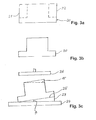
- the T-shaped side part 2, 3 is made from a glass blank 20 with an I-shaped one Cross section (Fig. 3a) made, the length of which corresponds to the length of the hollow mixing rod 1 is selected.
- the side regions 21, 22 are removed from this glass blank 20 (for example by grinding) so that the T-shaped cross section shown in Fig. 3b is formed.
- the angle ⁇ is chosen so that it corresponds to the angle 90 ° - ⁇ .
- the angle ⁇ is thus 7 °.
- the crossbar of the T-shaped glass blank 20 facing away from the end surface of the central web 10 is then by means of a grinding wheel 26 ground until the end face 15 (shown as a broken line in Fig. 3c) with the desired Inclination towards the side surfaces of the central web is formed.
- This end surface 15 is then still polished and mirrored. In this way, any desired angle of inclination can be very easily End surface 15 are formed relative to the side surfaces 11, 12 of the central web 10. That’s it first and second side parts 2, 3 completed.
- the carrier plate 24 and the wedge 23 can also be a Be a tool.
- the third and fourth side part 4, 5 is also formed from an I-shaped blank, the latter being Inside, which, in the assembled state of the hollow mixing rod 1, delimits the cavity 6, is polished and mirrored.
- the four side parts 2 to 5 thus formed are then in accordance with the structure shown in FIGS. 1 and 2 composed.
- the shrink tube 19 is slipped over, the inside cross section is larger than the outer cross section of the hollow mixing rod 1, so that it is easy to slip on.
- the shrink tube 19 is heated so that it contracts and thereby the four Side parts 2 to 5 press against each other and fixed.
- the shrink tube 19 keeps this contracted shape even after cooling, so that the side parts 2 to 5 permanently are pressed against each other and are thus permanently fixed.
- This optical device comprises a light source 27 and the hollow mixing rod 1 connected downstream thereof, in the one facing the light source 27 Light entry surface 7 light from the light source 1 is coupled, which is then in the hollow mixing rod 1 to Light exit surface 8 is directed.
- the optical device further contains one of the light exit surface 8 of the hollow mixing rod 1 downstream intermediate optics 28, with which the from the light exit surface 8th emerging light is directed onto an imaging element 29 so that it is as possible is evenly illuminated.
- An imaging element 29 can be, for example Tilting mirror matrix or an LCD matrix can be used.
- the imaging element 29 is by means of a control unit (not shown) driven on the basis of predetermined image data, so that the desired image can be set, which is then by means of projection optics 30 Optical device is projected on a projection surface 31.
- FIG. 5 A further embodiment of the hollow mixing rod 1 can be seen in FIG. 5.
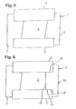
- This embodiment differs from the embodiment shown in Fig. 2 in that the first side part 2 so Is rotated 180 ° that the cavity 6 has a parallelogram cross section.
- the first and second side parts 2, 3 have the same cross-sectional shape, so that advantageously only one Kind of T-shaped side parts with an inclined end face 15 must be produced.
- the first and second side parts 2, 3, the inclination of the end face 15 is different great to choose. In this case, two different types of side parts have to be produced become.
- FIG. 6 A further embodiment is shown in FIG. 6, in which compared to that in FIGS. 1 and 2 shown embodiment, a T-shaped side part 32 is provided instead of the first side part 2, the end surface 33 of the central web 34 perpendicular to the side surfaces 35, 36 of the central web 34 runs.
Landscapes
- Physics & Mathematics (AREA)
- General Physics & Mathematics (AREA)
- Optics & Photonics (AREA)
- Optical Elements Other Than Lenses (AREA)
- Extrusion Of Metal (AREA)
- Exhaust Gas After Treatment (AREA)
- Extrusion Moulding Of Plastics Or The Like (AREA)
Applications Claiming Priority (2)
| Application Number | Priority Date | Filing Date | Title |
|---|---|---|---|
| DE10109591A DE10109591A1 (de) | 2001-02-28 | 2001-02-28 | Herstellungsverfahren für einen Hohlmischstab und Hohlmischstab |
| DE10109591 | 2001-02-28 |
Publications (2)
| Publication Number | Publication Date |
|---|---|
| EP1237033A2 true EP1237033A2 (fr) | 2002-09-04 |
| EP1237033A3 EP1237033A3 (fr) | 2003-09-17 |
Family
ID=7675773
Family Applications (1)
| Application Number | Title | Priority Date | Filing Date |
|---|---|---|---|
| EP01130317A Withdrawn EP1237033A3 (fr) | 2001-02-28 | 2001-12-19 | Mélangeur pour l'intégration de lumière en forme de bâton creux et procédé pour sa fabrication |
Country Status (3)
| Country | Link |
|---|---|
| US (1) | US6625380B2 (fr) |
| EP (1) | EP1237033A3 (fr) |
| DE (1) | DE10109591A1 (fr) |
Families Citing this family (18)
| Publication number | Priority date | Publication date | Assignee | Title |
|---|---|---|---|---|
| TW523120U (en) * | 2002-06-26 | 2003-03-01 | Young Optics Inc | Assembling structure of hollow integration post |
| JP4018949B2 (ja) * | 2002-07-29 | 2007-12-05 | フジノン株式会社 | ロッドインテグレータの製造方法 |
| US7169252B2 (en) * | 2003-07-11 | 2007-01-30 | Oc Oerlikon Balzers Ag | Method for the assembly of light integrators |
| US20050135761A1 (en) * | 2003-12-23 | 2005-06-23 | Cannon Bruce L. | Optical element for uniform illumination and optical system incorporating same |
| TW200532351A (en) * | 2004-03-29 | 2005-10-01 | Coretronic Corp | Mounting structure for hollow integration rod |
| US20050244126A1 (en) * | 2004-04-30 | 2005-11-03 | Hewlett-Packard Co. | Light guides and method of forming same |
| TWI264608B (en) * | 2005-04-08 | 2006-10-21 | Delta Electronics Inc | Light tunnel module |
| TWI312905B (en) * | 2005-04-28 | 2009-08-01 | Delta Electronics Inc | Light tunnel |
| US7438423B2 (en) * | 2005-08-29 | 2008-10-21 | 3M Innovative Properties Company | Illumination system and projection system incorporating same |
| US7411735B2 (en) * | 2005-12-06 | 2008-08-12 | 3M Innovative Property Company | Illumination system incorporating collimated light source |
| US20080094576A1 (en) * | 2006-10-04 | 2008-04-24 | 3M Innovative Properties Company | Projection system incorporating color correcting element |
| TW200827916A (en) * | 2006-12-28 | 2008-07-01 | Prodisc Technology Inc | Projection system and light tunnel thereof |
| TW200842480A (en) * | 2007-04-16 | 2008-11-01 | Coretronic Corp | Light uniforming element |
| US9304249B2 (en) | 2012-07-12 | 2016-04-05 | Delta Electronics, Inc. | Light tunnel and manufacturing method thereof |
| CN112470055B (zh) * | 2017-09-01 | 2023-02-03 | 美题隆精密光学(上海)有限公司 | 光通道及其制作方法 |
| EP3788436B1 (fr) * | 2018-05-01 | 2025-07-23 | Materion Corporation | Tunnel de lumière et son procédé de fabrication |
| DE102020133528B3 (de) * | 2020-07-14 | 2022-01-13 | Jenoptik Optical Systems Gmbh | Verfahren zur Herstellung einer optischen Komponente mit innerer, beschichteter Struktur und danach hergestellte optische Komponente |
| US20230358940A1 (en) * | 2022-05-06 | 2023-11-09 | Materion Corporation | Light tunnel and method of manufacturing the same |
Family Cites Families (6)
| Publication number | Priority date | Publication date | Assignee | Title |
|---|---|---|---|---|
| US4260220A (en) * | 1979-06-15 | 1981-04-07 | Canadian Patents And Development Limited | Prism light guide having surfaces which are in octature |
| US4382656A (en) * | 1980-11-12 | 1983-05-10 | The Foxboro Company | Non-imaging optical energy transfer system |
| US5692091A (en) * | 1995-09-20 | 1997-11-25 | General Electric Company | Compact optical coupling systems |
| DE19808069A1 (de) * | 1998-02-26 | 1999-09-02 | Bosch Gmbh Robert | Verfahren zum Fixieren einer Rotorwicklung |
| JP3585097B2 (ja) * | 1998-06-04 | 2004-11-04 | セイコーエプソン株式会社 | 光源装置,光学装置および液晶表示装置 |
| DE19940305C2 (de) * | 1999-08-25 | 2003-06-18 | Zeiss Carl Jena Gmbh | Herstellverfahren für einen Lichtintegrator, einen Lichtintegrator sowie eine Verwendung desselben |
-
2001
- 2001-02-28 DE DE10109591A patent/DE10109591A1/de not_active Ceased
- 2001-12-19 EP EP01130317A patent/EP1237033A3/fr not_active Withdrawn
-
2002
- 2002-01-07 US US10/041,020 patent/US6625380B2/en not_active Expired - Fee Related
Also Published As
| Publication number | Publication date |
|---|---|
| US6625380B2 (en) | 2003-09-23 |
| US20020118946A1 (en) | 2002-08-29 |
| DE10109591A1 (de) | 2002-09-19 |
| EP1237033A3 (fr) | 2003-09-17 |
Similar Documents
| Publication | Publication Date | Title |
|---|---|---|
| EP1237033A2 (fr) | Mélangeur pour l'intégration de lumière en forme de bâton creux et procédé pour sa fabrication | |
| DE19680482B4 (de) | Vorrichtung zur Kopplung einer Mehremitter-Laserdiode mit einem Multimode-Lichtwellenleiter | |
| DE69321346T2 (de) | Stecker ohne klebstoff für optische fasern | |
| DE3138296C2 (fr) | ||
| EP0194613A2 (fr) | Méthode pour le montage de précision des éléments d'un appareil optique | |
| DE102007034261B4 (de) | Vorrichtung zum Vereinigen einzelner Lichtstrahlen verschiedener Wellenlängen zu einem koaxialen Lichtbündel | |
| EP0012188A1 (fr) | Procédé pour la fabrication d'un séparateur à fibre-optique | |
| DE10103098A1 (de) | Einrichtung zum Erzeugen eines viereckigen, leuchtenden Feldes und Verwendung einer solchen Einrichtung bei einer Optikvorrichtung mit einer zu beleuchtenden Fläche vorbestimmter Form | |
| EP0723670B9 (fr) | Procede de fabrication de prismes, notamment de microprismes et de separateurs de rayonnement | |
| DE19717015A1 (de) | Miniaturisiertes optisches Bauelement sowie Verfahren zu seiner Herstellung | |
| EP0037006A1 (fr) | Coupleur-étoile optique avec dispositif mélangeur planaire | |
| DE10103100A1 (de) | Lichtmischstab mit einer Eintrittsfläche und einer Austrittsfläche und Verwendung eines solchen Lichtmischstabes bei einer Optikvorrichtung mit einer zu beleuchtenden Fläche | |
| WO2003029156A1 (fr) | Procede et dispositif pour façonner un corps structure et corps produit selon ledit procede | |
| EP0065343A2 (fr) | Dispositif pour coupler de la lumière dans une rangée de commutateurs magnéto-optiques, en particulier pour des imprimantes optiques | |
| DE4440981A1 (de) | Optisches Verbundbauelement vom Reflexionstyp | |
| DE19861139A1 (de) | Steckerteil für eine optische Steckverbindung | |
| DE2627042A1 (de) | Vorrichtung zur verbindung von lichtleitfaserkabeln | |
| EP2816386A1 (fr) | Procédé de collage d'un élément optique à un corps de base | |
| EP1395859B1 (fr) | Actionneur ajustable à l'aide d'un laser, composant optique et procédé d'ajustage | |
| EP4007700B1 (fr) | Procédé de production d'un joint collé et plaque de support pour produire un joint collé | |
| DE20019955U1 (de) | Staubabdichtungseinrichtung für einen massiven Homogenisierungsstab in Projektionsgeräten | |
| DE19731142A1 (de) | Lichtverteilstruktur | |
| DE4117449C1 (fr) | ||
| DE19940305C2 (de) | Herstellverfahren für einen Lichtintegrator, einen Lichtintegrator sowie eine Verwendung desselben | |
| DE2637448C2 (de) | Verfahren zum Verbinden von zusammenpassenden Enden eines Paares optischer Fasern |
Legal Events
| Date | Code | Title | Description |
|---|---|---|---|
| PUAI | Public reference made under article 153(3) epc to a published international application that has entered the european phase |
Free format text: ORIGINAL CODE: 0009012 |
|
| AK | Designated contracting states |
Kind code of ref document: A2 Designated state(s): AT BE CH CY DE DK ES FI FR GB GR IE IT LI LU MC NL PT SE TR |
|
| AX | Request for extension of the european patent |
Free format text: AL;LT;LV;MK;RO;SI |
|
| PUAL | Search report despatched |
Free format text: ORIGINAL CODE: 0009013 |
|
| AK | Designated contracting states |
Kind code of ref document: A3 Designated state(s): AT BE CH CY DE DK ES FI FR GB GR IE IT LI LU MC NL PT SE TR |
|
| AX | Request for extension of the european patent |
Extension state: AL LT LV MK RO SI |
|
| RIC1 | Information provided on ipc code assigned before grant |
Ipc: 7H 04N 9/31 B Ipc: 7G 02B 6/00 B Ipc: 7G 02B 27/09 A |
|
| AKX | Designation fees paid | ||
| REG | Reference to a national code |
Ref country code: DE Ref legal event code: 8566 |
|
| STAA | Information on the status of an ep patent application or granted ep patent |
Free format text: STATUS: THE APPLICATION IS DEEMED TO BE WITHDRAWN |
|
| 18D | Application deemed to be withdrawn |
Effective date: 20040318 |