EP1238577A1 - Dispositif pour coupler un appareil à un véhicule - Google Patents
Dispositif pour coupler un appareil à un véhicule Download PDFInfo
- Publication number
- EP1238577A1 EP1238577A1 EP02004793A EP02004793A EP1238577A1 EP 1238577 A1 EP1238577 A1 EP 1238577A1 EP 02004793 A EP02004793 A EP 02004793A EP 02004793 A EP02004793 A EP 02004793A EP 1238577 A1 EP1238577 A1 EP 1238577A1
- Authority
- EP
- European Patent Office
- Prior art keywords
- coupling
- vehicle
- coupling elements
- sensors
- elements
- Prior art date
- Legal status (The legal status is an assumption and is not a legal conclusion. Google has not performed a legal analysis and makes no representation as to the accuracy of the status listed.)
- Granted
Links
Images



Classifications
-
- B—PERFORMING OPERATIONS; TRANSPORTING
- B60—VEHICLES IN GENERAL
- B60D—VEHICLE CONNECTIONS
- B60D1/00—Traction couplings; Hitches; Draw-gear; Towing devices
- B60D1/24—Traction couplings; Hitches; Draw-gear; Towing devices characterised by arrangements for particular functions
- B60D1/36—Traction couplings; Hitches; Draw-gear; Towing devices characterised by arrangements for particular functions for facilitating connection, e.g. hitch catchers
-
- A—HUMAN NECESSITIES
- A01—AGRICULTURE; FORESTRY; ANIMAL HUSBANDRY; HUNTING; TRAPPING; FISHING
- A01B—SOIL WORKING IN AGRICULTURE OR FORESTRY; PARTS, DETAILS, OR ACCESSORIES OF AGRICULTURAL MACHINES OR IMPLEMENTS, IN GENERAL
- A01B59/00—Devices specially adapted for connection between animals or tractors and agricultural machines or implements
- A01B59/06—Devices specially adapted for connection between animals or tractors and agricultural machines or implements for machines mounted on tractors
- A01B59/066—Devices specially adapted for connection between animals or tractors and agricultural machines or implements for machines mounted on tractors of the type comprising at least two lower arms and one upper arm generally arranged in a triangle, e.g. three-point hitches
- A01B59/068—Devices specially adapted for connection between animals or tractors and agricultural machines or implements for machines mounted on tractors of the type comprising at least two lower arms and one upper arm generally arranged in a triangle, e.g. three-point hitches the lower arms being lifted or lowered by power actuator means provided externally on the tractor
-
- B—PERFORMING OPERATIONS; TRANSPORTING
- B60—VEHICLES IN GENERAL
- B60D—VEHICLE CONNECTIONS
- B60D1/00—Traction couplings; Hitches; Draw-gear; Towing devices
- B60D2001/001—Traction couplings; Hitches; Draw-gear; Towing devices specially adapted for use on vehicles other than cars
- B60D2001/008—Traction couplings; Hitches; Draw-gear; Towing devices specially adapted for use on vehicles other than cars specially adapted for implements, e.g. towed tools
Definitions
- the invention relates to a device for coupling a Device to a work vehicle, especially one agricultural or industrial vehicle, with a Device interface, the vehicle-side coupling elements and has corresponding device-side coupling elements.
- a Device interface the vehicle-side coupling elements and has corresponding device-side coupling elements.
- too Device coupling devices known, known by the for example, agricultural implements on agricultural vehicle, such as agricultural tractors or Harvester, can be fastened.
- vehicle-side coupling elements are often not rigid with the Vehicle connected but can be relative to the vehicle move so that the attachment is also relative to the vehicle can move.
- a large number of coupling elements are Fastening options known, for example as a hook trained coupling points or coupling plates areal coupling areas.
- US-A-3,432,184 describes an attachment for one Tractor with a triangular coupling plate that over several hydraulic and electrical actuators with the Tractor frame is connected and by pressing the Actuators relative to the vehicle frame within one given movement space translational and rotational can move.
- the attachment also contains one triangular mounting plate, the upper edges of which are flange-like are bent so that they match the corresponding edges of the Can accommodate coupling plate.
- the well-known attachment is designed for a simple and quick attachment of attachments from from the vehicle cabin without first having an exact Alignment of the tractor to the implement must be done. To for this purpose, the actuators can be Activate the control console in the vehicle cabin.
- the object underlying the invention is seen in to specify a coupling device of the type mentioned at the outset, by which the aforementioned problems are overcome.
- the operator should be relieved and the Pairing process can be facilitated and accelerated, leading to time and Leads to fuel savings.
- the coupling device contains a Device interface, the vehicle-side coupling elements and has corresponding device-side coupling elements.
- the spatial position of the adjustment means Vehicle coupling elements relative to the work vehicle to adjust.
- the invention at least suggests the use a sensor device, which determines the position of the device Coupling elements recognized or detected.
- An evaluation device determines the relative position of the coupling elements on the device side to the coupling elements on the vehicle.
- a control device calculates a trajectory for the coupling process and controls the setting means based on a start signal indicates that the coupling process along the calculated Movement path is executed fully automatically.
- the work machine To make a device coupling, the work machine first moved close to the attachment.
- the Approach of the work vehicle to the device is by a Sensor device and an evaluation device the location of the device-side coupling elements relative to a predetermined Point on the machine or on the location of the device-side coupling elements continuously or periodically recorded within predefined time intervals. Doing so the measured values obtained by the sensor device associated coordinates of the coupling elements on the device side calculated and it is continuously checked whether the device-side coupling elements in the range of motion (work area) of the vehicle-side coupling elements. Since the vehicle-side coupling elements by the setting means within a relatively large range of motion the driver has to align the work vehicle relative to the attachment a large margin and can Quickly approach the vehicle to the attachment.
- the vehicle was driven into a position in which the device-side coupling elements are located in the work area suitable information from the evaluation device, for example in the form of an acoustic or optical Signal, given to the operator.
- the Operator now brings the work vehicle to a stop and checks whether the coupling area is unobstructed and one safe automatic coupling can take place. Is this the Case, the operator activates, for example by Actuation of a push button switch, the automatic Coupling process.
- the control device calculates from the current relative position between the vehicle side and the device-side coupling elements a trajectory for the Coupling process and controls the setting means to the vehicle-side coupling elements automatically along the calculated movement path to the coupling elements on the device side to approach.
- the location the device-side crosspoints used as the target location does not change when the work vehicle and device are stationary.
- the actual position of the coupling points on the vehicle is by a suitable one which interacts with the setting means Sensors recognized or recorded.
- the coupling device according to the invention largely allows one automated coupling process between work vehicle and Attachment that has no special requirements for the Operator skill and experience.
- By providing an automatic coupling process the operator is relieved and can their Pay full attention to security aspects, For example, whether people are through the pairing process endangered or whether there are obstacles in the coupling area are located.
- the coupling process can be carried out quickly, because it runs automatically and not from skill depends on the operator. This leads to time and Fuel savings.
- the coupling elements on the vehicle are preferably on one Coupling frame arranged by variable length Setting means is connected to the vehicle.
- Adjustment means come, for example, on one or both sides acting hydraulic cylinders into consideration. However, it can also other hydraulic or electromechanical control elements be used.
- the coupling frame can be designed in many ways his. For example, it is essentially triangular Plate which is designed as a single-phase coupler and at the Key points attack the adjusting means, as is known from US-A-3,432,184 evident.
- the coupling frame can also have the shape of a have isosceles or equilateral triangular frames whose corner points on the one hand articulate the adjusting means attack and on the other hand coupling elements in the form of hooks and the like are attached, as from the post-published DE-A-199 51 840 emerges. It can act in the coupling frame also with a portal frame an upper horizontal bar and two lateral ones Vertical bar (US-A-5,092,409).
- a particularly preferred embodiment of the invention provides before that the coupling device at least six contains adjustable length adjustment means, the first of which End is articulated to the vehicle and their respective second end articulated with a coupling frame on which the Coupling elements are arranged, is connected.
- the Adjustment means are in closed kinematic chains arranged and allow the movement of the coupling frame in six degrees of freedom.
- Such an arrangement of Setting means goes from the subsequently published DE-A-199 51 840, the disclosure of which is hereby incorporated by reference. With this arrangement, the coupling elements or Crosspoints within wide limits within a large one Move the work space in six degrees of freedom and to adjust. This favors that even at gross Positioning the work vehicle an automatic coupling can be done.
- the setting means are preferably in the manner of a hexapod arranged.
- a hexapod arrangement is used, for example, in the described in DE-A-199 51 840.
- the Setting devices are equipped with displacement sensors, from whose The actual spatial position of the Coupling frame and thus also the actual locations of the Have coupling elements or coupling points determined. in this connection known calculation methods can be used (Hebsacker, M .: The interpretation of the kinematics of the hexaglide - Methodology for the design of parallel machine tools, VDI Reports No. 1427, 1998).
- Sensors for measuring the length of the adjustable Adjustment means provided. From the measured values of the sensors the coordinates of the coupling points of the hexapod cultivation to calculate.
- the sensors can, for example, in the Hydraulic cylinders of a hexapod arrangement can be integrated.
- a suitable method is used for position detection the image processing by which the signals of one or multiple cameras can be evaluated. For example, two Cameras side by side in the corner points of the Vehicle cabin roof mounted and on the device side Coupling structure aligned. The cameras take them Coupling structure in a fixed geometric arrangement on and recognize characteristic features of the measured Coupling structure. You transfer the digital images to one Control unit in which the pictures with the appropriate software processed to the coordinates of the device To calculate coupling elements or coupling points.
- Image processing methods are used in the evaluation, like automation in industrial Manufacturing technology for the position detection of a workpiece in Space.
- a known method first characteristic, optically prominent areas, for example corners or bores of a workpiece determined, which then with the help of a relaxation corresponding characteristic areas of a known Prototypes. You can then use the assignment The position of the entire workpiece can be determined.
- the two cameras also use parts of the Adjustment means, especially the Hexapod, added, see above that when processing the images, the coordinates of the coupling points on the device side relative to the hexapod attachment be determined. This allows the correction of errors that due to assembly tolerances when attaching the two cameras or by slight displacements of the cameras due to the Vehicle operation are caused.
- the Image processing method has the advantage that even then, if in the measurement a characteristic feature entirely or partially fails (e.g. if this characteristic is due to Components is covered), the location of the coupling points can still be clearly determined.
- Ultrasound sensors can be used as an alternative to magnetic sensors be used.
- Ultrasonic sensors consist of three components: a transmitter, a receiver and one electronic unit.
- the transmitter consists of three Ultrasound sensors, which are attached to the device in a triangular shape are. Corresponding to that is a small triangle of Ultrasound microphones attached to the work machine.
- the data of the microphones are in the control device Coordinates of the coupling points converted and to the Hexapod control transmitted. Since this is sound waves this system is vulnerable to strangers Sound sources.
- the Ultrasonic solutions offer cheap and sufficiently good ones Alternatives to magnetic sensors.
- Another sensor device for the detection of spatial uses laser sensors, like for example in automatic steering used for combine harvesters to identify crop edges become ("The eyes of the combine", Profi 12 (1999), pp. 48-49).
- Such a sensor device exists, for example from two laser sensors, a transmitter and a receiver, the be installed in the cab roof area of the work vehicle and back and forth around a fixed angular range of a few degrees let swivel. From the swivel angle and the distance to the The scanned area results from the device.
- the sensor shines Infrared laser beams with a pulse frequency of 60 MHz, for example from.
- the receiver captures those of characteristic areas, such as frame parts and the like reflected rays.
- a processor calculates the position of the reflection data characteristic area and derives from this the location of the Coupling points.
- the Scanning process can be performed spatially. It means that the transmitter and receiver of the laser sensor not only in one plane, but in two mutually perpendicular planes should be moved. It is also possible to use several laser sensors, each consisting of a transmitter and a receiver, be used. The transmitter and receiver are each Laser sensor in its own associated horizontal plane emotional. The horizontal levels of all laser sensors are from each other in the vertical direction by predetermined values added. Thus, the data from all laser sensors creates a spatial image of the scanned space. The sensors should be placed on the machine so that the device interface, especially the Hexapod, not in the Scanning area lies so that the measured values of the laser sensors not influenced or only slightly influenced during their movement become. To achieve this, for example, laser sensors be integrated into the hexapod, e.g. by in close to the coupling frame or mounted on it.
- the position of the coupling elements on the device side or coupling points and their relative assignment to the vehicle-side coupling elements or coupling points below Use of GPS technology (Global Positioning System) can be determined by using appropriate GPS receivers on the Work vehicle and the device to be coupled and the GPS signals are evaluated accordingly.
- GPS technology Global Positioning System
- Determination of the spatial alignment of the coupling elements can, for example, both on the work vehicle and three GPS systems can be installed on the device.
- radar transmitters are used, which reflect signals from reflectors receive and evaluate that on the device to be paired are mounted.
- a operating element operable by an operator provided that the activation of the automatic Coupling process is used. Before triggering the automatic Coupling checks the operator whether the Coupling area is unobstructed. Preferably, the Operator also use the control to cancel the automatic coupling process at any time.
- the control device a shutdown function that contains relative movements between perceives the work vehicle and the device to be coupled and when a predeterminable relative movement value is exceeded aborts the automatic pairing process.
- a predeterminable relative movement value For example during an automatic coupling process, d. H. during the automatic approximation, the actual position of the device Coupling points periodically at predefinable time intervals measured. These values are calculated with the calculated target position for compared the trajectory. Exceeds the deviation between the actual position and the target position is a predeterminable value this is an indication that the position of the device Coupling points relative to the position of the working machine has changed, which can mean that the work machine and / or the device moves relative to the ground.
- the automatic The coupling process is then canceled and can be started by one activation command triggered by the operator start again, the position of the device Coupling points are transmitted to the control device again, which calculates a new trajectory. With small deviations the coupling process is between the actual position and the target position not canceled.
- a preferred training The invention therefore provides that at least one section the movement path preprogrammed in the control device is. Thereby parameters for the trajectory through the Control can be specified. These parameters are derived from the Coupling process and the geometry data of each Coupling system derived.
- the preprogrammed section of the trajectory depends on the Type of the respective coupling mechanism.
- Different attachments can have multiple attachments coordinated movement path sections for the respective attachments preprogrammed and then by a suitable one Input device selected by the operator become.
- Weiste triangle DE-AS-1 215 419
- Relative position control is based on the pre-programmed Trajectory.
- the Weiste triangle becomes parallel to Catch triangle guided until it is under the catch triangle and is ready to pair.
- a last preprogrammed Movement section becomes the Weiste triangle up in that Catch triangle inserted, the two triangles together be locked.
- the individual sections of the trajectory can be straight lines. If necessary, however Obstacles are taken into account.
- An advantageous embodiment of the invention sees a learning mode for learning the course of this Trajectory before.
- the controls the Operator first the coupling frame on the vehicle by actuating appropriate control elements so that the coupling frame on the vehicle has a starting position nearby of the coupling frame on the device side. Then activate the Operator a learning mode, sets the pairing process of Hand on, finish this and finally generate one End signal to the control device the end of the learning mode display.
- the Control device the movement parameters of the vehicle side Coupling frame.
- you later run the automatic Coupling process the movement learned in the learning mode simulated the control device.
- the Pairing process automatically canceled. He can by one of the operator triggered start signal resumed become.
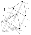
- a tractor 10 goes with a Interface, the six in the manner of a hexapod arranged hydraulic cylinders 12, 14, 16, 18, 20, 22 contains, the one ends in the rear area 24 of the work vehicle 10 and at the other end at the corner points of a vehicle-side Coupling triangle 26 are articulated. Details of a such mounting interface are in the post-published DE-A-199 51 840 described in more detail. Behind the tractor 10 there is a working tool, namely a plow 28 on which a coupling triangle 30 on the device side is attached. The Device-side coupling triangle 30 can be done in the usual way with the vehicle-side coupling triangle 26, for example Pair like a Weiste triangle.
- the signals of the two Cameras 34, 36 by an electronic one Image processing device 38 evaluated.
- the Image processing device 38 analyzes the images of the two cameras 34, 36 in terms of characteristic Picture elements and determined using known ones Image processing methods the spatial coordinates X1, Y1, Z1, ⁇ 1, ⁇ 1, and ⁇ 1 of the device-side coupling triangle 30 in Regarding the position of the vehicle body.
- displacement sensors 40 integrated, whose Output signals the respective stroke of the hydraulic cylinders 12, 14, 16, 18, 20, 22 corresponds.
- an electronic hexapod computing unit 42 calculates the spatial coordinates X, Y, Z, ⁇ , ⁇ , ⁇ of the vehicle side Coupling triangle or the vehicle-side coupling points in relation on the position of the fuselage.
- Control device 44 communicated which of these coordinates calculates the first section 46 of a trajectory. It is the first section 46 of the trajectory a straight line that defines the starting coordinates X, Y, Z, ⁇ , ⁇ , and ⁇ , the coupling frame on the vehicle side with the coordinates a target point 48, which is in a fixed spatial relation stands to the coupling frame 30 on the device side, connects.
- the rectilinear trajectory can coordinate rotations be overlaid.
- the control unit 44 there is a second fixed one Trajectory 50 saved by a learning mode has been determined and which depends on the type of concrete Coupling mechanism depends.
- the control device 44 is connected to an activation switch 52 which can be actuated by an operator. If an activation signal is emitted by the activation switch 52, the control unit 44 calculates control signals for proportional valves 54 from the first and the second movement path 46, 50, which supply corresponding oil quantities to the respective hydraulic cylinders 12, 14, 16, 18, 20, 22, so that these are extended or retracted in order to move the coupling frame 26 on the vehicle along the movement paths 46, 50 and to automatically approach the coupling frame 30 on the device and to carry out the coupling process. Furthermore, an operating unit 56, for example a joystick, which can be actuated by the operator is provided, which is connected to the control device 44 and serves for manual operation of the attachment interface.
- an operating unit 56 for example a joystick
- Fig. 5 In the embodiment shown in Fig. 5 are used for Scanning the coupling area instead of that in Fig. 1st optical cameras shown five laser sensors 70, 72, 74, 76, 78 used, each consisting of a transmitter and a Recipients exist.
- the laser sensors can be moved sideways pivot. They are arranged so that each laser sensor is aligned with an associated vertical plane.
- the Horizontal levels of the laser sensors are around one another given values offset by a distance h. From the scanned data from the laser sensors can be spatially Create a picture of the attachment area. Striking elements of the device 28 or the coupling triangle 30 are by the Evaluation device recognized, so that from this Have device-related coordinates calculated.
- the evaluation of the Data and control of the hexapod can be done in a similar way done as it is based on optical image processing has been described.
Landscapes
- Life Sciences & Earth Sciences (AREA)
- Engineering & Computer Science (AREA)
- Mechanical Engineering (AREA)
- Zoology (AREA)
- Soil Sciences (AREA)
- Environmental Sciences (AREA)
- Transportation (AREA)
- Control Of Position, Course, Altitude, Or Attitude Of Moving Bodies (AREA)
- Guiding Agricultural Machines (AREA)
- Agricultural Machines (AREA)
Applications Claiming Priority (2)
| Application Number | Priority Date | Filing Date | Title |
|---|---|---|---|
| DE10111529A DE10111529A1 (de) | 2001-03-10 | 2001-03-10 | Vorrichtung zum Koppeln eines Gerätes an einem Arbeitsfahrzeug |
| DE10111529 | 2001-03-10 |
Publications (2)
| Publication Number | Publication Date |
|---|---|
| EP1238577A1 true EP1238577A1 (fr) | 2002-09-11 |
| EP1238577B1 EP1238577B1 (fr) | 2006-06-21 |
Family
ID=7676965
Family Applications (1)
| Application Number | Title | Priority Date | Filing Date |
|---|---|---|---|
| EP02004793A Expired - Lifetime EP1238577B1 (fr) | 2001-03-10 | 2002-03-02 | Dispositif pour coupler un appareil à un véhicule |
Country Status (4)
| Country | Link |
|---|---|
| US (1) | US6581695B2 (fr) |
| EP (1) | EP1238577B1 (fr) |
| AT (1) | ATE330454T1 (fr) |
| DE (2) | DE10111529A1 (fr) |
Cited By (14)
| Publication number | Priority date | Publication date | Assignee | Title |
|---|---|---|---|---|
| DE102006025698A1 (de) * | 2006-06-01 | 2007-12-06 | Alois Pöttinger Maschinenfabrik Gmbh | Verfahren und Vorrichtung zur Steuerung des Anspannens einer Landmaschine an einen Schlepper |
| EP2155507A4 (fr) * | 2007-01-25 | 2011-03-09 | Target Hitch Llc | Guidage d'un véhicule tracteur pour connexion d'un attelage de remorque |
| EP2520447A1 (fr) * | 2011-05-03 | 2012-11-07 | CNH Italia S.p.A. | Système et procédé de positionnement d'un véhicule avec un attelage à l'aide d'un système de direction automatique |
| US8888121B2 (en) | 2007-01-25 | 2014-11-18 | Target Hitch Llc | Towing vehicle guidance for trailer hitch connection |
| WO2016000893A1 (fr) | 2014-07-02 | 2016-01-07 | Zf Friedrichshafen Ag | Dispositif et procédé de détection d'un angle de pivotement entre un véhicule et une remorque |
| CN105960871A (zh) * | 2016-06-13 | 2016-09-28 | 福建农林大学 | 一种农机具三孔销式挂接装置 |
| EP3143854A1 (fr) * | 2015-09-17 | 2017-03-22 | CLAAS Tractor S.A.S. | Engin agricole |
| EP3178302A1 (fr) * | 2015-12-10 | 2017-06-14 | Robert Bosch Gmbh | Dispositif et procédé de réglage du fonctionnement d'un appareil de remorquage hydraulique d'un véhicule |
| EP3300560A1 (fr) * | 2016-09-29 | 2018-04-04 | Robert Bosch GmbH | Dispositif et procédé de réglage du fonctionnement d'un appareil de remorquage hydraulique d'un véhicule |
| EP3300558A1 (fr) * | 2016-09-29 | 2018-04-04 | Robert Bosch GmbH | Dispositif et procédé de réglage du fonctionnement d'un appareil isolé hydraulique d'un véhicule |
| WO2018192984A1 (fr) * | 2017-04-19 | 2018-10-25 | Robert Bosch Gmbh | Procédés et systèmes d'alignement d'un véhicule sur une remorque |
| DE102017119969A1 (de) * | 2017-08-31 | 2019-02-28 | Saf-Holland Gmbh | Anhänger-Steuervorrichtung zum Montieren an einem Anhänger |
| EP3470247A1 (fr) * | 2017-10-13 | 2019-04-17 | Deere & Company | Procédé de support d'un processus d'attelage |
| EP3922495A1 (fr) | 2020-06-10 | 2021-12-15 | CLAAS Tractor S.A.S. | Véhicule de travail agricole |
Families Citing this family (89)
| Publication number | Priority date | Publication date | Assignee | Title |
|---|---|---|---|---|
| US8478492B2 (en) | 1998-11-27 | 2013-07-02 | Caterpillar Trimble Control Technologies, Inc. | Method and system for performing non-contact based determination of the position of an implement |
| JP3759429B2 (ja) * | 2001-05-23 | 2006-03-22 | 株式会社東芝 | 障害物検出装置及びその方法 |
| US20040188105A1 (en) * | 2002-03-20 | 2004-09-30 | Patrick Newnam | Method of earthworking |
| DE10232909A1 (de) * | 2002-07-19 | 2004-01-29 | Deere & Company, Moline | Kabinenlagerung für eine Fahrzeugkabine |
| US6663132B1 (en) * | 2002-09-23 | 2003-12-16 | The United States Of America As Represented By The Secretary Of The Army | Remotely controlled electro-hydraulic towing assembly |
| DE10247058A1 (de) | 2002-10-09 | 2004-04-22 | Deere & Company, Moline | Geräteschnittstelle zur Kopplung von Arbeitsgeräten an ein Arbeitsfahrzeug und Ventilanordnung |
| DE10302545A1 (de) * | 2003-01-23 | 2004-07-29 | Conti Temic Microelectronic Gmbh | Automatisches Ankuppel bzw. Andocken mittels 2D- und 3D-Bildsensorik |
| DE10331948A1 (de) * | 2003-07-15 | 2005-02-24 | Valeo Schalter Und Sensoren Gmbh | Verfahren und System zur Unterstützung des Manövrierens von Fahrzeugen |
| DE10342403A1 (de) * | 2003-09-13 | 2005-04-07 | Deere & Company, Moline | Vorrichtung zur Kopplung eines Arbeitsgeräts an ein Arbeitsfahrzeug |
| US7171769B2 (en) * | 2004-02-12 | 2007-02-06 | Sno-Way International, Inc. | Hitch system using a video camera to facilitate hitch alignment |
| DE102004029129B4 (de) * | 2004-06-17 | 2008-08-28 | Daimler Ag | Verfahren und Vorrichtung zur Ankupplung eines Anhängers an ein Kraftfahrzeug |
| DE102004029130A1 (de) * | 2004-06-17 | 2005-12-29 | Daimlerchrysler Ag | Verfahren zur Ankupplung eines Anhängers an ein Kraftfahrzeug |
| US10458099B2 (en) | 2004-08-26 | 2019-10-29 | Caterpillar Trimble Control Technologies Llc | Auto recognition of at least one standoff target to determine position information for a mobile machine |
| US20060118313A1 (en) * | 2004-12-08 | 2006-06-08 | Nicholas James A | Surface-contouring implement |
| DE102004059596B4 (de) * | 2004-12-09 | 2007-11-08 | Daimlerchrysler Ag | Verfahren zum Ermitteln eines Knickwinkels eines Fahrzeuggespanns sowie entsprechende Vorrichtung |
| US7490678B2 (en) * | 2005-04-21 | 2009-02-17 | A.I.L., Inc. | GPS controlled guidance system for farm tractor/implement combination |
| US7623952B2 (en) * | 2005-04-21 | 2009-11-24 | A.I.L., Inc. | GPS controlled guidance system for farm tractor/implement combination |
| US7762051B2 (en) * | 2005-07-15 | 2010-07-27 | Cnh America Llc | System for removal of agricultural header |
| US20070234597A1 (en) * | 2006-03-29 | 2007-10-11 | Schpok Ricky K | Snowplow attachment system and method |
| DE102007039687A1 (de) * | 2007-08-22 | 2009-03-05 | Deutsches Zentrum für Luft- und Raumfahrt e.V. | Vorrichtung zur Durchführung eines Kupplungsvorganges |
| JP5227139B2 (ja) * | 2008-11-12 | 2013-07-03 | 株式会社トプコン | 建設機械 |
| US20110050903A1 (en) * | 2009-04-08 | 2011-03-03 | Topcon Positioning Systems, Inc. | Method for determining position and orientation of vehicle trailers |
| US8214108B2 (en) * | 2009-06-10 | 2012-07-03 | Honda Motor Co., Ltd. | Vehicle system and method for selectively coupled vehicles |
| DE102010004920A1 (de) * | 2010-01-19 | 2011-07-21 | ZF Lenksysteme GmbH, 73527 | Vorrichtung zur Unterstützung des Ankuppelns eines Anhängers an eine Anhängerkupplung eines Kraftfahrzeugs und Verfahren |
| US8843340B2 (en) | 2010-06-23 | 2014-09-23 | Aisin Aw Co., Ltd. | Track information generating device, track information generating method, and computer-readable storage medium |
| DE102010050790A1 (de) | 2010-11-10 | 2012-05-10 | Claas Selbstfahrende Erntemaschinen Gmbh | Verfahren zur Lokalisierung eines landwirtschaftlichen Arbeitsgerätes |
| US9340150B2 (en) * | 2011-12-28 | 2016-05-17 | Agco Corporation | Articulated machine proximity system |
| DE102012007855B4 (de) | 2012-04-16 | 2018-07-26 | Technische Universität Dresden | Modulares System zur Manipulation vonWerkzeugen für mobile Arbeitsmaschinen |
| US9957692B2 (en) * | 2013-03-15 | 2018-05-01 | Hexagon Technology Center Gmbh | System and method for heavy equipment navigation and working edge positioning using an image acquisition device that provides distance information |
| US9121703B1 (en) * | 2013-06-13 | 2015-09-01 | Google Inc. | Methods and systems for controlling operation of a laser device |
| NO20130966A1 (no) * | 2013-07-11 | 2015-01-12 | Smart Patents As | System og fremgangsmåte for automatisk å koble en tilhenger til et kjøretøy |
| US10556473B2 (en) | 2013-07-11 | 2020-02-11 | Smart Patents As | System and method for connecting or disconnecting a trailer to a vehicle |
| DE112014004554T5 (de) * | 2013-11-18 | 2016-07-07 | Robert Bosch Gmbh | Draufsicht auf Anhängerkupplungsverbindung |
| US20160302357A1 (en) * | 2013-12-05 | 2016-10-20 | Agco Corporation | Combine header hook-up assist system |
| GB201322771D0 (en) * | 2013-12-20 | 2014-02-05 | Agco Int Gmbh | Agricultural implement mounting |
| GB201322746D0 (en) * | 2013-12-20 | 2014-02-05 | Agco Int Gmbh | Agricultural implement connection control |
| US20160016470A1 (en) * | 2014-03-25 | 2016-01-21 | Agco International Gmbh | Tractor control/display systems |
| CN105082910B (zh) * | 2014-05-07 | 2018-01-26 | 通用汽车环球科技运作有限责任公司 | 辅助将运载工具联接至拖车的系统和方法 |
| US20160039480A1 (en) * | 2014-08-05 | 2016-02-11 | Agco International Gmbh | Tractor control system |
| US20160312432A1 (en) * | 2015-04-23 | 2016-10-27 | Caterpillar Inc. | Computer Vision Assisted Work Tool Recognition and Installation |
| JP6850078B2 (ja) * | 2016-03-23 | 2021-03-31 | 株式会社小松製作所 | モータグレーダ |
| US9738125B1 (en) | 2016-05-17 | 2017-08-22 | Horizon Global Americas Inc. | Communication device, system, and method for active control of external vehicle components |
| GB2550847B (en) * | 2016-05-23 | 2019-02-20 | Hiltec Designs Ltd | Coupler with contactless attachment engagement detection |
| CA3238055A1 (fr) * | 2016-12-16 | 2018-06-21 | Agco Corporation | Barre porte-outils de labour en courbes de niveaux d'instrument |
| EP3379222B1 (fr) | 2017-03-22 | 2020-12-30 | Methode Electronics Malta Ltd. | Ensemble de capteur à base magnétoélastique |
| US11229152B2 (en) | 2017-05-12 | 2022-01-25 | Deere & Company | Ground-engaging implement with lateral position adjustment |
| US10492360B2 (en) | 2017-05-12 | 2019-12-03 | Deere & Company | Ground-engaging implement with lateral position adjustment |
| US10485154B2 (en) | 2017-05-12 | 2019-11-26 | Deere & Company | Ground-engaging implement with lateral position adjustment |
| US10485161B2 (en) * | 2017-05-12 | 2019-11-26 | Deere & Company | Ground-engaging implement with lateral position adjustment |
| US10617057B2 (en) | 2017-05-12 | 2020-04-14 | Deere & Company | Ground-engaging implement with lateral position adjustment |
| IT201700054083A1 (it) * | 2017-05-18 | 2018-11-18 | Cnh Ind Italia Spa | Sistema e metodo di collegamento automatico tra trattore ed attrezzo |
| DE102017209707A1 (de) * | 2017-06-08 | 2018-12-13 | Kässbohrer Geländefahrzeug AG | Vorrichtung zur Steuerung von Bewegungen eines front- oder heckseitigen Anbaugeräts einer Pistenraupe und Pistenraupe |
| DE102017210054A1 (de) | 2017-06-14 | 2018-12-20 | Deere & Company | Landwirtschaftliches Arbeitsfahrzeug mit Mitteln zur optimierten Positionierung einer an einer verstellbaren Schnittstelle angebrachten Last für eine Straßenfahrt |
| US10858809B2 (en) | 2017-11-03 | 2020-12-08 | Peter J. Mollick | System for machine and implement control |
| WO2019090369A2 (fr) * | 2017-11-03 | 2019-05-09 | Mollick Peter J | Système de commande de machine et d'outil |
| US10667507B2 (en) * | 2017-12-11 | 2020-06-02 | Cnh Industrial America Llc | Front-boom sprayer with a boom center section and lift arm arrangement for improved field of view |
| US11991942B2 (en) * | 2018-06-29 | 2024-05-28 | Dcentralized Systems, Inc. | Implement attachment system for autonomous modular ground utility robot system |
| DE18907724T1 (de) | 2018-02-27 | 2021-03-25 | Methode Electronics, Inc. | Schleppsysteme und Verfahren mit Verwendung von Magnetfeldmessung |
| US11221262B2 (en) | 2018-02-27 | 2022-01-11 | Methode Electronics, Inc. | Towing systems and methods using magnetic field sensing |
| US11491832B2 (en) | 2018-02-27 | 2022-11-08 | Methode Electronics, Inc. | Towing systems and methods using magnetic field sensing |
| US11135882B2 (en) | 2018-02-27 | 2021-10-05 | Methode Electronics, Inc. | Towing systems and methods using magnetic field sensing |
| US11084342B2 (en) | 2018-02-27 | 2021-08-10 | Methode Electronics, Inc. | Towing systems and methods using magnetic field sensing |
| US11014417B2 (en) | 2018-02-27 | 2021-05-25 | Methode Electronics, Inc. | Towing systems and methods using magnetic field sensing |
| US11162241B2 (en) | 2018-03-27 | 2021-11-02 | Deere & Company | Controlling mobile machines with a robotic attachment |
| JP2019170309A (ja) * | 2018-03-29 | 2019-10-10 | ヤンマー株式会社 | 作業車両 |
| US11690308B2 (en) * | 2018-05-14 | 2023-07-04 | Cnh Industrial America Llc | System and method for controlling the operation of an agricultural implement being towed by a work vehicle |
| UA130013C2 (uk) | 2019-08-22 | 2025-10-15 | Грейт Плейнз Мануфекчєрінг, Інк. | Автономна сільськогосподарська система (варіанти) |
| US11105351B2 (en) | 2019-09-20 | 2021-08-31 | Cnh Industrial America Llc | Agricultural baler with hydraulic flow controller |
| US11770991B2 (en) * | 2019-10-31 | 2023-10-03 | Deere & Company | Vehicle connection guidance |
| US11212953B2 (en) | 2019-10-31 | 2022-01-04 | Deere & Company | Vehicle attachment carrier loading guidance |
| JP7074119B2 (ja) * | 2019-12-25 | 2022-05-24 | 井関農機株式会社 | 作業車両 |
| JP7276547B2 (ja) * | 2019-12-25 | 2023-05-18 | 井関農機株式会社 | トラクタ |
| US12150444B2 (en) | 2019-12-30 | 2024-11-26 | Agco Corporation | Sprayer vehicle comprising telescoping parallel linkage and related methods |
| US11856895B2 (en) | 2019-12-30 | 2024-01-02 | Agco Corporation | Baler slacker arm sensor for protecting against needle over-tension conditions |
| AU2021208629C1 (en) * | 2020-01-15 | 2025-01-23 | Great Plains Manufacturing, Inc. | Autonomous agricultural system |
| DE102020200913A1 (de) | 2020-01-27 | 2021-07-29 | Robert Bosch Gesellschaft mit beschränkter Haftung | Verfahren zur Steuerung einer Anfahrt eines Nutzfahrzeugs |
| US12016257B2 (en) | 2020-02-19 | 2024-06-25 | Sabanto, Inc. | Methods for detecting and clearing debris from planter gauge wheels, closing wheels and seed tubes |
| NO346568B1 (en) | 2020-05-29 | 2022-10-10 | Smart Patents As | Trailer coupling assembly and vehicle with trailer coupling assembly |
| US12461083B2 (en) | 2020-08-03 | 2025-11-04 | Sabanto, Inc. | Methods for improved agricultural procedures |
| US11634891B2 (en) * | 2020-10-08 | 2023-04-25 | Deere & Company | System and method for navigating an operator to couple a self-propelled vehicle with an attachment implement therefor |
| US12134348B2 (en) | 2021-04-14 | 2024-11-05 | Deere & Company | System and method providing visual aids for workpiece manipulator positioning and movement preview path |
| DE102021119686A1 (de) | 2021-07-29 | 2023-02-02 | Deere & Company | Verfahren zur Unterstützung eines an einer landwirtschaftlichen Anbaugeräteschnittstelle durchzuführenden Kuppelvorgangs |
| DE102021119683A1 (de) * | 2021-07-29 | 2023-02-02 | Deere & Company | Verfahren zur Unterstützung eines an einem Dreipunkt-Kraftheber durchzuführenden Kuppelvorgangs |
| DE102021209167B4 (de) * | 2021-08-20 | 2023-07-06 | Zf Friedrichshafen Ag | Verbindungssystem und Zugmaschinenverbund |
| US20230127547A1 (en) * | 2021-10-25 | 2023-04-27 | Deere & Company | Smart unloading of implement head on trailer |
| US12146299B2 (en) * | 2022-04-20 | 2024-11-19 | Deere & Company | System and method providing overlays for assisting coupling loaders with implements |
| US12606089B2 (en) | 2023-07-21 | 2026-04-21 | Deere & Company | Method and apparatus for loader positioning and load handling using vision system |
| US12488630B2 (en) | 2023-07-21 | 2025-12-02 | Deere & Company | Method and apparatus monitoring operation of a work vehicle attachment for scheduling maintenance |
| US20260001377A1 (en) * | 2024-06-28 | 2026-01-01 | Deere & Company | Agricultural header transport system |
Citations (3)
| Publication number | Priority date | Publication date | Assignee | Title |
|---|---|---|---|---|
| US3432184A (en) * | 1967-07-10 | 1969-03-11 | United States Steel Corp | Power actuated tractor hitch |
| US5455557A (en) * | 1993-02-10 | 1995-10-03 | Robert Bosch Gmbh | Auxiliary back-up and trailer coupling device for motor vehicles |
| DE19913911A1 (de) * | 1998-03-26 | 1999-10-21 | Erwin Francke | Docking-System für das automatische Ankoppeln der Versorgungsleitung bei Sattelaufliegern |
Family Cites Families (5)
| Publication number | Priority date | Publication date | Assignee | Title |
|---|---|---|---|---|
| FR2649580B1 (fr) | 1989-07-13 | 1992-02-07 | Defrancq Hubert | Systeme d'attelage et de relevage pour un outil, notamment agricole, propre a etre monte a l'avant d'un tracteur |
| DE4213355A1 (de) * | 1992-04-23 | 1993-10-28 | Milan Jermen | System der automatischen Verbindung des Traktors mit den anzuschließenden Geräten und Maschinen |
| US6076847A (en) | 1998-08-26 | 2000-06-20 | Thornton; Morris E. | Trailer hitch alignment device |
| DE19950808A1 (de) * | 1999-10-21 | 2001-04-26 | Zuern Gmbh & Co | Vorrichtung und Verfahren zum Verbinden eines Anhängers mit einem Zugfahrzeug |
| DE19951840B4 (de) | 1999-10-28 | 2009-01-08 | Deere & Company, Moline | Anbauschnittstelle zur Kopplung von Arbeitsgeräten an ein Arbeitsfahrzeug |
-
2001
- 2001-03-10 DE DE10111529A patent/DE10111529A1/de not_active Withdrawn
-
2002
- 2002-01-29 US US10/058,937 patent/US6581695B2/en not_active Expired - Lifetime
- 2002-03-02 EP EP02004793A patent/EP1238577B1/fr not_active Expired - Lifetime
- 2002-03-02 DE DE50207242T patent/DE50207242D1/de not_active Expired - Lifetime
- 2002-03-02 AT AT02004793T patent/ATE330454T1/de active
Patent Citations (3)
| Publication number | Priority date | Publication date | Assignee | Title |
|---|---|---|---|---|
| US3432184A (en) * | 1967-07-10 | 1969-03-11 | United States Steel Corp | Power actuated tractor hitch |
| US5455557A (en) * | 1993-02-10 | 1995-10-03 | Robert Bosch Gmbh | Auxiliary back-up and trailer coupling device for motor vehicles |
| DE19913911A1 (de) * | 1998-03-26 | 1999-10-21 | Erwin Francke | Docking-System für das automatische Ankoppeln der Versorgungsleitung bei Sattelaufliegern |
Cited By (26)
| Publication number | Priority date | Publication date | Assignee | Title |
|---|---|---|---|---|
| DE102006025698A1 (de) * | 2006-06-01 | 2007-12-06 | Alois Pöttinger Maschinenfabrik Gmbh | Verfahren und Vorrichtung zur Steuerung des Anspannens einer Landmaschine an einen Schlepper |
| EP1862050A3 (fr) * | 2006-06-01 | 2008-02-06 | Alois Pöttinger Maschinenfabrik Ges. m.b.H. | Procédé et dispositif destinés à la commande de l'attache d'une machine agricole sur une remorque |
| EP2155507A4 (fr) * | 2007-01-25 | 2011-03-09 | Target Hitch Llc | Guidage d'un véhicule tracteur pour connexion d'un attelage de remorque |
| US8888120B2 (en) | 2007-01-25 | 2014-11-18 | Target Hitch Llc | Towing vehicle guidance for trailer hitch connection |
| US8888121B2 (en) | 2007-01-25 | 2014-11-18 | Target Hitch Llc | Towing vehicle guidance for trailer hitch connection |
| EP2520447A1 (fr) * | 2011-05-03 | 2012-11-07 | CNH Italia S.p.A. | Système et procédé de positionnement d'un véhicule avec un attelage à l'aide d'un système de direction automatique |
| WO2016000893A1 (fr) | 2014-07-02 | 2016-01-07 | Zf Friedrichshafen Ag | Dispositif et procédé de détection d'un angle de pivotement entre un véhicule et une remorque |
| DE102014212821A1 (de) | 2014-07-02 | 2016-01-07 | Zf Friedrichshafen Ag | Vorrichtung und Verfahren zur Erfassung eines Schwenkwinkels zwischen einem Fahrzeug und einer Anhängervorrichtung |
| US10414221B2 (en) | 2014-07-02 | 2019-09-17 | Zf Friedrichshafen Ag | Device and method for detecting a pivot angle between a vehicle and a trailer device |
| EP3143854A1 (fr) * | 2015-09-17 | 2017-03-22 | CLAAS Tractor S.A.S. | Engin agricole |
| EP3178302A1 (fr) * | 2015-12-10 | 2017-06-14 | Robert Bosch Gmbh | Dispositif et procédé de réglage du fonctionnement d'un appareil de remorquage hydraulique d'un véhicule |
| US10306821B2 (en) | 2015-12-10 | 2019-06-04 | Robert Bosch Gmbh | Device and method for controlling the operation of a towed implement, which can be activated hydraulically, on a vehicle |
| CN105960871A (zh) * | 2016-06-13 | 2016-09-28 | 福建农林大学 | 一种农机具三孔销式挂接装置 |
| EP3300558A1 (fr) * | 2016-09-29 | 2018-04-04 | Robert Bosch GmbH | Dispositif et procédé de réglage du fonctionnement d'un appareil isolé hydraulique d'un véhicule |
| EP3300560A1 (fr) * | 2016-09-29 | 2018-04-04 | Robert Bosch GmbH | Dispositif et procédé de réglage du fonctionnement d'un appareil de remorquage hydraulique d'un véhicule |
| WO2018192984A1 (fr) * | 2017-04-19 | 2018-10-25 | Robert Bosch Gmbh | Procédés et systèmes d'alignement d'un véhicule sur une remorque |
| US11279282B2 (en) | 2017-04-19 | 2022-03-22 | Robert Bosch Gmbh | Methods and systems for aligning a vehicle with a trailer |
| AU2018253868B2 (en) * | 2017-04-19 | 2023-12-21 | Robert Bosch Gmbh | Methods and systems for aligning a vehicle with a trailer |
| DE102017119969A1 (de) * | 2017-08-31 | 2019-02-28 | Saf-Holland Gmbh | Anhänger-Steuervorrichtung zum Montieren an einem Anhänger |
| US11511578B2 (en) | 2017-08-31 | 2022-11-29 | Saf-Holland Gmbh | Trailer controller for mounting on a trailer |
| DE102017119969B4 (de) | 2017-08-31 | 2023-01-05 | Saf-Holland Gmbh | Anhänger mit einer Anhänger-Steuervorrichtung, Ankupplungssystem und Verfahren zur Durchführung eines Kupplungsprozesses |
| EP3470247A1 (fr) * | 2017-10-13 | 2019-04-17 | Deere & Company | Procédé de support d'un processus d'attelage |
| US11007830B2 (en) | 2017-10-13 | 2021-05-18 | Deere & Company | Method for assisting a hitching operation |
| EP3922495A1 (fr) | 2020-06-10 | 2021-12-15 | CLAAS Tractor S.A.S. | Véhicule de travail agricole |
| DE102020115466A1 (de) | 2020-06-10 | 2021-12-16 | CLAAS Tractor S.A.S | Landwirtschaftliches Arbeitsfahrzeug |
| US12162411B2 (en) | 2020-06-10 | 2024-12-10 | Claas Tractor Sas | Agricultural work vehicle |
Also Published As
| Publication number | Publication date |
|---|---|
| DE50207242D1 (de) | 2006-08-03 |
| US6581695B2 (en) | 2003-06-24 |
| EP1238577B1 (fr) | 2006-06-21 |
| DE10111529A1 (de) | 2002-09-12 |
| ATE330454T1 (de) | 2006-07-15 |
| US20020125018A1 (en) | 2002-09-12 |
Similar Documents
| Publication | Publication Date | Title |
|---|---|---|
| EP1238577B1 (fr) | Dispositif pour coupler un appareil à un véhicule | |
| DE10145150B4 (de) | Verfahren zur Einstellung eines Kurses eines mobilen Roboters | |
| EP3408719B1 (fr) | Procédé de création d'une carte d'environnement pour un appareil de traitement à déplacement autonome | |
| EP0714592B1 (fr) | Système de commande pour le réglage de position de dispositifs d'attelage | |
| EP3470247B1 (fr) | Procédé de support d'un processus d'attelage | |
| EP3932162B1 (fr) | Système de détermination de la position d'une caméra dans un dispositif caméra par rapport à un niveau de plancher | |
| EP0378528B1 (fr) | Procede pour guider un vehicule automoteur et vehicule automoteur | |
| EP2283719A2 (fr) | Agencement pour l'installation réglable latéralement d'un appareil agricole sur un véhicule | |
| DE102008015277A1 (de) | Verfahren und Vorrichtung zur Lenkung einer zweiten landwirtschaftlichen Maschine, die relativ zu einer ersten landwirtschaftlichen Maschine über ein Feld lenkbar ist | |
| EP3254902A1 (fr) | Dispositif de surveillance de l'environnement d'un véhicule automobile, son procédé de fonctionnement et véhicule automobile en étant équipé | |
| DE102017113245A1 (de) | Verfahren und Vorrichtung zum Erkennen von Tieren in der Fahrgasse einer landwirtschaftlichen Feldbearbeitungsmaschine | |
| DE102020124985A1 (de) | Unterscheiden zwischen nahem anhänger und verbundenem anhänger | |
| DE102020121899A1 (de) | System zum ausrichten einer standort-kennung einer fahrzeugkupplung mit einem anhängerkoppler | |
| DE102016117237A1 (de) | Verfahren zum mechanischen Koppeln eines Anbaugerätes mit einem Zugfahrzeug oder einer Anhängevorrichtung | |
| DE10129136A1 (de) | Einrichtung zur selbsttätigen Lenkung eines landwirtschaftlichen Arbeitsfahrzeugs | |
| EP2042352B1 (fr) | Dispositif et procédé d'accouplement d'une remorque sur un véhicule de traction agricole | |
| DE102019121550A1 (de) | Transporteinheit und System zum Transport eines Objekts | |
| EP3818799B1 (fr) | Machine de travail agricole | |
| DE102009047181A1 (de) | Landwirtschaftliches Bodenbearbeitungsgerät zur Befestigung an einem Fahrzeug | |
| EP3738420B1 (fr) | Procédé de fonctionnement d'un engin agricole automatique | |
| DE102020123882A1 (de) | Verfahren mit festem versatz zur kupplungsdetektion während eines kupplungsassistenzvorgangs | |
| DE112020007380T5 (de) | Klappbare maschine, panoramischesrundumsicht-system und kalibrierungsverfahren für dieses system | |
| EP3521860B1 (fr) | Dispositif capteur optoélectronique | |
| EP3922495B1 (fr) | Véhicule de travail agricole | |
| EP3300560B1 (fr) | Dispositif et procédé de réglage du fonctionnement d'un appareil de remorquage hydraulique d'un véhicule |
Legal Events
| Date | Code | Title | Description |
|---|---|---|---|
| PUAI | Public reference made under article 153(3) epc to a published international application that has entered the european phase |
Free format text: ORIGINAL CODE: 0009012 |
|
| AK | Designated contracting states |
Kind code of ref document: A1 Designated state(s): AT BE CH CY DE DK ES FI FR GB GR IE IT LI LU MC NL PT SE TR |
|
| AX | Request for extension of the european patent |
Free format text: AL;LT;LV;MK;RO;SI |
|
| 17P | Request for examination filed |
Effective date: 20030311 |
|
| AKX | Designation fees paid |
Designated state(s): AT DE FI FR GB IT |
|
| GRAP | Despatch of communication of intention to grant a patent |
Free format text: ORIGINAL CODE: EPIDOSNIGR1 |
|
| GRAS | Grant fee paid |
Free format text: ORIGINAL CODE: EPIDOSNIGR3 |
|
| GRAA | (expected) grant |
Free format text: ORIGINAL CODE: 0009210 |
|
| AK | Designated contracting states |
Kind code of ref document: B1 Designated state(s): AT DE FI FR GB IT |
|
| PG25 | Lapsed in a contracting state [announced via postgrant information from national office to epo] |
Ref country code: IT Free format text: LAPSE BECAUSE OF FAILURE TO SUBMIT A TRANSLATION OF THE DESCRIPTION OR TO PAY THE FEE WITHIN THE PRESCRIBED TIME-LIMIT;WARNING: LAPSES OF ITALIAN PATENTS WITH EFFECTIVE DATE BEFORE 2007 MAY HAVE OCCURRED AT ANY TIME BEFORE 2007. THE CORRECT EFFECTIVE DATE MAY BE DIFFERENT FROM THE ONE RECORDED. Effective date: 20060621 |
|
| REG | Reference to a national code |
Ref country code: GB Ref legal event code: FG4D Free format text: NOT ENGLISH |
|
| REF | Corresponds to: |
Ref document number: 50207242 Country of ref document: DE Date of ref document: 20060803 Kind code of ref document: P |
|
| GBT | Gb: translation of ep patent filed (gb section 77(6)(a)/1977) |
Effective date: 20060821 |
|
| ET | Fr: translation filed | ||
| PLBE | No opposition filed within time limit |
Free format text: ORIGINAL CODE: 0009261 |
|
| STAA | Information on the status of an ep patent application or granted ep patent |
Free format text: STATUS: NO OPPOSITION FILED WITHIN TIME LIMIT |
|
| 26N | No opposition filed |
Effective date: 20070322 |
|
| PGFP | Annual fee paid to national office [announced via postgrant information from national office to epo] |
Ref country code: IT Payment date: 20070517 Year of fee payment: 6 |
|
| PG25 | Lapsed in a contracting state [announced via postgrant information from national office to epo] |
Ref country code: IT Free format text: LAPSE BECAUSE OF NON-PAYMENT OF DUE FEES Effective date: 20080302 |
|
| PGFP | Annual fee paid to national office [announced via postgrant information from national office to epo] |
Ref country code: FI Payment date: 20140327 Year of fee payment: 13 |
|
| PGFP | Annual fee paid to national office [announced via postgrant information from national office to epo] |
Ref country code: AT Payment date: 20140219 Year of fee payment: 13 |
|
| PG25 | Lapsed in a contracting state [announced via postgrant information from national office to epo] |
Ref country code: FI Free format text: LAPSE BECAUSE OF NON-PAYMENT OF DUE FEES Effective date: 20150302 |
|
| REG | Reference to a national code |
Ref country code: AT Ref legal event code: MM01 Ref document number: 330454 Country of ref document: AT Kind code of ref document: T Effective date: 20150302 |
|
| PG25 | Lapsed in a contracting state [announced via postgrant information from national office to epo] |
Ref country code: AT Free format text: LAPSE BECAUSE OF NON-PAYMENT OF DUE FEES Effective date: 20150302 |
|
| REG | Reference to a national code |
Ref country code: FR Ref legal event code: PLFP Year of fee payment: 15 |
|
| REG | Reference to a national code |
Ref country code: FR Ref legal event code: PLFP Year of fee payment: 16 |
|
| REG | Reference to a national code |
Ref country code: FR Ref legal event code: PLFP Year of fee payment: 17 |
|
| PGFP | Annual fee paid to national office [announced via postgrant information from national office to epo] |
Ref country code: GB Payment date: 20200327 Year of fee payment: 19 |
|
| PGFP | Annual fee paid to national office [announced via postgrant information from national office to epo] |
Ref country code: FR Payment date: 20200325 Year of fee payment: 19 |
|
| PGFP | Annual fee paid to national office [announced via postgrant information from national office to epo] |
Ref country code: DE Payment date: 20210219 Year of fee payment: 20 |
|
| GBPC | Gb: european patent ceased through non-payment of renewal fee |
Effective date: 20210302 |
|
| PG25 | Lapsed in a contracting state [announced via postgrant information from national office to epo] |
Ref country code: GB Free format text: LAPSE BECAUSE OF NON-PAYMENT OF DUE FEES Effective date: 20210302 Ref country code: FR Free format text: LAPSE BECAUSE OF NON-PAYMENT OF DUE FEES Effective date: 20210331 |
|
| REG | Reference to a national code |
Ref country code: DE Ref legal event code: R071 Ref document number: 50207242 Country of ref document: DE |