EP3521860B1 - Dispositif capteur optoélectronique - Google Patents
Dispositif capteur optoélectronique Download PDFInfo
- Publication number
- EP3521860B1 EP3521860B1 EP19151190.6A EP19151190A EP3521860B1 EP 3521860 B1 EP3521860 B1 EP 3521860B1 EP 19151190 A EP19151190 A EP 19151190A EP 3521860 B1 EP3521860 B1 EP 3521860B1
- Authority
- EP
- European Patent Office
- Prior art keywords
- distance
- ground
- floor
- expected
- sensor
- Prior art date
- Legal status (The legal status is an assumption and is not a legal conclusion. Google has not performed a legal analysis and makes no representation as to the accuracy of the status listed.)
- Active
Links
Images


Classifications
-
- G—PHYSICS
- G01—MEASURING; TESTING
- G01S—RADIO DIRECTION-FINDING; RADIO NAVIGATION; DETERMINING DISTANCE OR VELOCITY BY USE OF RADIO WAVES; LOCATING OR PRESENCE-DETECTING BY USE OF THE REFLECTION OR RERADIATION OF RADIO WAVES; ANALOGOUS ARRANGEMENTS USING OTHER WAVES
- G01S17/00—Systems using the reflection or reradiation of electromagnetic waves other than radio waves, e.g. lidar systems
- G01S17/02—Systems using the reflection of electromagnetic waves other than radio waves
- G01S17/06—Systems determining position data of a target
- G01S17/42—Simultaneous measurement of distance and other co-ordinates
-
- G—PHYSICS
- G01—MEASURING; TESTING
- G01S—RADIO DIRECTION-FINDING; RADIO NAVIGATION; DETERMINING DISTANCE OR VELOCITY BY USE OF RADIO WAVES; LOCATING OR PRESENCE-DETECTING BY USE OF THE REFLECTION OR RERADIATION OF RADIO WAVES; ANALOGOUS ARRANGEMENTS USING OTHER WAVES
- G01S17/00—Systems using the reflection or reradiation of electromagnetic waves other than radio waves, e.g. lidar systems
- G01S17/87—Combinations of systems using electromagnetic waves other than radio waves
-
- G—PHYSICS
- G01—MEASURING; TESTING
- G01S—RADIO DIRECTION-FINDING; RADIO NAVIGATION; DETERMINING DISTANCE OR VELOCITY BY USE OF RADIO WAVES; LOCATING OR PRESENCE-DETECTING BY USE OF THE REFLECTION OR RERADIATION OF RADIO WAVES; ANALOGOUS ARRANGEMENTS USING OTHER WAVES
- G01S17/00—Systems using the reflection or reradiation of electromagnetic waves other than radio waves, e.g. lidar systems
- G01S17/88—Lidar systems specially adapted for specific applications
- G01S17/93—Lidar systems specially adapted for specific applications for anti-collision purposes
- G01S17/931—Lidar systems specially adapted for specific applications for anti-collision purposes of land vehicles
-
- G—PHYSICS
- G01—MEASURING; TESTING
- G01S—RADIO DIRECTION-FINDING; RADIO NAVIGATION; DETERMINING DISTANCE OR VELOCITY BY USE OF RADIO WAVES; LOCATING OR PRESENCE-DETECTING BY USE OF THE REFLECTION OR RERADIATION OF RADIO WAVES; ANALOGOUS ARRANGEMENTS USING OTHER WAVES
- G01S7/00—Details of systems according to groups G01S13/00, G01S15/00, G01S17/00
- G01S7/48—Details of systems according to groups G01S13/00, G01S15/00, G01S17/00 of systems according to group G01S17/00
- G01S7/4802—Details of systems according to groups G01S13/00, G01S15/00, G01S17/00 of systems according to group G01S17/00 using analysis of echo signal for target characterisation; Target signature; Target cross-section
-
- G—PHYSICS
- G01—MEASURING; TESTING
- G01S—RADIO DIRECTION-FINDING; RADIO NAVIGATION; DETERMINING DISTANCE OR VELOCITY BY USE OF RADIO WAVES; LOCATING OR PRESENCE-DETECTING BY USE OF THE REFLECTION OR RERADIATION OF RADIO WAVES; ANALOGOUS ARRANGEMENTS USING OTHER WAVES
- G01S7/00—Details of systems according to groups G01S13/00, G01S15/00, G01S17/00
- G01S7/48—Details of systems according to groups G01S13/00, G01S15/00, G01S17/00 of systems according to group G01S17/00
- G01S7/4808—Evaluating distance, position or velocity data
Definitions
- the present invention relates to an optoelectronic sensor device according to the preamble of claim 1 and a method for operating such an optoelectronic sensor device according to the preamble of claim 15 with a multi-layer laser scanner which is oriented towards a floor and which determines distance information for at least one monitoring area, the at least one Monitoring area covers a floor area which forms a surface area of the floor.
- Such optoelectronic sensor devices are used in a wide variety of applications. For example, they can be attached in a stationary manner and serve to monitor a protected area of a hazardous machine. By means of the first monitoring area, e.g. the legs of people can be detected. If the presence of a person or an object in the protective space is detected by the sensor device in this way, the machine can be switched off so as not to endanger the person.
- optoelectronic sensor devices can also be used for mobile applications; in particular, they can enable vehicles and self-driving vehicles to be operated.
- Self-driving vehicles also called AGVs (Automated Guided Vehicle)
- AGVs Automate Guided Vehicle
- a laser scanner of the sensor device attached to the vehicle is usually used, which is attached at a height of about 15 to 30 cm above the ground and, for example, one oriented in the direction of travel of the vehicle Monitored area scanned.
- the laser scanner can in particular be a distance sensor, the monitoring area of which extends parallel to the floor and defines a flat surface.
- the distance sensor By mounting the distance sensor at a distance from the floor, it is possible to avoid erroneous detection of the floor as an obstacle during pitching movements of the vehicle when accelerating or braking or when driving over bumps.
- flat obstacles are not recognized either in stationary or in mobile use of the sensor device. In other words, obstacles which are lower than the distance of a monitoring area running parallel to the floor or of the distance sensor from the floor are not detected. If, for example, a self-driving vehicle collides with such obstacles, the vehicle and the obstacle can be damaged. In addition, there can also be a risk of injury, especially when using self-driving vehicles in hospitals. Even with stationary use of the sensor device, failure to detect objects can lead to safety risks.
- a complete detection of obstacles of any kind could be achieved by an expanded sensor system, for example by providing further optical sensors, for example a camera, in addition to the distance sensor to monitor the surroundings of the Detect sensor device essentially completely three-dimensional.
- Such an expansion of the sensor system is not always possible due to restrictions, for example due to the additional costs associated with it.
- the object on which the invention is based is therefore to specify an optoelectronic sensor device which can also detect flat objects and soil anomalies, the detection being carried out in the simplest and most cost-effective way possible.
- the optoelectronic sensor device has a distance sensor aligned on the floor in the form of a laser scanner, which determines distance information for at least one monitoring area, the at least one monitoring area covering a floor area which forms a surface area of the floor. Furthermore, the sensor device has an evaluation unit which is designed to use the distance information to detect a deviation from at least one expected floor area and to output a signal, in particular a warning signal, when a deviation is detected.
- the at least one expected floor area is based on a predefined model which represents the distance information for the at least one monitoring area for the theoretical case in which the distance sensor is in a known reference position and is aligned with a known reference floor.
- the monitored area partially covers the floor, i.e. comprises a surface area of the floor.
- the monitored area therefore does not run parallel to the ground, at least in sections, but rather at an angle, so that the monitored area intersects the ground in the geometric sense.
- the monitoring area thus runs inclined in the direction of the floor and intersects the floor in a specific floor area which can be assigned to the monitoring area based on the geometry of the monitoring area and the floor. In this way, it is ensured that the distance sensor always "has an eye on" the ground and, in particular, can also detect flat objects on the ground and ground anomalies.
- Several monitoring areas are preferably provided, each covering an assigned floor area.
- the detection of objects and soil anomalies takes place on the basis of the distance information, which is evaluated as a function of at least one expected soil area.
- an assigned expected floor area is preferably provided for each covered floor area.
- a respective expected floor area indicates the floor area which the device would expect with regard to the determined distance information if there is no object and also no floor anomaly.
- the expected floor area thus represents a standard area which is used to determine whether an object and / or a floor anomaly is located in the monitoring area in question.
- the expected floor area can be defined by one or more distance limit values to indicate a range of distance values between the distance sensor and the floor. If the distance information determined for the currently covered ground area is within the range of distance values it can be assumed that there is no object and no soil anomaly in the monitoring area.
- the expected floor area can be designed to be spatially variable and be defined by one or more geometrically interpretable parameters. Such parameters can in particular be distance values with regard to the distance information determined by the distance sensor, but also other parameters, for example for describing a contour in space.
- the distance sensor When the sensor device is in operation, the distance sensor preferably scans a line-shaped floor area, preferably optically, and supplies distance information, ie depth information, for the scanned line.
- the distance sensor is preferably designed as a laser scanner with a rotatable scan head which determines distance information by measuring the time of flight of laser pulses emitted by the distance sensor itself. For example, a laser pulse is emitted at periodic intervals, which provides a distance point for an assigned rotary position of the scan head. For each of the distance points determined in this way, it can be determined whether the associated distance value lies within the expected floor area.
- an associated upper and lower distance limit value can be stored for each relevant rotary position of the scan head, which is compared with the distance of the distance point determined for the relevant rotary position. If the measured distance does not exceed the upper distance value and does not fall below the lower distance limit value, the relevant distance point can be assigned to the expected floor area. This means that it is assumed that the laser pulse for measuring the distance point hit the ground and not an object or a ground anomaly. If the measured distance violates one of the distance limit values, this is an indication of an object or a soil anomaly, whereby, for example, in the case of too small distances an object can be inferred and in the case of too large distances a soil anomaly can be concluded.
- the expected floor area is based on a predefined model which represents the distance information for the at least one monitoring area for the theoretical case in which the distance sensor is in a known reference position and is aligned with a known reference floor.
- the predefined model is based on a priori knowledge, in particular about a mounting bracket and / or a mounting position of the distance sensor.
- the expected soil area represents a model-based reference for the detection of objects and soil anomalies.
- the determined distance information preferably does not have to match the predefined model exactly in order to rule out an object or a soil anomaly. Rather, the expected floor area can represent a tolerance range which ensures greater reliability in the detection.
- the expected floor area defined on the basis of the model can be adapted, as will be explained in more detail below.
- the reference position of the distance sensor preferably includes the spatial position of the distance sensor and its orientation relative to the ground.
- the alignment can include at least one angle of inclination of the distance sensor relative to the ground.
- the course of the monitored area relative to the distance sensor and the floor can be specified from the angle of inclination.
- the spatial position of the distance sensor can in particular exclusively comprise the distance of the distance sensor from the reference floor, ie the reference height of the distance sensor.
- the reference floor can generally be a mathematical function and can be defined by parameters that indicate the spatial position and the course of the reference floor.
- the reference position of the distance sensor and the reference floor are preferably defined relative to one another, ie absolute position information is not necessary.
- the reference position and the reference floor it can be determined in a purely geometric manner, in particular, where the (reference) monitored area intersects the reference floor.
- the expected floor area can advantageously be determined from this.
- the expected floor area is therefore based on a geometric arrangement of the distance sensor relative to a reference floor. This arrangement does not have to be achieved in actual operation of the sensor device, but rather reflects a mathematically defined ideal case (theoretical case).
- the predefined or deterministic model of the sensor device can be parameterized comparatively easily. This allows, among other things, a particularly simple adaptation of the model to a specific sensor device in that, for example, only one or more parameters of the model are changed.
- the use of such a predefined model thus has advantages over other models, in particular those that only have to be determined or trained or initialized in a complex manner during actual operation of a sensor device.
- the predefined model it is not necessary for distance information to be determined for a “reference floor” that is actually present.
- the reference floor can be, for example, a plane that only exists virtually and is clearly defined by geometric parameters.
- the expected floor area can thus be determined completely independently of measuring instruments which may be faulty. This increases the reliable detection of flat objects and soil anomalies in particular.
- the term "soil” can in particular denote a substrate of any desired nature.
- the floor is preferably at least similar to a flat floor, for example a building.
- the floor can also be a wall or ceiling of a building that is to be monitored.
- the output signal can be, for example, a notification signal, a braking signal and / or an evasive signal.
- the signal can, for example, initiate a braking and / or evasive maneuver.
- the predefined model of the sensor device can in particular be a geometric model that is not dependent on distance information that is determined by the distance sensor during actual operation of the optoelectronic sensor device.
- the geometric model makes it possible to estimate the expected floor area e.g. to define by only two defined points and the information that the expected floor area comprises a straight line or a line which runs through the two defined points.
- the straight line or the line can also be surrounded by the tolerance range already mentioned, the tolerance range also counting as part of the expected floor area.
- the line can also have the shape of a hyperbola, in particular when there is a tilt angle, as described later.
- the predefined model or the expected floor area can thus be described mathematically or geometrically in a simple manner.
- the model can easily be stored in the optoelectronic device, with a potentially faulty training mode of the device for determining the model not being necessary.
- the predefined model can be defined by one or more fixed parameters that can be adapted separately, e.g. to set the reference position of the distance sensor or a variable derived from it.
- the reference position is preferably a position of the distance sensor provided for the operation of the sensor device.
- the at least one monitoring area and the floor enclose an angle that is less than forty, preferably less than thirty degrees.
- the distance sensor can preferably be positioned at a small height above the floor and oriented in such a way that the
- Monitoring area runs at the desired angle relative to the ground. It goes without saying that the angle between the monitoring area and the floor can be variable in sections, e.g. if the monitored area has a spatially curved course.
- a small or “flat” angle between the monitoring area and the floor has the advantage that the determined distance information changes significantly relative to the height of a flat object when the flat object penetrates the monitoring area. This means that flat objects and, for the same reason, soil anomalies can be detected particularly reliably.
- the model comprises at least one reference distance contour based on the reference position and the reference floor, the at least one expected floor area forming a tolerance range around the at least one reference distance contour.
- the expected floor area preferably represents a tolerance area around the reference distance contour, which would theoretically match the determined distances if the distance sensor were in the reference position and thus aligned with the reference floor. Since these ideal conditions do not usually apply exactly in actual operation, however, the detection of objects is based on a tolerance range, ie the determined distances may be slightly larger or smaller, with preferably no object and no soil anomaly being detected if the distances are still within of the expected floor area.
- the expected floor area can be based exclusively on the reference distance contour.
- the expected floor area can, however, especially when the sensor device is used in a non-stationary, ie mobile application (eg in a vehicle) can also be adapted dynamically, as will be explained below.
- the reference floor can in particular be defined by a flat surface. In general, however, the reference floor can be defined by any surface which preferably corresponds at least approximately to the floor that is to be covered in areas by the distance sensor when the sensor device is in operation. Likewise, the reference position of the distance sensor can at least essentially correspond to the operating position provided for the actual operation of the sensor device.
- the at least one monitoring area preferably comprises a flat and / or curved surface which at least partially intersects with the reference floor, the line of intersection between the surface and the reference floor forming the at least one reference distance contour.
- an expected floor area and a reference distance contour can be provided for each monitoring area, which results from a respective intersection of the assigned monitoring area.
- the reference distance contours like the monitoring areas, can be designed differently. This allows e.g. Specific patterns of monitoring areas can be designed for a particular application in order to optimize the detection performance of the sensor device.
- the expected floor areas assigned to the monitoring areas can all be based on the same predefined model, with known sensor-specific information preferably being used for this purpose, which indicates a fixed relationship between the monitoring areas that does not change during operation of the sensor device.
- the evaluation unit is designed to determine the at least one expected floor area on the basis of the predefined model, in particular on the basis of an assigned reference distance contour. This can or can also be determined by the evaluation unit, in particular (once) as part of an initialization of the sensor device. As an alternative to determining the expected floor area, this can also be done in the sensor device e.g. be saved in the sense of a "factory setting".
- the evaluation unit is designed to adapt the at least one expected floor area as a function of currently determined distance information.
- Such an adaptation of the floor area which can be referred to as adaptive because current distance information is taken into account, is particularly advantageous when the actual position of the distance sensor and / or the actual floor deviate from the reference assumptions, ie the reference position and the reference floor. This can be the case, for example, when the contour of the floor changes slowly due to unevenness or - in the case of a sensor device mounted on a vehicle - when the position of the sensor device changes due to the load and / or vehicle movements. Such a deviation from the reference assumptions should not lead to an object or a soil anomaly being incorrectly recognized.
- the deviation from the reference assumptions should not lead to a deviation from the expected floor area being recognized on the basis of the determined distance information, although no object or floor anomaly is present in the monitoring area.
- a precautionary enlargement of the expected floor area which could also prevent false detections, is avoided, however, since this would worsen the reliability of the detection (small objects are not detected).
- the currently determined distance information can be used to determine whether the currently expected floor area at least approximately corresponds to the currently determined distance information fits.
- the expected floor area can be adapted to compensate for these deviations.
- An adaptation can in particular take place at regular time intervals, for example in the course of a respective scan of the distance sensor. In this way, the expected floor area can be adjusted dynamically and adaptively, so that both stationary and short-term changes in the sensor position can be efficiently compensated for and not adversely affect the detection performance of the sensor device.
- the distance sensor can thus repeatedly be used to determine distance information, with a repeated adaptation of the expected floor area taking place, with the expected floor area being adapted in each case using current distance information.
- the predefined model can also be adapted. This can e.g. make sense if a permanent or constant deviation from the reference assumptions is determined and a corresponding repeated adjustment of the expected floor area is to be avoided, e.g. after commissioning of the sensor device and an associated initialization based on the predefined model.
- the determined distance information can comprise several distance points, wherein the evaluation unit is designed to adapt the expected floor area as a function of a subset of the several distance points, the subset of the several distance points including distance points of the determined distance information that lie within the at least one expected floor area and / or lie within a tolerance range around a reference distance contour of the predefined model and / or a predefined one do not exceed the first maximum distance and / or do not exceed a predefined second maximum distance to an adjacent distance point.
- Each of these selection criteria is appropriate to prevent the expected floor area from being adjusted based on distance points that are not valid. Incorrect adjustment is thus effectively avoided.
- pre-processing can first take place, in which - as explained above - invalid distance points are eliminated.
- the expected floor area (and also the predefined model) can then be fitted to the distance points remaining after the pre-processing.
- the distance points can serve as support points for the expected floor area or the predefined model.
- the expected floor area is therefore adapted during operation of the sensor device, with an adaptation to a current scan (i.e. to the current distance information) preferably taking place in each case.
- a respective expected floor area is based on the respectively previous expected floor area.
- the continuous adaptation of the expected floor area or the predefined model to the current distance information is particularly suitable for indoor applications, since only slight (e.g. non-sudden) changes, e.g. of the actual floor and thus of the distance information, are to be expected.
- the sensor device can advantageously be used in the interior, the expected floor area being able to be adapted particularly precisely to the actual floor in order to optimize the detection performance of the sensor device.
- the sensor device can also be used outdoors, in particular in defined environments.
- the tolerance range can, for example, have a size or width of less than 5 cm, preferably less than 3 cm or particularly preferably less than 1 cm.
- the expected floor area and possibly also the (initial) predefined model can be continuously adaptively adapted during operation. Due to the adaptive adjustment of the expected floor area, a special robustness against uneven floors and e.g. against pitching movements of an automated vehicle. Due to the precise adaptation of the expected floor area to an actual floor, very flat objects can also be reliably detected.
- the predefined model can reliably avoid imprecise or invalid expected floor areas and incorrect adjustments to the expected floor area.
- the distance sensor can be adapted to determine distance information for two to six, preferably four, monitoring areas, with each of the monitoring areas covering a preferably different floor area, and with the covered floor areas preferably being spaced from one another.
- the distance sensor can thus be designed as a “multi-layer scanner”, whereby reliable monitoring is achieved.
- the failure of the distance sensor with regard to an individual monitoring area is less critical.
- the soil can be sampled, that is to say particularly efficiently, recorded.
- the distance sensor is designed as a multi-layer scanner, for which purpose it comprises several laser sensors tilted relative to one another on a rotatable scanning head.
- laser pulses can be emitted from a respective laser sensor in the course of a complete rotation of the scan head, which together form the shape of a cone or truncated cone.
- One of the laser sensors can also be arranged in such a way that the laser pulses emitted in the course of a complete rotation of the scan head define a plane.
- Each laser sensor can cover a separate floor area.
- Each separate floor area can be evaluated separately in order to identify objects. It is also conceivable that there is a separate predefined model for each separate floor area, on which the expected floor area for the respective separate floor area is based. If a deviation from the floor area expected there is detected at least in one of the separate floor areas, a signal (in particular a warning signal) is output. Alternatively, it is also possible that a signal is output only when a deviation is detected in at least two or three separate floor areas.
- the different expected floor areas or predefined models for the separate floor areas can each be adapted independently of one another on the basis of the current distance information, as explained in more detail above.
- This has the advantage that the number of monitoring areas can easily be varied as a function of the distance sensor used.
- plausibility checks can be carried out on the basis of information from several monitoring areas, in particular with regard to the selection of distance points that can be used to adapt an expected floor area, as described above.
- a signal can only be output when in at least two or three monitoring areas an object or a soil anomaly was detected.
- the evaluation unit is adapted to determine a current position of the distance sensor. On the basis of the determined position, the reference position of the predefined model can be initialized or updated.
- the evaluation unit for evaluating the distance information is preferably a computing device of the distance sensor. This means that the data processing of the distance sensor can take place wholly or partially in the distance sensor. This makes use of the fact that the computing device of the distance sensor is usually very powerful and can also be designed as a safe or intrinsically safe component.
- the computing device of the distance sensor can then also communicate with a control unit in order, for example, to transmit a warning signal or, in general, a signal.
- the distance sensor can be designed to be intrinsically safe and have safe communication interfaces.
- the invention certainly also relates to a vehicle with an optoelectronic sensor device according to one of the embodiments described above, and a control unit, an evaluation unit which is designed to use the distance information to detect a deviation from at least one expected floor area, and a signal when a deviation is detected , in particular to output a warning signal to the control unit.
- the distance sensor transmits the distance information to the evaluation unit. This can then recognize a deviation from the expected floor area.
- the evaluation unit communicates with, for example a control unit and transmits a warning signal to the control unit if an object or a soil anomaly has been detected.
- the control unit can then initiate appropriate measures in response to the warning signal, for example stopping the machine or the vehicle, avoiding the vehicle or warning a user by means of optical or acoustic signals. In principle, the warning signal can also initiate such actions directly.
- the evaluation unit is designed to adapt the predefined model to acceleration-dependent movements of the vehicle.
- the adaptation of the expected floor area as a function of currently determined distance information can be improved by explicitly taking into account the effect of the acceleration-related movement, e.g. by the time and / or the size of the movement. This is particularly useful if the vehicle is self-driving and the reliable detection performance of the sensor device is particularly important.
- the invention can generally also be used to determine the nature of the soil. On the basis of the recorded soil conditions, a "map" can be created for vehicles that have a different sensor system and, based on the map, avoid soil anomalies as a precaution.
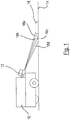
- a vehicle 10 which is preferably self-propelled, has an optoelectronic sensor device 12, which comprises a distance sensor aligned with a floor 14 ( Fig. 1 ).
- the distance sensor (not shown) is preferably integrated into the sensor device 12.
- an evaluation unit is provided which is connected to a control unit of the vehicle 10 (not shown).
- the distance sensor of the sensor device 12 determines distance information for four monitoring areas 16a, 16b, 16c, 16d, each of which covers an area of the floor 14.
- the distance information ascertained for each monitoring area 16a, 16b, 16c, 16d is compared with a respective expected floor area, an object and / or a floor anomaly being detected in the event of a deviation.
- an object 18 arranged on the floor 14 is detected by the monitoring areas 16a, 16b.
- the resultant change in the distance information means that the comparatively flat object 18 is reliably detected.
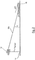
- FIG. 2 the geometry of the arrangement of the sensor device 12 relative to the floor 14 is illustrated, with FIG Fig. 2 only the monitoring area 16a is shown.
- the monitoring area 16a has an angle ⁇ with respect to the floor 14, which can be viewed as small.
- ⁇ R the change in distance caused by the object 18
- the object 18 can therefore be reliably recognized despite its small height.
- dR d ⁇ - cos ⁇ sin 2 ⁇ H sensor
- h sensor is the mounting height of the distance sensor, ie the orthogonal distance between the floor 14 and the distance sensor which is integrated in the sensor device 12.
- h sensor is the mounting height of the distance sensor, ie the orthogonal distance between the floor 14 and the distance sensor which is integrated in the sensor device 12.
- an optimal operating range of the sensor device 12 can be determined with regard to the parameters h sensor and ⁇ , which in principle can be freely selected and which indicate a reference position of the distance sensor relative to the floor 14.
- the floor 14 is a plane that functions as a reference floor.
- the corresponding cutting contours represent reference contours which, as described above, are used to determine expected Ground areas are used, such as the expected ground areas 28a, 28b, 28c, 28d of Fig. 4 .
- Fig. 3 shows a sensor board 20, which is mounted rotatably about an axis S and is a sensor head of the distance sensor of the sensor device 12.
- Four laser sensors 22a, 22b, 22c, 22d are arranged on the sensor board 20.
- the distance sensor can therefore also be referred to as a laser scanner.
- Each of the laser sensors 22a, 22b, 22c, 22d measures distances by means of laser beams 26, which are tilted relative to the sensor board 20 at a respective individual angle.
- Auxiliary lines 24 are drawn in, which are parallel to the plane of the sensor board 20.
- the tilt angles of the laser sensors 22a, 22b, 22c, 22d are +5, +2.5, 0 and -2.5 degrees.
- the sensor board 20 When used in the sensor device 12, the sensor board 20 is shown in FIG Fig. 1 and Fig. 2 inclined by the angle ⁇ relative to the floor 14 in order to form the monitoring areas 16a, 16b, 16c, 16d ( Fig. 1 ). It goes without saying that other distance sensors with other monitoring areas can also be provided.
- Fig. 4 four separate expected floor areas 28a, 28b, 28c, 28d are shown, which correspond to the floor areas that are covered by the monitoring areas 16a, 16b, 16c, 16d when the sensor board 20 from Fig. 3 is rotated and there is no object in the monitoring areas 16a, 16b, 16c, 16d.
- Fig. 4 thus represents a top view of the floor 14 (perspective perpendicular to the floor plane), the expected floor areas 28a, 28b, 28c, 28d being marked.
- distance points 30, 32 are determined by continuously periodic laser pulse measurements by means of the laser sensors 22a, 22b, 22c, 22d.
- the distance points 30 lie within the expected floor areas 28a, 28b, 28c, 28d, it can be assumed that the measurement of the distance points 30 emitted laser pulses hit the floor 14 unhindered (ie there is no object in the monitoring areas 16a, 16b, 16c, 16d) and the floor 14 has no floor anomaly (eg a depression). If, however, distance points 32 are measured that lie outside the expected floor areas 28a, 28b, 28c, 28d (or outside their tolerance areas), it can be assumed that an object or a floor anomaly is in the monitoring areas 16a, 16b, 16c, 16d is located, ie the distance points 32 are not assigned to the floor 14.
- Fig. 4 If the distance points 32 fall below the expected floor areas 28a and 28b. This corresponds to Fig. 1 , in which the object 18 is detected by the monitoring areas 16a and 16b and the distance points 32 lying on the object 18 have reduced distances from the sensor device 12 which are outside the expected floor areas 28a and 28b.
Landscapes
- Physics & Mathematics (AREA)
- Engineering & Computer Science (AREA)
- Electromagnetism (AREA)
- Computer Networks & Wireless Communication (AREA)
- General Physics & Mathematics (AREA)
- Radar, Positioning & Navigation (AREA)
- Remote Sensing (AREA)
- Length Measuring Devices By Optical Means (AREA)
- Optical Radar Systems And Details Thereof (AREA)
- Control Of Position, Course, Altitude, Or Attitude Of Moving Bodies (AREA)
Claims (15)
- Dispositif capteur optoélectronique (12) comportant un capteur de distance orienté vers un sol (14), qui détermine des informations de distance pour au moins une zone à surveiller (16a, 16b, 16c, 16d), ladite au moins une zone à surveiller (16a, 16b, 16c, 16d) recouvrant une zone de sol qui constitue une zone de surface du sol (14),
une unité d'évaluation réalisée pour reconnaître, sur la base des informations de distance, une déviation par rapport à au moins une zone de sol attendue (28a, 28b, 28c, 28d), et pour émettre un signal, en particulier un signal d'avertissement, lorsqu'une déviation est reconnue ;
caractérisé en ce que
ladite au moins une zone de sol attendue (28a, 28b, 28c, 28d) est basée sur un modèle prédéfini qui représente les informations de distance pour ladite au moins une zone à surveiller (16a, 16b, 16c, 16d) pour le cas théorique dans lequel le capteur de distance se situe dans une position de référence connue et est orienté vers un sol de référence connu ;
le capteur de distance étant réalisé sous forme de scanner laser multi-couche ayant une tête de scannage pouvant tourner autour d'un axe (S) incliné d'un angle (α) par rapport au sol et comprenant plusieurs capteurs lasers (22a, 22b, 22c, 22d) basculés les uns par rapport aux autres, dont l'un au moins comprend une zone à surveiller ayant une extension spatialement incurvée. - Dispositif capteur optoélectronique selon la revendication 1,
dans lequel le modèle est un modèle géométrique qui ne dépend pas des informations de distance déterminées par le capteur de distance lors un fonctionnement réel du dispositif capteur optoélectronique (12). - Dispositif capteur optoélectronique selon la revendication 1 ou 2,
dans lequel ladite au moins une zone à surveiller (16a, 16b, 16c, 16d) et le sol définissent un angle α qui est inférieur à quarante, de préférence inférieur à trente degrés. - Dispositif capteur optoélectronique selon l'une des revendications précédentes,
dans lequel le modèle comprend au moins un contour de distance de référence basé sur la position de référence et sur le sol de référence, et ladite au moins une zone de sol attendue (28a, 28b, 28c, 28d) forme une plage de tolérance autour dudit au moins un contour de distance de référence. - Dispositif capteur optoélectronique selon la revendication 4,
dans lequel ladite au moins une zone à surveiller présente une surface incurvée qui coupe au moins partiellement le sol de référence, la ligne d'intersection entre la surface et le sol de référence constituant ledit au moins un contour de distance de référence. - Dispositif capteur optoélectronique selon l'une des revendications précédentes,
dans lequel l'unité d'évaluation est réalisée pour définir ladite au moins une zone de sol attendue sur la base du modèle prédéfini. - Dispositif capteur optoélectronique selon l'une des revendications précédentes,
dans lequel l'unité d'évaluation est réalisée pour adapter ladite au moins une zone de sol attendue (28a, 28b, 28c, 28d) en fonction des informations de distance actuellement déterminées. - Dispositif capteur optoélectronique selon la revendication 7,
dans lequel les informations de distance déterminées incluent plusieurs points de distance (30, 32), l'unité d'évaluation étant réalisée pour adapter la zone de sol attendue (28a, 28b, 28c, 28d) en fonction d'un sous-ensemble desdits plusieurs points de distance, le sous-ensemble desdits plusieurs points de distance incluant des points de distance (30, 32) des informations de distance déterminées qui- se situent à l'intérieur de ladite au moins une zone de sol attendue (28a, 28b, 28c, 28d)
et/ou- se situent à l'intérieur d'une plage de tolérance autour d'un contour de distance de référence du modèle prédéfini,
et/ou- ne dépassent pas une première distance maximale prédéfinie,
et/ou- ne dépassent pas une seconde distance maximale prédéfinie par rapport à un point de distance voisin. - Dispositif capteur optoélectronique selon l'une des revendications précédentes,
dans lequel le capteur de distance détermine des informations de distance pour deux à six, de préférence quatre, zones à surveiller (16a, 16b, 16c, 16d), chacune des zones à surveiller (16a, 16b, 16c, 16d) recouvrant une zone de sol respective qui constitue une zone de surface du sol(14), les zones de sol recouvertes étant de préférence espacées les unes des autres. - Dispositif de capteur optoélectronique selon l'une des revendications précédentes,
dans lequel l'unité d'évaluation est adaptée pour déterminer une position du capteur de distance. - Dispositif capteur optoélectronique selon l'une des revendications précédentes,
dans lequel l'unité d'évaluation est un dispositif de calcul du capteur de distance, le traitement des données du capteur de distance ayant lieu entièrement ou partiellement dans le capteur de distance. - Véhicule (12) comportant
un dispositif capteur optoélectronique (12) selon l'une des revendications précédentes, et
une unité de commande,
une unité d'évaluation réalisée pour reconnaître, sur la base des informations de distance, une déviation par rapport à au moins une zone de sol attendue (28a, 28b, 28c, 28d), et pour émettre un signal, en particulier un signal d'avertissement, à l'unité de commande lorsqu'une déviation est reconnue. - Véhicule (12) selon la revendication 12,
dans lequel l'unité d'évaluation est réalisée pour adapter le modèle prédéfini aux mouvements du véhicule (12) qui dépendent de l'accélération. - Véhicule (12) selon la revendication 9 ou 10,
dans lequel le véhicule (12) est automoteur. - Procédé de fonctionnement d'un dispositif capteur optoélectronique (12), dans lequel
des informations de distance pour au moins une zone à surveiller (16a, 16b, 16c, 16d) sont déterminées à l'aide d'un capteur de distance orienté vers un sol (14), ladite au moins une zone à surveiller (16a, 16b, 16c, 16d) recouvrant une zone de sol qui constitue une zone de surface du sol (14),
une déviation par rapport à au moins une zone de sol attendue (28a, 28b, 28c, 28d) est reconnue sur la base des informations de distance à l'aide d'une unité d'évaluation, et un signal, en particulier un signal d'avertissement, est émis lorsqu'une déviation est reconnue ;
caractérisé en ce que
ladite au moins une zone de sol attendue (28a, 28b, 28c, 28d) est basée sur un modèle prédéfini qui représente les informations de distance pour ladite au moins une zone à surveiller (16a, 16b, 16c, 16d) pour le cas théorique dans lequel le capteur de distance se situe dans une position de référence connue et est orienté vers un sol de référence connu ;
le capteur de distance étant réalisé sous forme de scanner laser multi-couche ayant une tête de scannage pouvant tourner autour d'un axe (S) incliné d'un angle (α) par rapport au sol et comprenant plusieurs capteurs lasers (22a, 22b, 22c, 22d) basculés les uns par rapport aux autres, dont l'un au moins comprend une zone à surveiller ayant une extension spatialement incurvée.
Applications Claiming Priority (1)
| Application Number | Priority Date | Filing Date | Title |
|---|---|---|---|
| DE102018102287.5A DE102018102287A1 (de) | 2018-02-01 | 2018-02-01 | Optoelektronische Sensorvorrichtung |
Publications (2)
| Publication Number | Publication Date |
|---|---|
| EP3521860A1 EP3521860A1 (fr) | 2019-08-07 |
| EP3521860B1 true EP3521860B1 (fr) | 2020-12-16 |
Family
ID=65013582
Family Applications (1)
| Application Number | Title | Priority Date | Filing Date |
|---|---|---|---|
| EP19151190.6A Active EP3521860B1 (fr) | 2018-02-01 | 2019-01-10 | Dispositif capteur optoélectronique |
Country Status (2)
| Country | Link |
|---|---|
| EP (1) | EP3521860B1 (fr) |
| DE (1) | DE102018102287A1 (fr) |
Cited By (1)
| Publication number | Priority date | Publication date | Assignee | Title |
|---|---|---|---|---|
| EP4401045A1 (fr) | 2023-01-10 | 2024-07-17 | Sick Ag | Configuration de capteur 3d pour un suivi d'objet sécurisé |
Families Citing this family (2)
| Publication number | Priority date | Publication date | Assignee | Title |
|---|---|---|---|---|
| DE102019217988A1 (de) * | 2019-11-21 | 2021-05-27 | Zf Friedrichshafen Ag | Kamerabasierte Detektion von Kippbewegungen |
| EP4109127B1 (fr) | 2021-06-21 | 2023-05-10 | Sick Ag | Capteur optoélectronique et procédé de détection des objets |
Family Cites Families (5)
| Publication number | Priority date | Publication date | Assignee | Title |
|---|---|---|---|---|
| US7741961B1 (en) * | 2006-09-29 | 2010-06-22 | Canesta, Inc. | Enhanced obstacle detection and tracking for three-dimensional imaging systems used in motor vehicles |
| AT507586B1 (de) * | 2008-11-27 | 2011-09-15 | Ds Automotion Gmbh | Vorrichtung und verfahren zur optischen lagebestimmung |
| DE102011080932A1 (de) * | 2011-08-12 | 2013-02-14 | Robert Bosch Gmbh | Verfahren zur Unterstützung eines Fahrers eines Fahrzeuges |
| DE102013207147A1 (de) * | 2012-05-03 | 2013-11-07 | Ifm Electronic Gmbh | System und Verfahren zur Erfassung eines Fahrbahnprofils |
| DE102014217352B4 (de) * | 2014-08-29 | 2018-04-19 | HAP Handhabungs-, Automatisierungs- und Präzisionstechnik GmbH | Verfahrbare Vorrichtung zur Manipulation von Gegenständen |
-
2018
- 2018-02-01 DE DE102018102287.5A patent/DE102018102287A1/de not_active Withdrawn
-
2019
- 2019-01-10 EP EP19151190.6A patent/EP3521860B1/fr active Active
Non-Patent Citations (1)
| Title |
|---|
| None * |
Cited By (2)
| Publication number | Priority date | Publication date | Assignee | Title |
|---|---|---|---|---|
| EP4401045A1 (fr) | 2023-01-10 | 2024-07-17 | Sick Ag | Configuration de capteur 3d pour un suivi d'objet sécurisé |
| US12469174B2 (en) | 2023-01-10 | 2025-11-11 | Sick Ag | Configuration of a 3D sensor for safe object tracking |
Also Published As
| Publication number | Publication date |
|---|---|
| DE102018102287A1 (de) | 2019-08-01 |
| EP3521860A1 (fr) | 2019-08-07 |
Similar Documents
| Publication | Publication Date | Title |
|---|---|---|
| EP2339376B1 (fr) | Capteur optoélectronique | |
| DE10141294B4 (de) | Verfahren zur Bodenerkennung | |
| EP1643271B1 (fr) | Procédé et dispositif pour classifier des limites latéraux d'une place de stationnement pour un système d'assistance au stationnement d'un véhicule automobile | |
| EP3521860B1 (fr) | Dispositif capteur optoélectronique | |
| DE102008032216A1 (de) | Vorrichtung zur Erkennung der Anwesenheit eines Objekts im Raum | |
| DE102015213694A1 (de) | Sensorsystem zum Erkennen überstehender oder freiliegender Objekte in der Umgebung eines Fahrzeugs | |
| WO2014079697A1 (fr) | Dispositif et véhicule à compensation d'inclinaison d'un capteur d'environnement | |
| EP3791105B1 (fr) | Dispositif et procédé pour sécuriser un appareil mobile à commande mécanique ou automatique et carreau de capteurs | |
| EP1224644B1 (fr) | Dispositif pour reguler le flux de circulation a un carrefour, notamment pour reguler les feux | |
| WO2004019293A2 (fr) | Surveillance de l'environnement d'un objet | |
| DE102017124962B4 (de) | Vermeidung von falschen Objekterfassungen bei Hindernissen oberhalb eines Fahrzeugs | |
| EP2395372B1 (fr) | Scanner de sécurité | |
| EP3738420B1 (fr) | Procédé de fonctionnement d'un engin agricole automatique | |
| DE102021112709B4 (de) | LiDAR Laser-Scanner | |
| WO2016075306A1 (fr) | Procédé de limitation de la hauteur de levage et/ou de l'angle de pivotement d'un excavateur | |
| WO2020260242A1 (fr) | Détermination d'un angle de tangage d'un système de détection optique actif | |
| DE102011000514A1 (de) | Automatische Türschwenkvorrichtung | |
| WO2020207762A1 (fr) | Automatisation d'un véhicule hors route | |
| EP3710905B1 (fr) | Système d'infrastructure | |
| EP0907805B1 (fr) | Procede et dispositif de surveillance de la zone de travail lors du deplacement d'un engin de travaux | |
| EP3788406B1 (fr) | Procédé permettant de déterminer une orientation d'un capteur optoélectronique au moyen de points de balayage d'une image du capteur et capteur optoélectronique | |
| EP1125176B1 (fr) | Systeme mobile autonome anti-chute a reperes de zone | |
| WO2024115657A1 (fr) | Dispositif de sécurité pour sécuriser une zone dangereuse d'une machine fonctionnant de manière automatisée, en particulier un robot | |
| EP3699634B1 (fr) | Module de capteur | |
| EP3913179A1 (fr) | Installation automatique de fenêtre ou de porte |
Legal Events
| Date | Code | Title | Description |
|---|---|---|---|
| PUAI | Public reference made under article 153(3) epc to a published international application that has entered the european phase |
Free format text: ORIGINAL CODE: 0009012 |
|
| STAA | Information on the status of an ep patent application or granted ep patent |
Free format text: STATUS: THE APPLICATION HAS BEEN PUBLISHED |
|
| AK | Designated contracting states |
Kind code of ref document: A1 Designated state(s): AL AT BE BG CH CY CZ DE DK EE ES FI FR GB GR HR HU IE IS IT LI LT LU LV MC MK MT NL NO PL PT RO RS SE SI SK SM TR |
|
| AX | Request for extension of the european patent |
Extension state: BA ME |
|
| STAA | Information on the status of an ep patent application or granted ep patent |
Free format text: STATUS: REQUEST FOR EXAMINATION WAS MADE |
|
| RAP1 | Party data changed (applicant data changed or rights of an application transferred) |
Owner name: SICK AG |
|
| 17P | Request for examination filed |
Effective date: 20200204 |
|
| RBV | Designated contracting states (corrected) |
Designated state(s): AL AT BE BG CH CY CZ DE DK EE ES FI FR GB GR HR HU IE IS IT LI LT LU LV MC MK MT NL NO PL PT RO RS SE SI SK SM TR |
|
| STAA | Information on the status of an ep patent application or granted ep patent |
Free format text: STATUS: EXAMINATION IS IN PROGRESS |
|
| 17Q | First examination report despatched |
Effective date: 20200326 |
|
| REG | Reference to a national code |
Ref country code: DE Ref legal event code: R079 Ref document number: 502019000513 Country of ref document: DE Free format text: PREVIOUS MAIN CLASS: G01S0017930000 Ipc: G01S0017420000 |
|
| GRAP | Despatch of communication of intention to grant a patent |
Free format text: ORIGINAL CODE: EPIDOSNIGR1 |
|
| STAA | Information on the status of an ep patent application or granted ep patent |
Free format text: STATUS: GRANT OF PATENT IS INTENDED |
|
| GRAJ | Information related to disapproval of communication of intention to grant by the applicant or resumption of examination proceedings by the epo deleted |
Free format text: ORIGINAL CODE: EPIDOSDIGR1 |
|
| RIC1 | Information provided on ipc code assigned before grant |
Ipc: G01S 17/931 20200101ALI20200608BHEP Ipc: G01S 17/87 20200101ALI20200608BHEP Ipc: G01S 7/48 20060101ALI20200608BHEP Ipc: G01S 17/42 20060101AFI20200608BHEP |
|
| STAA | Information on the status of an ep patent application or granted ep patent |
Free format text: STATUS: EXAMINATION IS IN PROGRESS |
|
| INTG | Intention to grant announced |
Effective date: 20200703 |
|
| GRAP | Despatch of communication of intention to grant a patent |
Free format text: ORIGINAL CODE: EPIDOSNIGR1 |
|
| STAA | Information on the status of an ep patent application or granted ep patent |
Free format text: STATUS: GRANT OF PATENT IS INTENDED |
|
| INTC | Intention to grant announced (deleted) | ||
| INTG | Intention to grant announced |
Effective date: 20200817 |
|
| GRAS | Grant fee paid |
Free format text: ORIGINAL CODE: EPIDOSNIGR3 |
|
| GRAA | (expected) grant |
Free format text: ORIGINAL CODE: 0009210 |
|
| STAA | Information on the status of an ep patent application or granted ep patent |
Free format text: STATUS: THE PATENT HAS BEEN GRANTED |
|
| AK | Designated contracting states |
Kind code of ref document: B1 Designated state(s): AL AT BE BG CH CY CZ DE DK EE ES FI FR GB GR HR HU IE IS IT LI LT LU LV MC MK MT NL NO PL PT RO RS SE SI SK SM TR |
|
| REG | Reference to a national code |
Ref country code: GB Ref legal event code: FG4D Free format text: NOT ENGLISH |
|
| REG | Reference to a national code |
Ref country code: DE Ref legal event code: R096 Ref document number: 502019000513 Country of ref document: DE |
|
| REG | Reference to a national code |
Ref country code: IE Ref legal event code: FG4D Free format text: LANGUAGE OF EP DOCUMENT: GERMAN |
|
| REG | Reference to a national code |
Ref country code: AT Ref legal event code: REF Ref document number: 1346099 Country of ref document: AT Kind code of ref document: T Effective date: 20210115 |
|
| PG25 | Lapsed in a contracting state [announced via postgrant information from national office to epo] |
Ref country code: NO Free format text: LAPSE BECAUSE OF FAILURE TO SUBMIT A TRANSLATION OF THE DESCRIPTION OR TO PAY THE FEE WITHIN THE PRESCRIBED TIME-LIMIT Effective date: 20210316 Ref country code: GR Free format text: LAPSE BECAUSE OF FAILURE TO SUBMIT A TRANSLATION OF THE DESCRIPTION OR TO PAY THE FEE WITHIN THE PRESCRIBED TIME-LIMIT Effective date: 20210317 Ref country code: RS Free format text: LAPSE BECAUSE OF FAILURE TO SUBMIT A TRANSLATION OF THE DESCRIPTION OR TO PAY THE FEE WITHIN THE PRESCRIBED TIME-LIMIT Effective date: 20201216 Ref country code: FI Free format text: LAPSE BECAUSE OF FAILURE TO SUBMIT A TRANSLATION OF THE DESCRIPTION OR TO PAY THE FEE WITHIN THE PRESCRIBED TIME-LIMIT Effective date: 20201216 |
|
| REG | Reference to a national code |
Ref country code: NL Ref legal event code: MP Effective date: 20201216 |
|
| PG25 | Lapsed in a contracting state [announced via postgrant information from national office to epo] |
Ref country code: SE Free format text: LAPSE BECAUSE OF FAILURE TO SUBMIT A TRANSLATION OF THE DESCRIPTION OR TO PAY THE FEE WITHIN THE PRESCRIBED TIME-LIMIT Effective date: 20201216 Ref country code: LV Free format text: LAPSE BECAUSE OF FAILURE TO SUBMIT A TRANSLATION OF THE DESCRIPTION OR TO PAY THE FEE WITHIN THE PRESCRIBED TIME-LIMIT Effective date: 20201216 Ref country code: BG Free format text: LAPSE BECAUSE OF FAILURE TO SUBMIT A TRANSLATION OF THE DESCRIPTION OR TO PAY THE FEE WITHIN THE PRESCRIBED TIME-LIMIT Effective date: 20210316 |
|
| PG25 | Lapsed in a contracting state [announced via postgrant information from national office to epo] |
Ref country code: NL Free format text: LAPSE BECAUSE OF FAILURE TO SUBMIT A TRANSLATION OF THE DESCRIPTION OR TO PAY THE FEE WITHIN THE PRESCRIBED TIME-LIMIT Effective date: 20201216 Ref country code: HR Free format text: LAPSE BECAUSE OF FAILURE TO SUBMIT A TRANSLATION OF THE DESCRIPTION OR TO PAY THE FEE WITHIN THE PRESCRIBED TIME-LIMIT Effective date: 20201216 |
|
| REG | Reference to a national code |
Ref country code: LT Ref legal event code: MG9D |
|
| PG25 | Lapsed in a contracting state [announced via postgrant information from national office to epo] |
Ref country code: EE Free format text: LAPSE BECAUSE OF FAILURE TO SUBMIT A TRANSLATION OF THE DESCRIPTION OR TO PAY THE FEE WITHIN THE PRESCRIBED TIME-LIMIT Effective date: 20201216 Ref country code: CZ Free format text: LAPSE BECAUSE OF FAILURE TO SUBMIT A TRANSLATION OF THE DESCRIPTION OR TO PAY THE FEE WITHIN THE PRESCRIBED TIME-LIMIT Effective date: 20201216 Ref country code: SK Free format text: LAPSE BECAUSE OF FAILURE TO SUBMIT A TRANSLATION OF THE DESCRIPTION OR TO PAY THE FEE WITHIN THE PRESCRIBED TIME-LIMIT Effective date: 20201216 Ref country code: SM Free format text: LAPSE BECAUSE OF FAILURE TO SUBMIT A TRANSLATION OF THE DESCRIPTION OR TO PAY THE FEE WITHIN THE PRESCRIBED TIME-LIMIT Effective date: 20201216 Ref country code: LT Free format text: LAPSE BECAUSE OF FAILURE TO SUBMIT A TRANSLATION OF THE DESCRIPTION OR TO PAY THE FEE WITHIN THE PRESCRIBED TIME-LIMIT Effective date: 20201216 Ref country code: PT Free format text: LAPSE BECAUSE OF FAILURE TO SUBMIT A TRANSLATION OF THE DESCRIPTION OR TO PAY THE FEE WITHIN THE PRESCRIBED TIME-LIMIT Effective date: 20210416 Ref country code: RO Free format text: LAPSE BECAUSE OF FAILURE TO SUBMIT A TRANSLATION OF THE DESCRIPTION OR TO PAY THE FEE WITHIN THE PRESCRIBED TIME-LIMIT Effective date: 20201216 |
|
| PG25 | Lapsed in a contracting state [announced via postgrant information from national office to epo] |
Ref country code: PL Free format text: LAPSE BECAUSE OF FAILURE TO SUBMIT A TRANSLATION OF THE DESCRIPTION OR TO PAY THE FEE WITHIN THE PRESCRIBED TIME-LIMIT Effective date: 20201216 |
|
| REG | Reference to a national code |
Ref country code: DE Ref legal event code: R097 Ref document number: 502019000513 Country of ref document: DE |
|
| PG25 | Lapsed in a contracting state [announced via postgrant information from national office to epo] |
Ref country code: IS Free format text: LAPSE BECAUSE OF FAILURE TO SUBMIT A TRANSLATION OF THE DESCRIPTION OR TO PAY THE FEE WITHIN THE PRESCRIBED TIME-LIMIT Effective date: 20210416 Ref country code: MC Free format text: LAPSE BECAUSE OF FAILURE TO SUBMIT A TRANSLATION OF THE DESCRIPTION OR TO PAY THE FEE WITHIN THE PRESCRIBED TIME-LIMIT Effective date: 20201216 Ref country code: LU Free format text: LAPSE BECAUSE OF NON-PAYMENT OF DUE FEES Effective date: 20210110 |
|
| REG | Reference to a national code |
Ref country code: BE Ref legal event code: MM Effective date: 20210131 |
|
| PLBE | No opposition filed within time limit |
Free format text: ORIGINAL CODE: 0009261 |
|
| STAA | Information on the status of an ep patent application or granted ep patent |
Free format text: STATUS: NO OPPOSITION FILED WITHIN TIME LIMIT |
|
| PG25 | Lapsed in a contracting state [announced via postgrant information from national office to epo] |
Ref country code: AL Free format text: LAPSE BECAUSE OF FAILURE TO SUBMIT A TRANSLATION OF THE DESCRIPTION OR TO PAY THE FEE WITHIN THE PRESCRIBED TIME-LIMIT Effective date: 20201216 Ref country code: IT Free format text: LAPSE BECAUSE OF FAILURE TO SUBMIT A TRANSLATION OF THE DESCRIPTION OR TO PAY THE FEE WITHIN THE PRESCRIBED TIME-LIMIT Effective date: 20201216 |
|
| 26N | No opposition filed |
Effective date: 20210917 |
|
| PG25 | Lapsed in a contracting state [announced via postgrant information from national office to epo] |
Ref country code: DK Free format text: LAPSE BECAUSE OF FAILURE TO SUBMIT A TRANSLATION OF THE DESCRIPTION OR TO PAY THE FEE WITHIN THE PRESCRIBED TIME-LIMIT Effective date: 20201216 |
|
| PG25 | Lapsed in a contracting state [announced via postgrant information from national office to epo] |
Ref country code: IE Free format text: LAPSE BECAUSE OF NON-PAYMENT OF DUE FEES Effective date: 20210110 Ref country code: ES Free format text: LAPSE BECAUSE OF FAILURE TO SUBMIT A TRANSLATION OF THE DESCRIPTION OR TO PAY THE FEE WITHIN THE PRESCRIBED TIME-LIMIT Effective date: 20201216 |
|
| PG25 | Lapsed in a contracting state [announced via postgrant information from national office to epo] |
Ref country code: SI Free format text: LAPSE BECAUSE OF FAILURE TO SUBMIT A TRANSLATION OF THE DESCRIPTION OR TO PAY THE FEE WITHIN THE PRESCRIBED TIME-LIMIT Effective date: 20201216 |
|
| PG25 | Lapsed in a contracting state [announced via postgrant information from national office to epo] |
Ref country code: IS Free format text: LAPSE BECAUSE OF FAILURE TO SUBMIT A TRANSLATION OF THE DESCRIPTION OR TO PAY THE FEE WITHIN THE PRESCRIBED TIME-LIMIT Effective date: 20210416 |
|
| PG25 | Lapsed in a contracting state [announced via postgrant information from national office to epo] |
Ref country code: BE Free format text: LAPSE BECAUSE OF NON-PAYMENT OF DUE FEES Effective date: 20210131 |
|
| REG | Reference to a national code |
Ref country code: CH Ref legal event code: PL |
|
| PG25 | Lapsed in a contracting state [announced via postgrant information from national office to epo] |
Ref country code: LI Free format text: LAPSE BECAUSE OF NON-PAYMENT OF DUE FEES Effective date: 20220131 Ref country code: CH Free format text: LAPSE BECAUSE OF NON-PAYMENT OF DUE FEES Effective date: 20220131 |
|
| PG25 | Lapsed in a contracting state [announced via postgrant information from national office to epo] |
Ref country code: CY Free format text: LAPSE BECAUSE OF FAILURE TO SUBMIT A TRANSLATION OF THE DESCRIPTION OR TO PAY THE FEE WITHIN THE PRESCRIBED TIME-LIMIT Effective date: 20201216 |
|
| PG25 | Lapsed in a contracting state [announced via postgrant information from national office to epo] |
Ref country code: HU Free format text: LAPSE BECAUSE OF FAILURE TO SUBMIT A TRANSLATION OF THE DESCRIPTION OR TO PAY THE FEE WITHIN THE PRESCRIBED TIME-LIMIT; INVALID AB INITIO Effective date: 20190110 |
|
| GBPC | Gb: european patent ceased through non-payment of renewal fee |
Effective date: 20230110 |
|
| PG25 | Lapsed in a contracting state [announced via postgrant information from national office to epo] |
Ref country code: GB Free format text: LAPSE BECAUSE OF NON-PAYMENT OF DUE FEES Effective date: 20230110 |
|
| PG25 | Lapsed in a contracting state [announced via postgrant information from national office to epo] |
Ref country code: MK Free format text: LAPSE BECAUSE OF FAILURE TO SUBMIT A TRANSLATION OF THE DESCRIPTION OR TO PAY THE FEE WITHIN THE PRESCRIBED TIME-LIMIT Effective date: 20201216 |
|
| PG25 | Lapsed in a contracting state [announced via postgrant information from national office to epo] |
Ref country code: TR Free format text: LAPSE BECAUSE OF FAILURE TO SUBMIT A TRANSLATION OF THE DESCRIPTION OR TO PAY THE FEE WITHIN THE PRESCRIBED TIME-LIMIT Effective date: 20201216 |
|
| PG25 | Lapsed in a contracting state [announced via postgrant information from national office to epo] |
Ref country code: MT Free format text: LAPSE BECAUSE OF FAILURE TO SUBMIT A TRANSLATION OF THE DESCRIPTION OR TO PAY THE FEE WITHIN THE PRESCRIBED TIME-LIMIT Effective date: 20201216 |
|
| REG | Reference to a national code |
Ref country code: AT Ref legal event code: MM01 Ref document number: 1346099 Country of ref document: AT Kind code of ref document: T Effective date: 20240110 |
|
| PG25 | Lapsed in a contracting state [announced via postgrant information from national office to epo] |
Ref country code: AT Free format text: LAPSE BECAUSE OF NON-PAYMENT OF DUE FEES Effective date: 20240110 |
|
| PGFP | Annual fee paid to national office [announced via postgrant information from national office to epo] |
Ref country code: DE Payment date: 20260120 Year of fee payment: 8 |
|
| PGFP | Annual fee paid to national office [announced via postgrant information from national office to epo] |
Ref country code: AT Payment date: 20260410 Year of fee payment: 5 |
|
| PGFP | Annual fee paid to national office [announced via postgrant information from national office to epo] |
Ref country code: FR Payment date: 20260128 Year of fee payment: 8 |