EP1238897A2 - Raupenfahrzeug mit oszillierenden Gleiskettenlaufwerken - Google Patents
Raupenfahrzeug mit oszillierenden Gleiskettenlaufwerken Download PDFInfo
- Publication number
- EP1238897A2 EP1238897A2 EP02075603A EP02075603A EP1238897A2 EP 1238897 A2 EP1238897 A2 EP 1238897A2 EP 02075603 A EP02075603 A EP 02075603A EP 02075603 A EP02075603 A EP 02075603A EP 1238897 A2 EP1238897 A2 EP 1238897A2
- Authority
- EP
- European Patent Office
- Prior art keywords
- carriage
- vehicle according
- cross member
- hinge axis
- eccentric portion
- Prior art date
- Legal status (The legal status is an assumption and is not a legal conclusion. Google has not performed a legal analysis and makes no representation as to the accuracy of the status listed.)
- Granted
Links
- 230000010355 oscillation Effects 0.000 claims abstract description 6
- 230000001419 dependent effect Effects 0.000 claims 1
- 230000000712 assembly Effects 0.000 description 6
- 238000000429 assembly Methods 0.000 description 6
- 239000000428 dust Substances 0.000 description 2
- 230000000717 retained effect Effects 0.000 description 2
- 230000006978 adaptation Effects 0.000 description 1
- 238000005452 bending Methods 0.000 description 1
- 239000003795 chemical substances by application Substances 0.000 description 1
- 238000012423 maintenance Methods 0.000 description 1
- 239000011435 rock Substances 0.000 description 1
- 239000000725 suspension Substances 0.000 description 1
Images

Classifications
-
- B—PERFORMING OPERATIONS; TRANSPORTING
- B62—LAND VEHICLES FOR TRAVELLING OTHERWISE THAN ON RAILS
- B62D—MOTOR VEHICLES; TRAILERS
- B62D55/00—Endless track vehicles
- B62D55/08—Endless track units; Parts thereof
- B62D55/084—Endless-track units or carriages mounted separably, adjustably or extensibly on vehicles, e.g. portable track units
- B62D55/0842—Tracked vehicle with track carriages suspended on three points, e.g. by an equaliser bar
Definitions
- the present invention relates to a crawler vehicle with oscillating track carriages, which is normally used as an earth-moving machine, in particular as a bulldozer. More specifically, the present invention relates to a vehicle having a longitudinal axis, a supporting frame, and two longitudinal carriages located on opposite sides of the frame. The carriages support respective tracks for driving the vehicle, and are connected to the frame by respective rear pivots to rotate about a rear transverse axis and in a substantially vertical oscillating plane in dependence of the roughness of the ground over which the vehicle travels.
- each carriage commonly is connected to the frame by a vertical guide for guiding the movement of the carriage in the oscillating plane.
- the front ends of the carriages are connected to each other by a front cross member, a central portion of which is hinged to the vehicle frame to rotate about a hinge axis parallel to the longitudinal axis. More specifically, each end of the cross member is hinged to the respective carriage by a cylindrical hinge pin perpendicular to the rear transverse axis.
- a crawler vehicle having :
- the crawler vehicle is characterized in that it further comprises compensating means for varying the length of said cross member between two given values as said carriages oscillate about said first hinge axis.
- Reference number 1 in Figure 1 indicates a crawler vehicle normally used as an earth-moving machine and, in particular, as a bulldozer.
- Vehicle 1 has a longitudinal central axis 3, and comprises a supporting frame 2 extending in the direction 3.
- Vehicle 1 further comprises two track carriages 4 located on opposite sides of frame 2 and extending in directions substantially parallel to the axis 3.
- each carriage 4 comprises a supporting structure 6 and a track 7, which is supported by and runs along the periphery of structure 6.
- Each track 7 is powered in known manner (not shown) to propel vehicle 1.
- Structures 6 comprise respective rear portions 8 connected to frame 2 by respective connecting assemblies 9 (not described in detail, and only one of which is shown in Figure 1) enabling carriages 4 to oscillate, with respect to frame 2, about a horizontal hinge axis 10 perpendicular to direction 3, and on opposite sides of an intermediate reference position in which the carriages 4 are parallel to each other.
- Assemblies 9 allow a certain radial and axial clearance in the connection of rear portions 8 to frame 2.
- structures 6 also comprise respective front connecting forks 12, each of which comprises two arms 13, 14 facing frame 2 and defining respective cylindrical seats 15, 16 formed along a relative axis 17 perpendicular to axis 10.
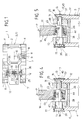
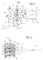
- Structures 6 are connected to each other and supported by a front suspension defined by a cross member 18, which is substantially parallel to axis 10 and, in turn, comprises a central portion 19 connected to frame 2 by a known hinge device 20 (Figure 1) to allow cross member 18 to oscillate about a central axis 21 parallel to direction 3, and in a vertical plane P perpendicular to axis 21 ( Figure 3) and coincident with the Figure 2 plane.
- a cross member 18 which is substantially parallel to axis 10 and, in turn, comprises a central portion 19 connected to frame 2 by a known hinge device 20 (Figure 1) to allow cross member 18 to oscillate about a central axis 21 parallel to direction 3, and in a vertical plane P perpendicular to axis 21 ( Figure 3) and coincident with the Figure 2 plane.
- Cross member 18 comprises two opposite arms 22, each terminating with a portion 23, which is interposed between arms 13, 14 of a respective fork 12 and is connected to fork 12 by a connecting assembly 25 comprising seats 15, 16, a longitudinal seat 26 formed through portion 23 ( Figures 4 and 5), and a hinge pin 30 engaging seats 15, 26 and 16.
- pin 30 comprises two coaxial, opposite cylindrical end portions 36, 37, which engage respective seats 15 and 16 along axis 17 in axially-fixed, rotary manner to permit relative oscillation of cross member 18 and each carriage 4.
- Pin 30 further comprises a cylindrical intermediate portion 38, which extends between portions 36 and 37 along a respective axis 40 parallel to and offset with respect to axis 17.
- Portion 38 has a diameter between those of portions 36, 37, and has two diametrically opposite generating lines defining extensions of a respective upper generating line of portion 36 and a lower generating line of portion 37, with respect to the view of Figure 4.
- Portion 38 engages seat 26 and is connected to portion 23 by the interposition of an articulated or spherical joint 44 forming part of assembly 25 and comprising an outer ring 45 connected integrally to portion 23 and defining a spherical seat 46; and an inner ring 47, connected to portion 38, which is able to slide axially in opposite directions ( Figure 3) and comprising a spherical head 48 engaging seat 46.
- carriages 4 With reference to Figures 1 to 5, in actual use, the position of carriages 4 with respect to frame 2 adapts automatically in dependence of the roughness of the terrain.
- carriages 4 When vehicle 1 travels over flat ground, carriages 4 remain in the intermediate reference position ( Figure 5 and the parts shown by the continuous lines in Figure 2), and each pin 30 is set to a first operating position in which respective axes 17 and 40 are parallel to axis 21 and lie in a plane Q perpendicular to axis 10 and parallel to the oscillating planes of carriages 4.
- carriages 4 Conversely, when vehicle 1 travels through a dip or over a bump, carriages 4 rotate in opposite directions about axis 10, so that cross member 18 rocks about axis 21 in plane P.
- axes 17 are retained by structures 6 to rotate about axis 10 in respective planes Q, while axes 40 are retained by cross member 18 and articulated joints 44 to rotate about axis 21.
- each pin 30 rotates in seats 15, 16 about respective axis 17 automatically so as to vary the length of cross member 18, i.e. the distance between axes 17.
- Each pin 30 is free to rotate from the first operating position ( Figures 2 and 5), in which cross member 18 is of a length of value L1 ( Figure 2), to a second limit operating position ( Figures 2 and 4), in which axes 17, 40 intersect the same line R, radial with respect to axis 21, and the length of cross member 18 takes up a value L2 greater than L1. More specifically, the difference between values L1 and L2 equals twice the eccentricity of portion 38.
- each articulated joint 44 adapts the tilt of respective pin 30 to that of cross member 18, while the sliding connection of inner ring 47 to portion 38 provides for guiding pin 30 axially and compensating for the difference D between the trajectories travelled by fork 12 and portion 23 along axis 17 ( Figure 3) as a carriage 4 oscillates.
- Figure 6 shows, schematically, a variation of assembly 25, in which inner ring 47 is connected integrally to portion 38 of the guiding pin 30, while arms 13, 14 define respective guiding seats 15, 16 along axis 17, and portions 36, 37 define respective slides connected in axially-sliding manner to arms 13, 14.
- the outer ring 45 connected integrally to the cross member 18 is enabled to remain in the plane P during pivotal movement of a carriage 4 around axis 10 by virtue of the sliding movement of the pin 30 inside the seats 15, 16.
- each carriage 4 to also oscillate about any axis crosswise to axis 10, and to adapt its lateral position, parallel to axis 10, by relatively small movements, but sufficient to further improve the ability of carriage 4 to adapt to the roughness of the terrain over which vehicle 1 travels.
- the position of carriages 4 with respect to frame 2 can therefore be adapted according to the roughness of the terrain without generating severe stress or strain on structures 6 or assemblies 9, 25.
- Assemblies 25, in fact, enable each carriage 4 to adapt its position with respect to cross member 18 in practically any direction in space.
- Such adaptation happens in a controlled, as opposed to random, manner, by means of articulated joint 44 and, in particular, by pin 30, the position of which is variable between two limit operating positions determined by the eccentricity of portion 38.
- Assembly 25 is also reliable in design, since the connection between forks 12 and pin 30 is protected in a relatively straightforward manner against external agents, such as dust.
- pin 30 can be assembled relatively easily in one operation, by inserting it axially inside seat 15, through inner ring 47, and into seat 16.
- compensating devices other than pins 30 may be provided to vary the length of cross member 18, and/or connecting assemblies other than articulated joint 44 may be interposed between portion 38 and end portion 23.
- articulated joint 44 may be carried by structure 6 as opposed to cross member 18, and pin 30 may be carried by a fork integral with cross member 18.
Landscapes
- Engineering & Computer Science (AREA)
- Chemical & Material Sciences (AREA)
- Combustion & Propulsion (AREA)
- Transportation (AREA)
- Mechanical Engineering (AREA)
- Body Structure For Vehicles (AREA)
- Non-Deflectable Wheels, Steering Of Trailers, Or Other Steering (AREA)
- Vehicle Body Suspensions (AREA)
Applications Claiming Priority (2)
| Application Number | Priority Date | Filing Date | Title |
|---|---|---|---|
| IT2001TO000216A ITTO20010216A1 (it) | 2001-03-09 | 2001-03-09 | Veicolo cingolato provvisto di carrelli cingolati oscillanti. |
| ITTO010216 | 2001-03-09 |
Publications (3)
| Publication Number | Publication Date |
|---|---|
| EP1238897A2 true EP1238897A2 (de) | 2002-09-11 |
| EP1238897A3 EP1238897A3 (de) | 2004-05-12 |
| EP1238897B1 EP1238897B1 (de) | 2007-01-17 |
Family
ID=11458670
Family Applications (1)
| Application Number | Title | Priority Date | Filing Date |
|---|---|---|---|
| EP02075603A Expired - Lifetime EP1238897B1 (de) | 2001-03-09 | 2002-02-14 | Raupenfahrzeug mit oszillierenden Gleiskettenlaufwerken |
Country Status (5)
| Country | Link |
|---|---|
| US (1) | US6823953B2 (de) |
| EP (1) | EP1238897B1 (de) |
| JP (1) | JP4175454B2 (de) |
| DE (1) | DE60217565T2 (de) |
| IT (1) | ITTO20010216A1 (de) |
Cited By (2)
| Publication number | Priority date | Publication date | Assignee | Title |
|---|---|---|---|---|
| WO2008043097A3 (en) * | 2006-10-06 | 2008-08-14 | Lord Corp | Vehicle with elastomeric bearing suspension system and elastomeric bearing therefor |
| WO2023002241A1 (en) * | 2021-07-21 | 2023-01-26 | Comacchio Srl | Tracked undercarriage for operating machines |
Families Citing this family (2)
| Publication number | Priority date | Publication date | Assignee | Title |
|---|---|---|---|---|
| US7516805B2 (en) * | 2005-12-20 | 2009-04-14 | Caterpillar Inc. | Equalizer bar mounting arrangement |
| IT201700032682A1 (it) * | 2017-03-24 | 2018-09-24 | Zona Eng & Design S A S Di Zona Mauro & C | Veicolo atv ad alta mobilita', utilizzabile ad esempio in attivita' civili di emergenza e soccorso, in campo agricolo o in attivita' di movimento terra |
Family Cites Families (13)
| Publication number | Priority date | Publication date | Assignee | Title |
|---|---|---|---|---|
| US2988159A (en) * | 1959-05-04 | 1961-06-13 | Eimco Corp | Universal trunnion mounting for equalizer member of a material handling machine |
| US3687226A (en) * | 1970-11-30 | 1972-08-29 | Ingersoll Rand Co | Spread center bushing |
| US3825088A (en) * | 1972-12-07 | 1974-07-23 | Caterpillar Tractor Co | Equalizer bar mounting for track-type vehicles |
| SE382954B (sv) * | 1974-01-25 | 1976-02-23 | Atlas Copco Ab | Larvbandsburet fordon |
| US3889769A (en) * | 1974-09-09 | 1975-06-17 | Caterpillar Tractor Co | Suspension arrangement for a track-type vehicle |
| JPS606829B2 (ja) * | 1979-12-18 | 1985-02-20 | 株式会社小松製作所 | 装軌式車両の懸架装置 |
| US4483406A (en) * | 1982-11-29 | 1984-11-20 | Deere & Company | Mounting for connecting a crossbar to a crawler tractor track frame |
| US4834478A (en) * | 1988-06-30 | 1989-05-30 | Caterpillar Inc. | Track roller frame assembly |
| US5279377A (en) * | 1993-04-12 | 1994-01-18 | Caterpillar Inc. | Track-type vehicle undercarriage |
| US5333710A (en) * | 1993-11-24 | 1994-08-02 | Caterpillar Inc. | Undercarriage for track-type machine |
| US5553931A (en) * | 1994-12-15 | 1996-09-10 | Caterpillar Inc. | Track roller assembly |
| US6074023A (en) * | 1996-07-24 | 2000-06-13 | Hitachi Construction Machinery Co., Ltd. | Guide roller assembly for crawler type vehicles and method for forming guide roller |
| JP4042942B2 (ja) * | 1999-06-14 | 2008-02-06 | 株式会社小松製作所 | 作業車両のトラックフレーム連結構造 |
-
2001
- 2001-03-09 IT IT2001TO000216A patent/ITTO20010216A1/it unknown
-
2002
- 2002-02-14 EP EP02075603A patent/EP1238897B1/de not_active Expired - Lifetime
- 2002-02-14 DE DE60217565T patent/DE60217565T2/de not_active Expired - Lifetime
- 2002-02-28 US US10/085,352 patent/US6823953B2/en not_active Expired - Lifetime
- 2002-03-11 JP JP2002064697A patent/JP4175454B2/ja not_active Expired - Fee Related
Non-Patent Citations (1)
| Title |
|---|
| None |
Cited By (4)
| Publication number | Priority date | Publication date | Assignee | Title |
|---|---|---|---|---|
| WO2008043097A3 (en) * | 2006-10-06 | 2008-08-14 | Lord Corp | Vehicle with elastomeric bearing suspension system and elastomeric bearing therefor |
| US7789407B2 (en) | 2006-10-06 | 2010-09-07 | Lord Corporation | Vehicle with elastomeric bearing suspension system and elastomeric bearing therefor |
| US8336896B2 (en) | 2006-10-06 | 2012-12-25 | Lord Corporation | Vehicle with elastomeric bearing suspension system and elastomeric bearing therefor |
| WO2023002241A1 (en) * | 2021-07-21 | 2023-01-26 | Comacchio Srl | Tracked undercarriage for operating machines |
Also Published As
| Publication number | Publication date |
|---|---|
| ITTO20010216A0 (it) | 2001-03-09 |
| ITTO20010216A1 (it) | 2002-09-09 |
| DE60217565D1 (de) | 2007-03-08 |
| EP1238897A3 (de) | 2004-05-12 |
| JP2002321666A (ja) | 2002-11-05 |
| JP4175454B2 (ja) | 2008-11-05 |
| EP1238897B1 (de) | 2007-01-17 |
| US20020166675A1 (en) | 2002-11-14 |
| DE60217565T2 (de) | 2007-04-26 |
| US6823953B2 (en) | 2004-11-30 |
Similar Documents
| Publication | Publication Date | Title |
|---|---|---|
| US9475535B2 (en) | Vehicle | |
| KR20140068065A (ko) | 조향 가능한 트위스트 빔 액슬 | |
| US4168086A (en) | Radius arm support for a driving axle | |
| US4364443A (en) | Suspension apparatus for track-type vehicles | |
| KR20020091110A (ko) | 향상된 안티-롤 장치를 구비한 차량용 가요성 액슬 | |
| US10689031B2 (en) | Passive steering for tilting vehicle | |
| EP3771625A1 (de) | Fahrendes fahrzeug | |
| EP1238897B1 (de) | Raupenfahrzeug mit oszillierenden Gleiskettenlaufwerken | |
| EP0389363B1 (de) | Kraftfahrzeughinterradsatz | |
| US20030127828A1 (en) | Articulated pendulum steering system | |
| CN1321878C (zh) | 自行式作业机械 | |
| JPH111110A (ja) | フロントサスペンション装置 | |
| KR100610110B1 (ko) | 자동토우조절 기능을 갖는 서스펜션 시스템 | |
| JP2017007455A (ja) | インホイールモータ駆動装置用サスペンション構造 | |
| JP2000033809A (ja) | 独立懸架装置 | |
| US6571903B2 (en) | Heavy duty truck suspension with drive axle | |
| RU2607691C1 (ru) | Система рулевого управления | |
| KR102047456B1 (ko) | 크롤러 타입의 주행 장치 | |
| JPH02300516A (ja) | 車両部品用弾性撓み型自在軸受 | |
| JP2002192926A (ja) | 産業車両用アクスル支持構造 | |
| CN112062036B (zh) | 一种举升装置 | |
| US20260109194A1 (en) | Off-road vehicle | |
| JPS62500855A (ja) | 特に狭軌の自動車における舵取り装置 | |
| CN107921836B (zh) | 用于至少一个机动车辆后轮的悬挂装置 | |
| JPS61196810A (ja) | 自動車のリヤサスペンシヨン |
Legal Events
| Date | Code | Title | Description |
|---|---|---|---|
| PUAI | Public reference made under article 153(3) epc to a published international application that has entered the european phase |
Free format text: ORIGINAL CODE: 0009012 |
|
| AK | Designated contracting states |
Kind code of ref document: A2 Designated state(s): AT BE CH CY DE DK ES FI FR GB GR IE IT LI LU MC NL PT SE TR |
|
| AX | Request for extension of the european patent |
Free format text: AL;LT;LV;MK;RO;SI |
|
| RAP1 | Party data changed (applicant data changed or rights of an application transferred) |
Owner name: CNH ITALIA S.P.A. |
|
| PUAL | Search report despatched |
Free format text: ORIGINAL CODE: 0009013 |
|
| AK | Designated contracting states |
Kind code of ref document: A3 Designated state(s): AT BE CH CY DE DK ES FI FR GB GR IE IT LI LU MC NL PT SE TR |
|
| AX | Request for extension of the european patent |
Extension state: AL LT LV MK RO SI |
|
| 17P | Request for examination filed |
Effective date: 20041015 |
|
| AKX | Designation fees paid |
Designated state(s): AT BE CH CY DE DK ES FI FR GB GR IE IT LI LU MC NL PT SE TR |
|
| GRAP | Despatch of communication of intention to grant a patent |
Free format text: ORIGINAL CODE: EPIDOSNIGR1 |
|
| GRAS | Grant fee paid |
Free format text: ORIGINAL CODE: EPIDOSNIGR3 |
|
| GRAA | (expected) grant |
Free format text: ORIGINAL CODE: 0009210 |
|
| AK | Designated contracting states |
Kind code of ref document: B1 Designated state(s): AT BE CH CY DE DK ES FI FR GB GR IE IT LI LU MC NL PT SE TR |
|
| PG25 | Lapsed in a contracting state [announced via postgrant information from national office to epo] |
Ref country code: FI Free format text: LAPSE BECAUSE OF FAILURE TO SUBMIT A TRANSLATION OF THE DESCRIPTION OR TO PAY THE FEE WITHIN THE PRESCRIBED TIME-LIMIT Effective date: 20070117 Ref country code: NL Free format text: LAPSE BECAUSE OF FAILURE TO SUBMIT A TRANSLATION OF THE DESCRIPTION OR TO PAY THE FEE WITHIN THE PRESCRIBED TIME-LIMIT Effective date: 20070117 Ref country code: LI Free format text: LAPSE BECAUSE OF FAILURE TO SUBMIT A TRANSLATION OF THE DESCRIPTION OR TO PAY THE FEE WITHIN THE PRESCRIBED TIME-LIMIT Effective date: 20070117 Ref country code: CH Free format text: LAPSE BECAUSE OF FAILURE TO SUBMIT A TRANSLATION OF THE DESCRIPTION OR TO PAY THE FEE WITHIN THE PRESCRIBED TIME-LIMIT Effective date: 20070117 Ref country code: DK Free format text: LAPSE BECAUSE OF FAILURE TO SUBMIT A TRANSLATION OF THE DESCRIPTION OR TO PAY THE FEE WITHIN THE PRESCRIBED TIME-LIMIT Effective date: 20070117 Ref country code: AT Free format text: LAPSE BECAUSE OF FAILURE TO SUBMIT A TRANSLATION OF THE DESCRIPTION OR TO PAY THE FEE WITHIN THE PRESCRIBED TIME-LIMIT Effective date: 20070117 |
|
| REG | Reference to a national code |
Ref country code: GB Ref legal event code: FG4D |
|
| REG | Reference to a national code |
Ref country code: CH Ref legal event code: EP |
|
| PG25 | Lapsed in a contracting state [announced via postgrant information from national office to epo] |
Ref country code: MC Free format text: LAPSE BECAUSE OF NON-PAYMENT OF DUE FEES Effective date: 20070228 |
|
| REG | Reference to a national code |
Ref country code: IE Ref legal event code: FG4D |
|
| REF | Corresponds to: |
Ref document number: 60217565 Country of ref document: DE Date of ref document: 20070308 Kind code of ref document: P |
|
| PG25 | Lapsed in a contracting state [announced via postgrant information from national office to epo] |
Ref country code: SE Free format text: LAPSE BECAUSE OF FAILURE TO SUBMIT A TRANSLATION OF THE DESCRIPTION OR TO PAY THE FEE WITHIN THE PRESCRIBED TIME-LIMIT Effective date: 20070417 |
|
| PG25 | Lapsed in a contracting state [announced via postgrant information from national office to epo] |
Ref country code: ES Free format text: LAPSE BECAUSE OF FAILURE TO SUBMIT A TRANSLATION OF THE DESCRIPTION OR TO PAY THE FEE WITHIN THE PRESCRIBED TIME-LIMIT Effective date: 20070428 |
|
| PG25 | Lapsed in a contracting state [announced via postgrant information from national office to epo] |
Ref country code: PT Free format text: LAPSE BECAUSE OF FAILURE TO SUBMIT A TRANSLATION OF THE DESCRIPTION OR TO PAY THE FEE WITHIN THE PRESCRIBED TIME-LIMIT Effective date: 20070618 |
|
| ET | Fr: translation filed | ||
| NLV1 | Nl: lapsed or annulled due to failure to fulfill the requirements of art. 29p and 29m of the patents act | ||
| REG | Reference to a national code |
Ref country code: CH Ref legal event code: PL |
|
| PLBE | No opposition filed within time limit |
Free format text: ORIGINAL CODE: 0009261 |
|
| STAA | Information on the status of an ep patent application or granted ep patent |
Free format text: STATUS: NO OPPOSITION FILED WITHIN TIME LIMIT |
|
| 26N | No opposition filed |
Effective date: 20071018 |
|
| PG25 | Lapsed in a contracting state [announced via postgrant information from national office to epo] |
Ref country code: BE Free format text: LAPSE BECAUSE OF FAILURE TO SUBMIT A TRANSLATION OF THE DESCRIPTION OR TO PAY THE FEE WITHIN THE PRESCRIBED TIME-LIMIT Effective date: 20070117 |
|
| PG25 | Lapsed in a contracting state [announced via postgrant information from national office to epo] |
Ref country code: IE Free format text: LAPSE BECAUSE OF NON-PAYMENT OF DUE FEES Effective date: 20070214 |
|
| PG25 | Lapsed in a contracting state [announced via postgrant information from national office to epo] |
Ref country code: GR Free format text: LAPSE BECAUSE OF FAILURE TO SUBMIT A TRANSLATION OF THE DESCRIPTION OR TO PAY THE FEE WITHIN THE PRESCRIBED TIME-LIMIT Effective date: 20070418 |
|
| PG25 | Lapsed in a contracting state [announced via postgrant information from national office to epo] |
Ref country code: CY Free format text: LAPSE BECAUSE OF FAILURE TO SUBMIT A TRANSLATION OF THE DESCRIPTION OR TO PAY THE FEE WITHIN THE PRESCRIBED TIME-LIMIT Effective date: 20070117 |
|
| PG25 | Lapsed in a contracting state [announced via postgrant information from national office to epo] |
Ref country code: LU Free format text: LAPSE BECAUSE OF NON-PAYMENT OF DUE FEES Effective date: 20070214 |
|
| PG25 | Lapsed in a contracting state [announced via postgrant information from national office to epo] |
Ref country code: TR Free format text: LAPSE BECAUSE OF FAILURE TO SUBMIT A TRANSLATION OF THE DESCRIPTION OR TO PAY THE FEE WITHIN THE PRESCRIBED TIME-LIMIT Effective date: 20070117 |
|
| REG | Reference to a national code |
Ref country code: DE Ref legal event code: R082 Ref document number: 60217565 Country of ref document: DE Representative=s name: PATENTANWAELTE WALLACH, KOCH & PARTNER, DE |
|
| REG | Reference to a national code |
Ref country code: DE Ref legal event code: R082 Ref document number: 60217565 Country of ref document: DE Representative=s name: PATENTANWAELTE WALLACH, KOCH & PARTNER, DE Effective date: 20140623 Ref country code: DE Ref legal event code: R081 Ref document number: 60217565 Country of ref document: DE Owner name: CNH INDUSTRIAL ITALIA S.P.A., IT Free format text: FORMER OWNER: CNH ITALIA S.P.A., MODENA, IT Effective date: 20140623 Ref country code: DE Ref legal event code: R082 Ref document number: 60217565 Country of ref document: DE Representative=s name: PATENTANWAELTE WALLACH, KOCH, DR. HAIBACH, FEL, DE Effective date: 20140623 |
|
| REG | Reference to a national code |
Ref country code: FR Ref legal event code: CD Owner name: CNH INDUSTRIAL ITALIA S.P.A. Effective date: 20150313 |
|
| PGFP | Annual fee paid to national office [announced via postgrant information from national office to epo] |
Ref country code: IT Payment date: 20150218 Year of fee payment: 14 |
|
| REG | Reference to a national code |
Ref country code: FR Ref legal event code: PLFP Year of fee payment: 15 |
|
| PGFP | Annual fee paid to national office [announced via postgrant information from national office to epo] |
Ref country code: DE Payment date: 20160115 Year of fee payment: 15 |
|
| PGFP | Annual fee paid to national office [announced via postgrant information from national office to epo] |
Ref country code: FR Payment date: 20160112 Year of fee payment: 15 Ref country code: GB Payment date: 20160114 Year of fee payment: 15 |
|
| PG25 | Lapsed in a contracting state [announced via postgrant information from national office to epo] |
Ref country code: IT Free format text: LAPSE BECAUSE OF NON-PAYMENT OF DUE FEES Effective date: 20160214 |
|
| REG | Reference to a national code |
Ref country code: DE Ref legal event code: R119 Ref document number: 60217565 Country of ref document: DE |
|
| GBPC | Gb: european patent ceased through non-payment of renewal fee |
Effective date: 20170214 |
|
| REG | Reference to a national code |
Ref country code: FR Ref legal event code: ST Effective date: 20171031 |
|
| PG25 | Lapsed in a contracting state [announced via postgrant information from national office to epo] |
Ref country code: DE Free format text: LAPSE BECAUSE OF NON-PAYMENT OF DUE FEES Effective date: 20170901 Ref country code: FR Free format text: LAPSE BECAUSE OF NON-PAYMENT OF DUE FEES Effective date: 20170228 |
|
| PG25 | Lapsed in a contracting state [announced via postgrant information from national office to epo] |
Ref country code: GB Free format text: LAPSE BECAUSE OF NON-PAYMENT OF DUE FEES Effective date: 20170214 |