EP1239191A2 - Differentialeinheit - Google Patents
Differentialeinheit Download PDFInfo
- Publication number
- EP1239191A2 EP1239191A2 EP02251525A EP02251525A EP1239191A2 EP 1239191 A2 EP1239191 A2 EP 1239191A2 EP 02251525 A EP02251525 A EP 02251525A EP 02251525 A EP02251525 A EP 02251525A EP 1239191 A2 EP1239191 A2 EP 1239191A2
- Authority
- EP
- European Patent Office
- Prior art keywords
- drive pinion
- spacer
- pinion shaft
- differential unit
- bearings
- Prior art date
- Legal status (The legal status is an assumption and is not a legal conclusion. Google has not performed a legal analysis and makes no representation as to the accuracy of the status listed.)
- Granted
Links
- 125000006850 spacer group Chemical group 0.000 claims abstract description 83
- 230000001788 irregular Effects 0.000 claims description 4
- 230000002093 peripheral effect Effects 0.000 abstract description 5
- 230000001105 regulatory effect Effects 0.000 description 9
- 238000012986 modification Methods 0.000 description 2
- 230000004048 modification Effects 0.000 description 2
- 230000005540 biological transmission Effects 0.000 description 1
- 230000003247 decreasing effect Effects 0.000 description 1
- 239000002184 metal Substances 0.000 description 1
Images




Classifications
-
- F—MECHANICAL ENGINEERING; LIGHTING; HEATING; WEAPONS; BLASTING
- F16—ENGINEERING ELEMENTS AND UNITS; GENERAL MEASURES FOR PRODUCING AND MAINTAINING EFFECTIVE FUNCTIONING OF MACHINES OR INSTALLATIONS; THERMAL INSULATION IN GENERAL
- F16C—SHAFTS; FLEXIBLE SHAFTS; ELEMENTS OR CRANKSHAFT MECHANISMS; ROTARY BODIES OTHER THAN GEARING ELEMENTS; BEARINGS
- F16C19/00—Bearings with rolling contact, for exclusively rotary movement
- F16C19/54—Systems consisting of a plurality of bearings with rolling friction
-
- F—MECHANICAL ENGINEERING; LIGHTING; HEATING; WEAPONS; BLASTING
- F16—ENGINEERING ELEMENTS AND UNITS; GENERAL MEASURES FOR PRODUCING AND MAINTAINING EFFECTIVE FUNCTIONING OF MACHINES OR INSTALLATIONS; THERMAL INSULATION IN GENERAL
- F16C—SHAFTS; FLEXIBLE SHAFTS; ELEMENTS OR CRANKSHAFT MECHANISMS; ROTARY BODIES OTHER THAN GEARING ELEMENTS; BEARINGS
- F16C19/00—Bearings with rolling contact, for exclusively rotary movement
- F16C19/54—Systems consisting of a plurality of bearings with rolling friction
- F16C19/546—Systems with spaced apart rolling bearings including at least one angular contact bearing
-
- F—MECHANICAL ENGINEERING; LIGHTING; HEATING; WEAPONS; BLASTING
- F16—ENGINEERING ELEMENTS AND UNITS; GENERAL MEASURES FOR PRODUCING AND MAINTAINING EFFECTIVE FUNCTIONING OF MACHINES OR INSTALLATIONS; THERMAL INSULATION IN GENERAL
- F16C—SHAFTS; FLEXIBLE SHAFTS; ELEMENTS OR CRANKSHAFT MECHANISMS; ROTARY BODIES OTHER THAN GEARING ELEMENTS; BEARINGS
- F16C35/00—Rigid support of bearing units; Housings, e.g. caps, covers
- F16C35/04—Rigid support of bearing units; Housings, e.g. caps, covers in the case of ball or roller bearings
- F16C35/06—Mounting or dismounting of ball or roller bearings; Fixing them onto shaft or in housing
-
- F—MECHANICAL ENGINEERING; LIGHTING; HEATING; WEAPONS; BLASTING
- F16—ENGINEERING ELEMENTS AND UNITS; GENERAL MEASURES FOR PRODUCING AND MAINTAINING EFFECTIVE FUNCTIONING OF MACHINES OR INSTALLATIONS; THERMAL INSULATION IN GENERAL
- F16C—SHAFTS; FLEXIBLE SHAFTS; ELEMENTS OR CRANKSHAFT MECHANISMS; ROTARY BODIES OTHER THAN GEARING ELEMENTS; BEARINGS
- F16C35/00—Rigid support of bearing units; Housings, e.g. caps, covers
- F16C35/04—Rigid support of bearing units; Housings, e.g. caps, covers in the case of ball or roller bearings
- F16C35/06—Mounting or dismounting of ball or roller bearings; Fixing them onto shaft or in housing
- F16C35/061—Mounting or dismounting of ball or roller bearings; Fixing them onto shaft or in housing mounting a plurality of bearings side by side
-
- F—MECHANICAL ENGINEERING; LIGHTING; HEATING; WEAPONS; BLASTING
- F16—ENGINEERING ELEMENTS AND UNITS; GENERAL MEASURES FOR PRODUCING AND MAINTAINING EFFECTIVE FUNCTIONING OF MACHINES OR INSTALLATIONS; THERMAL INSULATION IN GENERAL
- F16H—GEARING
- F16H57/00—General details of gearing
- F16H57/02—Gearboxes; Mounting gearing therein
- F16H57/021—Shaft support structures, e.g. partition walls, bearing eyes, casing walls or covers with bearings
-
- B—PERFORMING OPERATIONS; TRANSPORTING
- B60—VEHICLES IN GENERAL
- B60K—ARRANGEMENT OR MOUNTING OF PROPULSION UNITS OR OF TRANSMISSIONS IN VEHICLES; ARRANGEMENT OR MOUNTING OF PLURAL DIVERSE PRIME-MOVERS IN VEHICLES; AUXILIARY DRIVES FOR VEHICLES; INSTRUMENTATION OR DASHBOARDS FOR VEHICLES; ARRANGEMENTS IN CONNECTION WITH COOLING, AIR INTAKE, GAS EXHAUST OR FUEL SUPPLY OF PROPULSION UNITS IN VEHICLES
- B60K17/00—Arrangement or mounting of transmissions in vehicles
- B60K17/04—Arrangement or mounting of transmissions in vehicles characterised by arrangement, location or kind of gearing
- B60K17/16—Arrangement or mounting of transmissions in vehicles characterised by arrangement, location or kind of gearing of differential gearing
-
- F—MECHANICAL ENGINEERING; LIGHTING; HEATING; WEAPONS; BLASTING
- F16—ENGINEERING ELEMENTS AND UNITS; GENERAL MEASURES FOR PRODUCING AND MAINTAINING EFFECTIVE FUNCTIONING OF MACHINES OR INSTALLATIONS; THERMAL INSULATION IN GENERAL
- F16C—SHAFTS; FLEXIBLE SHAFTS; ELEMENTS OR CRANKSHAFT MECHANISMS; ROTARY BODIES OTHER THAN GEARING ELEMENTS; BEARINGS
- F16C2361/00—Apparatus or articles in engineering in general
- F16C2361/61—Toothed gear systems, e.g. support of pinion shafts
-
- F—MECHANICAL ENGINEERING; LIGHTING; HEATING; WEAPONS; BLASTING
- F16—ENGINEERING ELEMENTS AND UNITS; GENERAL MEASURES FOR PRODUCING AND MAINTAINING EFFECTIVE FUNCTIONING OF MACHINES OR INSTALLATIONS; THERMAL INSULATION IN GENERAL
- F16H—GEARING
- F16H48/00—Differential gearings
- F16H48/38—Constructional details
- F16H48/42—Constructional details characterised by features of the input shafts, e.g. mounting of drive gears thereon
- F16H2048/423—Constructional details characterised by features of the input shafts, e.g. mounting of drive gears thereon characterised by bearing arrangement
-
- Y—GENERAL TAGGING OF NEW TECHNOLOGICAL DEVELOPMENTS; GENERAL TAGGING OF CROSS-SECTIONAL TECHNOLOGIES SPANNING OVER SEVERAL SECTIONS OF THE IPC; TECHNICAL SUBJECTS COVERED BY FORMER USPC CROSS-REFERENCE ART COLLECTIONS [XRACs] AND DIGESTS
- Y10—TECHNICAL SUBJECTS COVERED BY FORMER USPC
- Y10T—TECHNICAL SUBJECTS COVERED BY FORMER US CLASSIFICATION
- Y10T74/00—Machine element or mechanism
- Y10T74/19—Gearing
- Y10T74/19642—Directly cooperating gears
- Y10T74/1967—Rack and pinion
-
- Y—GENERAL TAGGING OF NEW TECHNOLOGICAL DEVELOPMENTS; GENERAL TAGGING OF CROSS-SECTIONAL TECHNOLOGIES SPANNING OVER SEVERAL SECTIONS OF THE IPC; TECHNICAL SUBJECTS COVERED BY FORMER USPC CROSS-REFERENCE ART COLLECTIONS [XRACs] AND DIGESTS
- Y10—TECHNICAL SUBJECTS COVERED BY FORMER USPC
- Y10T—TECHNICAL SUBJECTS COVERED BY FORMER US CLASSIFICATION
- Y10T74/00—Machine element or mechanism
- Y10T74/19—Gearing
- Y10T74/19642—Directly cooperating gears
- Y10T74/19688—Bevel
- Y10T74/19693—Motor vehicle drive
Definitions
- the present invention relates to a differential unit.
- a differential unit is used in order to change a transmitting direction of a drive power by ninety degrees, and to carry out a final gear reduction and a differential function.
- the differential unit 101 is provided with a drive pinion shaft 109 and a drive pinion (bevel pinion) meshing with a driven gear (not shown) at one end in a case 105 formed by a differential carrier 103 and a differential cover (not shown).
- the driven gear is rotatably supported in the differential carrier 103 by a differential mechanism (not shown) attached to the driven gear and by bearings (not shown), and mechanically connected to drive axles (not shown) for left and right wheels through the differential mechanism.
- the drive pinion shaft 109 is rotatably supported on the differential carrier 103 by three bearings 113, 115 and 117.
- a companion flange 119 for linking the drive shafts (not shown) such as propeller shafts is fixed to another end of the drive pinion shaft 109 by spline fitting by using a nut 121.
- Cylindrical spacers 123 and 125 are interposed between inner races 113a, 115a and 117a of the three bearings 113, 115 and 117 as rotatably mounted on the drive pinion 109 in order to regulate attachment positions of the respective bearings 113, 115 and 117.
- the spacers 123 and 125 integrally rotate with the drive pinion shaft 109 interposed between the bearings 113, 115 and 117.
- an internal diameter of the spacers 123 and 125 is set to a larger value than that of the outer diameter of the drive pinion shaft 109 because the spacers 123 and 125 are rotatably mounted on the drive pinion 109. For this reason, the rotational center of the drive pinion shaft 109 does not match exactly with the rotational centers of the spacers 123 and 125. And when the spacers 123,125 are interposed between the bearings 113, 115 and 117, there is a possibility that the rotational center C1 of the drive pinion shaft 109 does not match the rotational center C2 of the spacers 123 and 125.
- the spacers are interposed between the bearings in this way with the rotational center of the drive pinion shaft is offset from that of the spacers, the spacers become unbalanced components and imbalance arises with respect to the drive pinion shaft.
- the mass of a spacer is set to 300g and a difference between the internal diameter of the spacer and the external diameter of the drive pinion shaft is set to 1 mm
- the maximum positional offset between the rotational center of the drive pinion shaft and that of the spacer is 0.5 mm, and a maximum imbalance of 15 gcm arises.
- the object of the present invention is to provide a differential unit that is capable of reducing an imbalance with respect to a drive pinion shaft.
- a differential unit of a first aspect of the present invention is provided with a spacer penetrated in said drive pinion shaft for restricting an installing point of the bearings in the case; and restricting means provided between the spacer and the drive pinion shaft for preventing an irregular gap therebetween in a radial direction so as to avoid a rotational eccentricity of the spacer and the drive pinion shaft and a vibration transmitting to the motor vehicle.
- the restricting means is integrally formed in the spacer.
- the restricting means is separately provided between the spacer and the drive pinion.
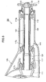
- Fig. 1 is a schematic cross sectional drawing showing a differential unit of the embodiment
- Fig. 2 is a schematic cross sectional drawing of essential elements thereof shown in Fig. 1.
- the differential unit 1 is enclosed in a case 5 with a differential cover (not shown) attached to an opening section of a differential carrier 3.
- a drive pinion shaft 9 is inserted into the inside of the case 5.
- a drive pinion (bevel pinion) 11 integrally formed on one end of the drive pinion shaft 9 and a driven gear (not shown) then engage with each other.
- a differential mechanism case (not shown) is attached to the driven gear with bolts (not shown), and the driven gear is rotatably supported by the differential mechanism case and the differential carrier 3.
- the drive pinion shaft 9 is rotatably supported on the differential carrier 3 by a single pilot bearing 13 and a pair of tapered roller bearings 15 and 17.
- a companion flange 19 for linking drive shafts (not shown) such as propeller shafts is spline fitted to the other end of the drive pinion shaft 9, and is fixed by press fitting to an inner race 13a of the pilot bearing 13 by the fastening force of a nut 21.
- the companion flange 19 is provided on an input axis end of the differential unit 1.
- the inside of the differential carrier 3 is airtightly sealed by an oil seal 23 provided between the differential carrier 3 and the companion flange 19.
- Cylindrical spacers 25 and 27 are respectively interposed not only between the inner race 13a of the pilot bearing and an inner race 15a of the front side tapered roller bearing 15 but also between the inner race 15a of the front side tapered roller bearing 15 and an inner race 17a of the rear side tapered roller bearing 17 on the drive pinion shaft 9.
- the spacers 25 and 27 restrict attachment positions of the pilot bearing 13 and the tapered roller bearings 15 and 17.
- a protruding section 31 protrudes towards the drive pinion shaft 9 at an inner side section facing the drive pinion shaft 9. And the protruding section 31 is integrally formed on the front side spacer 25 interposed between the inner races and 15a.
- the protruding section 31 is formed in a curved shape so as to be generally convex along the overall central axial direction of the spacer 25, and the cross sectional shape is arched.
- the protruding section 31 protrudes towards the drive pinion shaft 9 along the entire inner peripheral direction of the spacer 25 (outer peripheral direction of the drive pinion shaft 9), the inner surface of the protruding section 31 comes into contact with or close to the outer surface of the drive pinion shaft 9. In this way, as the inner surface comes into contact with or close to the outer surface of the drive pinion shaft 9, the rotational centers of the drive pinion shaft 9 and the spacer 25 become substantially aligned, there is little positional offset between them.
- the protruding section 31 is provided integrally with the spacer 25, there is no need to provide new components as the positional regulating means, and it becomes possible to reduce the numbers of components and assembly steps. As a result, it is possible to simply minimize the positional offset between the rotational centers of the drive pinion shaft 9 and the spacer 25 at low cost.
- FIG. 3 is a schematic cross sectional drawing showing essential elements in the modified example.
- the example shown in Fig. 3 and the embodiment shown in Fig. 2 are different with respect to the shape of the protruding section 31.
- a protruding section 41 is integrally provided at a specified position in the central axial direction of the spacer 25.
- the protruding section 41 is at a substantially central position in the central axial direction of the spacer 25.
- the protruding section 41 is provided to protrude thereof so as to face the drive pinion shaft 9 along the entire inner direction of the spacer 25 (outer direction of the drive pinion shaft 9) in the same way as shown in Fig. 2.
- the protruding section 41 is positioned between the drive pinion shaft 9 and the spacer 25, and the inner surface thereof comes into contact with or close to the outer surface of the drive pinion shaft 9.
- the positional offset between the rotational centers of the drive pinion shaft 9 and the spacer 25 is also reduced by the protruding section 41, and therefore it can reduce an imbalance arising with respect to the drive pinion shaft 9. Also, since the protruding section 41 is integrally provided with the spacer 25, similarly to the embodiment shown in Fig. 2, it is possible to simply prevent the positional offset between the rotational centers of the drive pinion shaft 9 and the spacer 25 at low cost.
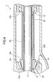
- FIG. 4 is a schematic cross sectional drawing showing the essential elements in the modified example shown in Fig. 4.
- the modified example shown in Fig. 4 and the embodiment shown in Fig. 2 are different in that the position regulating means is provided separately from the spacer.
- An O-ring 51 (position regulating means) is provided between the spacer 25 and the drive pinion shaft 9 as shown in Fig. 4.
- the O-ring 51 is arranged in the vicinity of an end section of the spacer 25 close to the tapered roller bearing 13.
- the O-ring 51 is made from metal or rubber.
- the O-ring 51 contacts with the outer surface of the drive pinion shaft 9 and the inner surface of the spacer 25. In this way, the rotational centers of the drive pinion shaft 9 and the spacer 25 become substantially aligned due to the fact that the O-ring 51 contacts with the outer surface of the drive pinion shaft 9 and the inner surface of the spacer 25, and therefore there is little positional offset between the rotational centers of the drive pinion shaft 9 and the spacer 25.
- the O-ring 51 is provided separately from the spacer 25, there is no need for design modifications accompanying change in shapes of the spacer 25. And it is simply possible to realize a structure for preventing the positional offset between the rotational centers of the drive pinion shaft 9 and the spacer 25 at low cost.
- Fig. 5 is a schematic cross sectional drawing showing essential parts in the modified example of this embodiment.
- the modified example shown in Fig. 5 and the modified example shown in Fig. 4 are different with regards to the number of O-rings and the positions at which the O-rings are arranged.
- O-rings 51 are arranged at two places in the vicinity of an end of the spacer 25 close to the tapered roller bearing 13 and in the vicinity of the end of the spacer 25 close to the tapered roller bearing 15.
- the present invention is not limited to the above described embodiment.
- a structure is possible having the position regulating means (such as the protruding section 31 or the O-ring 51) between the rear side spacer 27 interposed between the inner races of the pair of the tapered roller bearings 15 and 17, and the drive pinion shaft 9.
- the protruding sections 31 and 41 are provided so as to protrude towards the drive pinion shaft 9 along the entire inner direction of the spacer 25 (outer direction of the drive pinion shaft 9), but there is no limiting in that way. It is also possible to have the structure with the protruding sections 31 or 41 provided at the specified places on the inner peripheral direction of the spacer 25 (outer peripheral direction of the drive pinion shat 9) at three places spaced 120° apart or at 4 places spaced 90° apart, as long as the positional offset between the rotational centers of the drive pinion shaft 9 and the spacer 25 is reduced.
- the unit provided with the protruding section 31 or 41 is not limited to being positioned substantially centrally in the axial center direction, and it is possible to be positioned at the end of the spacer 25 in a central axial direction. It is possible to provide the protruding sections respectively at both ends of the spacer in the central axial direction.
- the differential unit of the present invention since there is the position regulating means between the drive pinion shaft and the spacer, the positional offset between the rotational centers of the pinion shaft and the spacer is reduced, and the spacer is prevented from becoming unbalanced. Accordingly, it is possible to provide the differential unit capable of reducing imbalance arising with respect to the drive pinion shaft.
Landscapes
- Engineering & Computer Science (AREA)
- General Engineering & Computer Science (AREA)
- Mechanical Engineering (AREA)
- Retarders (AREA)
- Motor Power Transmission Devices (AREA)
- General Details Of Gearings (AREA)
- Shafts, Cranks, Connecting Bars, And Related Bearings (AREA)
Applications Claiming Priority (2)
| Application Number | Priority Date | Filing Date | Title |
|---|---|---|---|
| JP2001063174A JP2002264675A (ja) | 2001-03-07 | 2001-03-07 | ディファレンシャル装置 |
| JP2001063174 | 2001-03-07 |
Publications (3)
| Publication Number | Publication Date |
|---|---|
| EP1239191A2 true EP1239191A2 (de) | 2002-09-11 |
| EP1239191A3 EP1239191A3 (de) | 2004-01-07 |
| EP1239191B1 EP1239191B1 (de) | 2006-08-09 |
Family
ID=18922208
Family Applications (1)
| Application Number | Title | Priority Date | Filing Date |
|---|---|---|---|
| EP02251525A Expired - Lifetime EP1239191B1 (de) | 2001-03-07 | 2002-03-05 | Differentialeinheit |
Country Status (4)
| Country | Link |
|---|---|
| US (1) | US7036391B2 (de) |
| EP (1) | EP1239191B1 (de) |
| JP (1) | JP2002264675A (de) |
| DE (1) | DE60213695T2 (de) |
Cited By (3)
| Publication number | Priority date | Publication date | Assignee | Title |
|---|---|---|---|---|
| GB2421987A (en) * | 2005-01-10 | 2006-07-12 | Hansen Transmissions Int | Bearing assembly |
| DE102006061258A1 (de) * | 2006-12-22 | 2008-06-26 | Zf Friedrichshafen Ag | Lageranordnung für eine Nebenabtriebswelle |
| ITTO20111181A1 (it) * | 2011-12-21 | 2013-06-22 | Gate Srl | Procedimento di montaggio di un albero in un elemento portante |
Families Citing this family (10)
| Publication number | Priority date | Publication date | Assignee | Title |
|---|---|---|---|---|
| EP1609997B1 (de) * | 2004-06-18 | 2007-08-08 | Electrolux Home Products Corporation N.V. | Lagerträger für ein Lüftergehäuse und Verfahren zu dessen Herstellung |
| KR100850974B1 (ko) | 2006-08-31 | 2008-08-12 | 현대자동차주식회사 | 마모방지형 내경을 갖는 디퍼런셜 피니언 기어 |
| DE102007059095A1 (de) | 2007-12-07 | 2009-06-10 | Schaeffler Kg | Distanzring |
| US20080296078A1 (en) * | 2007-05-30 | 2008-12-04 | American Axle & Manufacturing, Inc. | Torque transfer device with torque tube coupling mechanism |
| DE102013209579B3 (de) | 2013-05-23 | 2014-10-23 | Schaeffler Technologies Gmbh & Co. Kg | Getriebeeinheit |
| CN103388629A (zh) * | 2013-08-12 | 2013-11-13 | 沃德(天津)传动有限公司 | 一种轴承布置结构以及一种减速机 |
| DE102014112317A1 (de) * | 2014-08-27 | 2016-03-03 | Wittenstein Ag | Getriebe |
| US9664253B2 (en) | 2015-09-11 | 2017-05-30 | Gkn Driveline North America, Inc. | Crowned profile driveshaft journal |
| US10654569B2 (en) | 2018-07-30 | 2020-05-19 | Textron Innovations Inc. | Mast bearing system for a tiltrotor aircraft |
| CN109441957B (zh) * | 2018-11-26 | 2024-04-19 | 一汽解放汽车有限公司 | 一种上置导向轴承的主动锥齿轮总成 |
Family Cites Families (12)
| Publication number | Priority date | Publication date | Assignee | Title |
|---|---|---|---|---|
| USRE20149E (en) * | 1936-10-27 | Driving axle | ||
| US1556875A (en) * | 1923-11-12 | 1925-10-13 | Gen Motors Corp | Differential carrier |
| DE406049C (de) * | 1924-05-01 | 1924-11-15 | Fritz Kuehnel & Co G M B H | Befestigung von Kugellagern |
| US1956237A (en) * | 1928-12-14 | 1934-04-24 | Gen Motors Corp | Mounting for shafts |
| US2019464A (en) * | 1935-03-28 | 1935-10-29 | Timken Roller Bearing Co | Pinion shaft bearing |
| GB1400890A (en) * | 1973-06-23 | 1975-07-16 | Gkn Transmissions Ltd | Vehicle differential units |
| JP2519218B2 (ja) * | 1986-09-13 | 1996-07-31 | 富士重工業株式会社 | 回転装置並びに回転装置のプレロ−ド調整方法及びその調整装置 |
| JPH0740108Y2 (ja) * | 1987-03-12 | 1995-09-13 | トヨタ自動車株式会社 | 車両用動力伝達装置 |
| JPH0333539A (ja) * | 1989-06-29 | 1991-02-13 | Suzuki Motor Corp | デファレンシャル装置の組付方法 |
| EP0476458A1 (de) * | 1990-09-17 | 1992-03-25 | Steyr-Daimler-Puch Aktiengesellschaft | Kegelradgetriebe mit Tellerradabstützung |
| US5549397A (en) * | 1994-02-03 | 1996-08-27 | Temper Corporation | Adapter sleeve and an adjustable spacer with radial extension useable thereon |
| JPH08210472A (ja) * | 1995-02-02 | 1996-08-20 | Toyota Motor Corp | 終減速装置の潤滑機構 |
-
2001
- 2001-03-07 JP JP2001063174A patent/JP2002264675A/ja active Pending
-
2002
- 2002-03-05 DE DE60213695T patent/DE60213695T2/de not_active Expired - Fee Related
- 2002-03-05 EP EP02251525A patent/EP1239191B1/de not_active Expired - Lifetime
- 2002-03-06 US US10/090,754 patent/US7036391B2/en not_active Expired - Fee Related
Non-Patent Citations (1)
| Title |
|---|
| None |
Cited By (3)
| Publication number | Priority date | Publication date | Assignee | Title |
|---|---|---|---|---|
| GB2421987A (en) * | 2005-01-10 | 2006-07-12 | Hansen Transmissions Int | Bearing assembly |
| DE102006061258A1 (de) * | 2006-12-22 | 2008-06-26 | Zf Friedrichshafen Ag | Lageranordnung für eine Nebenabtriebswelle |
| ITTO20111181A1 (it) * | 2011-12-21 | 2013-06-22 | Gate Srl | Procedimento di montaggio di un albero in un elemento portante |
Also Published As
| Publication number | Publication date |
|---|---|
| EP1239191A3 (de) | 2004-01-07 |
| US7036391B2 (en) | 2006-05-02 |
| DE60213695T2 (de) | 2007-08-16 |
| US20020124672A1 (en) | 2002-09-12 |
| JP2002264675A (ja) | 2002-09-18 |
| EP1239191B1 (de) | 2006-08-09 |
| DE60213695D1 (de) | 2006-09-21 |
Similar Documents
| Publication | Publication Date | Title |
|---|---|---|
| EP1239191A2 (de) | Differentialeinheit | |
| US7216731B2 (en) | Motor-driven wheel small in size and improved in ride comfort, ease of assembly and reliability | |
| EP2615329B1 (de) | Geschwindigkeitsreduzierungsmechanismus und Motordrehmomentübertragungsvorrichtung damit | |
| US20060219037A1 (en) | Support structure and gear mechanism having the same | |
| EP2644425B1 (de) | Geschwindigkeitsreduzierungsmechanismus und Motordrehmomentübertragungsvorrichtung mit dem Geschwindigkeitsreduzierungsmechanismus | |
| JPH0328613B2 (de) | ||
| EP2246592B1 (de) | Reibungsrollenartiger getriebemechanismus | |
| US8152678B2 (en) | Hybrid differential gear device, differential case therefor and assembling method of differential case | |
| GB2089931A (en) | Epicyclic gearing drive for dredger drum | |
| US6200241B1 (en) | Differential and drive pinion assembly | |
| US12297893B2 (en) | Speed reducer | |
| JP2004155414A (ja) | タンデム駆動車軸セットのための車軸間差動アセンブリ | |
| JP3641519B2 (ja) | デファレンシャル装置 | |
| GB2092688A (en) | Gear noise suppressing type final gear train of transaxle | |
| JP4238577B2 (ja) | 電動パワーステアリング装置 | |
| US20050026734A1 (en) | Tandem axle pinion shaft subassembly | |
| JP3937556B2 (ja) | 複列円すいころ軸受装置 | |
| JP4501384B2 (ja) | 終減速機のドライブピニオン支持構造 | |
| JP2007271044A (ja) | 車輪用転がり軸受装置 | |
| US20240376974A1 (en) | Transmission for a Vehicle, Drive Train, and Method for Installing Such a Transmission | |
| JPH10100701A (ja) | 4輪駆動車の動力伝達装置 | |
| JPH0236735Y2 (de) | ||
| JPH05215120A (ja) | プロペラシャフト | |
| JPS62163829A (ja) | 4輪駆動装置 | |
| JP2004211875A (ja) | トルク伝達装置 |
Legal Events
| Date | Code | Title | Description |
|---|---|---|---|
| PUAI | Public reference made under article 153(3) epc to a published international application that has entered the european phase |
Free format text: ORIGINAL CODE: 0009012 |
|
| AK | Designated contracting states |
Kind code of ref document: A2 Designated state(s): AT BE CH CY DE DK ES FI FR GB GR IE IT LI LU MC NL PT SE TR |
|
| AX | Request for extension of the european patent |
Free format text: AL;LT;LV;MK;RO;SI |
|
| PUAL | Search report despatched |
Free format text: ORIGINAL CODE: 0009013 |
|
| AK | Designated contracting states |
Kind code of ref document: A3 Designated state(s): AT BE CH CY DE DK ES FI FR GB GR IE IT LI LU MC NL PT SE TR |
|
| AX | Request for extension of the european patent |
Extension state: AL LT LV MK RO SI |
|
| RIC1 | Information provided on ipc code assigned before grant |
Ipc: 7F 16C 35/06 B Ipc: 7F 16C 35/12 B Ipc: 7F 16H 57/02 A |
|
| 17P | Request for examination filed |
Effective date: 20040227 |
|
| 17Q | First examination report despatched |
Effective date: 20040420 |
|
| AKX | Designation fees paid |
Designated state(s): DE FR GB |
|
| GRAP | Despatch of communication of intention to grant a patent |
Free format text: ORIGINAL CODE: EPIDOSNIGR1 |
|
| GRAS | Grant fee paid |
Free format text: ORIGINAL CODE: EPIDOSNIGR3 |
|
| GRAA | (expected) grant |
Free format text: ORIGINAL CODE: 0009210 |
|
| AK | Designated contracting states |
Kind code of ref document: B1 Designated state(s): DE FR GB |
|
| REG | Reference to a national code |
Ref country code: GB Ref legal event code: FG4D |
|
| REF | Corresponds to: |
Ref document number: 60213695 Country of ref document: DE Date of ref document: 20060921 Kind code of ref document: P |
|
| EN | Fr: translation not filed | ||
| PLBE | No opposition filed within time limit |
Free format text: ORIGINAL CODE: 0009261 |
|
| STAA | Information on the status of an ep patent application or granted ep patent |
Free format text: STATUS: NO OPPOSITION FILED WITHIN TIME LIMIT |
|
| 26N | No opposition filed |
Effective date: 20070510 |
|
| GBPC | Gb: european patent ceased through non-payment of renewal fee |
Effective date: 20070305 |
|
| PG25 | Lapsed in a contracting state [announced via postgrant information from national office to epo] |
Ref country code: GB Free format text: LAPSE BECAUSE OF NON-PAYMENT OF DUE FEES Effective date: 20070305 Ref country code: FR Free format text: LAPSE BECAUSE OF FAILURE TO SUBMIT A TRANSLATION OF THE DESCRIPTION OR TO PAY THE FEE WITHIN THE PRESCRIBED TIME-LIMIT Effective date: 20070511 |
|
| PGFP | Annual fee paid to national office [announced via postgrant information from national office to epo] |
Ref country code: DE Payment date: 20080228 Year of fee payment: 7 |
|
| PG25 | Lapsed in a contracting state [announced via postgrant information from national office to epo] |
Ref country code: FR Free format text: LAPSE BECAUSE OF FAILURE TO SUBMIT A TRANSLATION OF THE DESCRIPTION OR TO PAY THE FEE WITHIN THE PRESCRIBED TIME-LIMIT Effective date: 20060809 |
|
| PG25 | Lapsed in a contracting state [announced via postgrant information from national office to epo] |
Ref country code: DE Free format text: LAPSE BECAUSE OF NON-PAYMENT OF DUE FEES Effective date: 20091001 |