EP1239299A2 - FMCW-Radarempfänger mit frequenzabhängiger Verstärkung - Google Patents
FMCW-Radarempfänger mit frequenzabhängiger Verstärkung Download PDFInfo
- Publication number
- EP1239299A2 EP1239299A2 EP02005051A EP02005051A EP1239299A2 EP 1239299 A2 EP1239299 A2 EP 1239299A2 EP 02005051 A EP02005051 A EP 02005051A EP 02005051 A EP02005051 A EP 02005051A EP 1239299 A2 EP1239299 A2 EP 1239299A2
- Authority
- EP
- European Patent Office
- Prior art keywords
- frequency
- signal
- circuit
- amplifier circuit
- gain
- Prior art date
- Legal status (The legal status is an assumption and is not a legal conclusion. Google has not performed a legal analysis and makes no representation as to the accuracy of the status listed.)
- Granted
Links
Images


Classifications
-
- G—PHYSICS
- G01—MEASURING; TESTING
- G01S—RADIO DIRECTION-FINDING; RADIO NAVIGATION; DETERMINING DISTANCE OR VELOCITY BY USE OF RADIO WAVES; LOCATING OR PRESENCE-DETECTING BY USE OF THE REFLECTION OR RERADIATION OF RADIO WAVES; ANALOGOUS ARRANGEMENTS USING OTHER WAVES
- G01S13/00—Systems using the reflection or reradiation of radio waves, e.g. radar systems; Analogous systems using reflection or reradiation of waves whose nature or wavelength is irrelevant or unspecified
- G01S13/02—Systems using reflection of radio waves, e.g. primary radar systems; Analogous systems
- G01S13/50—Systems of measurement based on relative movement of target
- G01S13/58—Velocity or trajectory determination systems; Sense-of-movement determination systems
- G01S13/583—Velocity or trajectory determination systems; Sense-of-movement determination systems using transmission of continuous unmodulated waves, amplitude-, frequency-, or phase-modulated waves and based upon the Doppler effect resulting from movement of targets
- G01S13/584—Velocity or trajectory determination systems; Sense-of-movement determination systems using transmission of continuous unmodulated waves, amplitude-, frequency-, or phase-modulated waves and based upon the Doppler effect resulting from movement of targets adapted for simultaneous range and velocity measurements
-
- G—PHYSICS
- G01—MEASURING; TESTING
- G01S—RADIO DIRECTION-FINDING; RADIO NAVIGATION; DETERMINING DISTANCE OR VELOCITY BY USE OF RADIO WAVES; LOCATING OR PRESENCE-DETECTING BY USE OF THE REFLECTION OR RERADIATION OF RADIO WAVES; ANALOGOUS ARRANGEMENTS USING OTHER WAVES
- G01S13/00—Systems using the reflection or reradiation of radio waves, e.g. radar systems; Analogous systems using reflection or reradiation of waves whose nature or wavelength is irrelevant or unspecified
- G01S13/02—Systems using reflection of radio waves, e.g. primary radar systems; Analogous systems
- G01S13/06—Systems determining position data of a target
- G01S13/08—Systems for measuring distance only
- G01S13/32—Systems for measuring distance only using transmission of continuous waves, whether amplitude-, frequency-, or phase-modulated, or unmodulated
- G01S13/34—Systems for measuring distance only using transmission of continuous waves, whether amplitude-, frequency-, or phase-modulated, or unmodulated using transmission of continuous, frequency-modulated waves while heterodyning the received signal, or a signal derived therefrom, with a locally-generated signal related to the contemporaneously transmitted signal
- G01S13/345—Systems for measuring distance only using transmission of continuous waves, whether amplitude-, frequency-, or phase-modulated, or unmodulated using transmission of continuous, frequency-modulated waves while heterodyning the received signal, or a signal derived therefrom, with a locally-generated signal related to the contemporaneously transmitted signal using triangular modulation
-
- G—PHYSICS
- G01—MEASURING; TESTING
- G01S—RADIO DIRECTION-FINDING; RADIO NAVIGATION; DETERMINING DISTANCE OR VELOCITY BY USE OF RADIO WAVES; LOCATING OR PRESENCE-DETECTING BY USE OF THE REFLECTION OR RERADIATION OF RADIO WAVES; ANALOGOUS ARRANGEMENTS USING OTHER WAVES
- G01S13/00—Systems using the reflection or reradiation of radio waves, e.g. radar systems; Analogous systems using reflection or reradiation of waves whose nature or wavelength is irrelevant or unspecified
- G01S13/88—Radar or analogous systems specially adapted for specific applications
- G01S13/93—Radar or analogous systems specially adapted for specific applications for anti-collision purposes
- G01S13/931—Radar or analogous systems specially adapted for specific applications for anti-collision purposes of land vehicles
-
- G—PHYSICS
- G01—MEASURING; TESTING
- G01S—RADIO DIRECTION-FINDING; RADIO NAVIGATION; DETERMINING DISTANCE OR VELOCITY BY USE OF RADIO WAVES; LOCATING OR PRESENCE-DETECTING BY USE OF THE REFLECTION OR RERADIATION OF RADIO WAVES; ANALOGOUS ARRANGEMENTS USING OTHER WAVES
- G01S7/00—Details of systems according to groups G01S13/00, G01S15/00, G01S17/00
- G01S7/02—Details of systems according to groups G01S13/00, G01S15/00, G01S17/00 of systems according to group G01S13/00
- G01S7/35—Details of non-pulse systems
- G01S7/352—Receivers
- G01S7/354—Extracting wanted echo-signals
-
- G—PHYSICS
- G01—MEASURING; TESTING
- G01S—RADIO DIRECTION-FINDING; RADIO NAVIGATION; DETERMINING DISTANCE OR VELOCITY BY USE OF RADIO WAVES; LOCATING OR PRESENCE-DETECTING BY USE OF THE REFLECTION OR RERADIATION OF RADIO WAVES; ANALOGOUS ARRANGEMENTS USING OTHER WAVES
- G01S7/00—Details of systems according to groups G01S13/00, G01S15/00, G01S17/00
- G01S7/02—Details of systems according to groups G01S13/00, G01S15/00, G01S17/00 of systems according to group G01S13/00
- G01S7/35—Details of non-pulse systems
- G01S7/352—Receivers
- G01S7/356—Receivers involving particularities of FFT processing
Definitions
- the present invention relates to a radar for detecting a vehicle, etc. using, for example, electromagnetic waves in the millimeter-wave band.
- the strength S of a reception signal received by a radar varies in accordance with distance.
- the strength S of a signal received by a radar is inversely proportional to R 4 ; therefore, when the radar is used over a large range from a short distance to a long distance, the strength S varies in a wide range in accordance with the distance of a target from an antenna.
- a beat signal obtained by mixing a reception signal and a transmission signal provides an intermediate-frequency signal (IF signal), and the strength of the IF signal is proportional to that of the reception signal.
- IF signal intermediate-frequency signal
- the gain of an amplifier circuit for amplifying the IF signal must be increased in order to compensate for the decrease in the strength of the reception signal.
- the gain of the amplifier circuit is too large, when a signal received from a short distance is amplified, the amplified signal exceeds the input range of an analog to distal (AD) converter, causing an overflow.
- AD analog to distal
- Japanese Unexamined Patent Application Publication No. 10-142322 and (5) Japanese Unexamined Patent Application Publication No. 7-77575 which each disclose a radar which generates a frequency-modulated transmission signal whose frequency varies with time, and which detects a distance to a target based on the beat frequency, wherein the gain of an amplifier circuit is varied in accordance with the beat frequency, considering that the strength of a signal received from a long distance is weak.
- the level of a noise signal generated within an amplifier increases in proportion to the passband width of the amplifier.
- An amplifier circuit for amplifying an IF signal in a radar requires a high SN ratio in order to amplify a weak signal.
- the gain of an amplifier increases as the frequency of the input signal increases, as in (4) and (5) described above, because the level of a noise signal in an output signal of the amplifier is proportional to the square root of the passband width, the noise signal increases and the SN ratio is thus degraded.
- the amplified IF signal is converted into digital data in an AD converter. If a frequency component at or above one half of the sampling frequency is present in an input signal to the AD converter, a problem occurs. That is, the frequency components at or above one half of the sampling frequency are folded over and superposed on the frequency components lower than the center frequency of the sampling frequency, causing a detection of a false image.
- the gain is decreased, inhibiting detection of small targets.
- the radars disclosed in (4) and (5) do not specify how to handle DC components and low-frequency components in the vicinity of DC in the IF signal.
- the DC component and low-frequency components in the vicinity of DC in the IF signal there have been problems to be solved as follows.
- a weak transmission signal (a leakage signal from a circulator) is provided, and to an RF signal input terminal of the mixer, a weak transmission signal Tm reflected or transmitted within the radar apparatus, as well as a reception signal S from a target, are provided.
- Tm a reception signal
- a high-frequency signal generated by a voltage-controlled oscillator VCO for generating a transmission signal causes noise signals in the vicinity of the carrier frequency, due to thermal noise, flicker noise in semiconductors, etc. These types of noise signals are referred to as a sideband noise signal and a phase noise signal.
- a frequency-modulated signal including the sideband noise signal or the phase noise signal is input to the local signal input terminal or the RF signal input terminal of the mixer, a noise signal is generated in the vicinity of DC.
- the DC and the noise signal in the vicinity of DC, superposed on the IF signal may reduce the sensitivity of the radar, degrade SN ratio, and cause an erroneous detection.
- the present invention in one aspect thereof, provides a radar for detecting the distance to a target based on the frequency difference between a transmission signal and a reception signal.
- the radar includes a transmission circuit for generating a frequency-modulated transmission signal whose frequency varies in time; a mixer circuit for generating an IF signal representing the frequency difference between a reception signal and the transmission signal; an amplifier circuit for amplifying the IF signal, the gain thereof having its peak at or below one half of a sampling frequency of an AD converter coupled to the output of the amplifier circuit, preferably at the frequency of an IF signal corresponding to a maximum detection distance; and the AD converter sampling the IF signal at a predetermined sampling frequency and converting from analog to digital.
- the maximum detection distance means the longest detection distance set in or expected for the radar.
- the frequency range of a signal which is input to the amplifier circuit is restricted, so that the SN ratio is improved.
- the present invention in another aspect thereof, provides a radar for detecting the distance to a target based on the frequency difference between a transmission signal and a reception signal.
- the radar includes a transmission circuit for generating a frequency-modulated transmission signal whose frequency varies in time; a mixer circuit for generating an IF signal representing the frequency difference between a reception signal and the transmission signal; an amplifier circuit for amplifying the IF signal; a DC blocking circuit provided at the input of the amplifier circuit; and an offset circuit for adding a predetermined DC offset, provided at the output of the amplifier circuit.
- the present invention in yet another aspect thereof, provides a radar for detecting the distance to a target based on the frequency difference between a transmission signal and a reception signal.
- the radar includes a transmission circuit for generating a frequency-modulated transmission signal whose frequency varies in time; a mixer circuit for generating an IF signal representing the frequency difference between a reception signal and the transmission signal; an amplifier circuit for amplifying the IF signal, the gain thereof having its peak at or below one half of a sampling frequency of an AD converter coupled to an output of the amplifier cicuit; the AD converter sampling the IF signal at a predetermined sampling frequency and converting from analog to digital; a first DC blocking circuit provided at the input of the amplifier circuit; a second DC blocking circuit provided at the output of the amplifier circuit; and an offset circuit, provided at the output of the amplifier circuit, for adding a predetermined DC offset to a signal from which the DC component has been removed by the second DC cutting circuit.
- the gain of the amplifier circuit preferably increases as the frequency rises in a range of at or below one half of the sampling frequency, preferably in a frequency range of the IF signal corresponding to distances not longer than a maximum detection distance.
- complex circuitry such as an AGC circuit is not required, serving to reduce the overall size and cost. Furthermore, unlike AGC circuits, an instantaneous change in the strength of the reception signal can be properly dealt with.
- the ratio of change in the gain of the amplifier relative to change in the frequency is preferably made smaller.
- the gain at short distances are made relatively larger so as to improve sensitivity, whereby the problem of relative insufficiency in sensitivity at short distances due to a saturation of the mixer is prevented.
- a target at a short distance can be accurately detected.
- Fig. 1 is a block diagram showing the overall construction of the radar.
- a voltage-controlled oscillator VCO1 changes the oscillation frequency in accordance with a control voltage output from a DA converter 10.
- An isolator 2 transmits an oscillation signal from the VCO1 to a coupler 3, inhibiting a reflection signal from being input to the VCO1.
- the coupler 3 transmits a signal from the isolator 2 to a circulator 4, and feeds a predetermined ratio of a transmission signal to a mixer 6 as a local signal Lo.
- the circulator 4 transmits the transmission signal to an antenna 5, and feeds a reception signal from the antenna 5 to the mixer 6.
- the antenna 5 transmits the continuous-wave transmission signal frequency modulated by the VCO1, and receives a reflection signal from the same direction.
- the antenna 5 also periodically changes the direction of beams over a range of detection angle.
- the mixer 6 mixes the local signal Lo from the coupler 3 and the reception signal from the circulator 4 to output an intermediate-frequency signal IF.
- An IF amplifier circuit 7 amplifies the intermediate frequency signal by a predetermined gain in accordance with the distance.
- An AD converter 8 converts the voltage signal into digital data, which is fed to a CPU 9.
- the CPU 9 calculates the distance of a target from the radar and the velocity of the target relative to the radar by a process to be described later.
- the CPU 9 also sequentially outputs digital data of the modulated signal to the DA converter 10, so that the VCO1 modulates the oscillation frequency continuously like a triangular waveform.
- Fig. 2 shows an example of deviation between the frequencies of the transmission signal and the reception signal due to the distance and relative velocity of the target.
- the upbeat frequency f BU represents the difference between the frequencies of the transmission signal and the reception signal while the frequency of the transmission signal is rising
- the downbeat frequency f BD represents the difference between the frequencies of the transmission signal and the reception signal when the frequency of transmission signal is falling.
- the deviation (time difference) between the triangular waves of transmission signal and reception signal along the time axis corresponds to the returning time of the electromagnetic waves from the antenna to the target.
- the deviation between the transmission signal and the reception signal along the frequency axis represents the amount of Doppler shift associated with the velocity of the target relative to the antenna.
- the upbeat frequency fBU and the downbeat frequency fBD vary in accordance with the time difference and the amount of Doppler shift.
- the distance of the target from the radar and the velocity of the target relative to the radar can be calculated by detecting the upbeat frequency fBU and the downbeat frequency fBD.
- f T denotes the transmission frequency
- f R denotes the reception frequency
- ⁇ denotes the width of frequency modulation
- fm denotes the repetition frequency
- R denotes the distance
- C denotes the speed of light.
- the Doppler shift frequency fd (2f T /C)V
- Fig. 3 is a flowchart showing a procedure to be executed by the CPU 9 shown in Fig. 1 to determine the distance and the relative velocity.
- FFT Fast Fourier Transform
- data sampled at a timing when a downbeat is generated is processed by FFT to determine frequency components in a downbeat period.
- a frequency corresponding to the peak of the frequency components is detected as a downbeat frequency.
- the distance of the target from the radar is calculated based on the sum of the upbeat frequency and the downbeat frequency. Also, the velocity of the target relative to the radar is calculated based on the difference between the upbeat frequency and the downbeat frequency.
- Fig. 4 shows the gain-frequency characteristics of the IF amplifier circuit 7 shown in Fig. 1. At frequencies lower than a frequency f IFmax of an IF signal which is generated when a reflection wave from a distance corresponding to one half of the sampling frequency, or preferably, a distance therewithin determined as a maximum detection distance, is received, the gain of the IF amplifier circuit 7 increases as the frequency becomes higher; whereas the gain decreases at frequencies above f IFmax .
- Fig. 5 shows an example of an IF amplifier circuit which exhibits the frequency characteristics described above.
- OP indicates a differential amplifier circuit (hereinafter referred to as an OP amp.) implemented by a low-noise signal amplifier.
- an OP amp. a differential amplifier circuit implemented by a low-noise signal amplifier.
- a series circuit of a capacitor C1 and a resistor R1 is connected between the input terminal IN of the IF amplifier circuit and the inverting input of the OP amp. OP.
- a parallel circuit of a capacitor C2 and a resistor R2 is connected.
- the non-inverting input of the OP amp. OP is grounded.
- Fig. 6 shows an example of variation in input signal Vin to the IF amplifier circuit 7 shown in Fig. 1 in relation to the distance R of a target from an antenna.
- the level of reception signal varies in accordance with the size of the target, such as a large-sized car, a standard-sized car, and a motorbike.
- the input signal Vin also varies accordingly at a gradient of 1/R 4 .
- a reflection signal from a nearby target is received, in the case of a large-sized car, at a distance nearer than a distance Ra, as the level of reception signal increases, a saturation is caused due to the characteristics of the mixer 6, causing the gradient of Vin relative to the distance R to be less steep than 1/R 4 .
- the IF amplifier circuit is implemented so as to have frequency characteristics in which the insufficiency in the gain at a distance shorter than the distance which causes a saturation of the mixer is compensated.
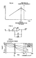
- Fig. 7 shows an example of the frequency characteristics of the IF amplifier circuit.
- the frequency fa is the frequency of an IF signal corresponding to the threshold distance Ra shown in Fig. 6 at which the saturation of the mixer begins.
- the IF amplifier circuit exhibits the same frequency characteristics as shown in Fig. 4 at frequencies higher than the frequency fa, and the ratio of change in the gain relative to change in the frequency is made smaller at frequencies lower than fa.
- an output voltage of the IF amplifier circuit 7 must be within the maximum input voltage V ADmax of an AD converter to which the output voltage is input. If the output voltage over the maximum voltage V ADmax is exceeded, the AD converter overflows, and an image signal is generated as a result of FFT. The image signal causes a target to been seen as if it were at a distance corresponding to the image frequency, causing an erroneous operation of the radar.
- the maximum allowable gain Amax of the IF amplifier circuit 7 is determined so that the condition of Amax ⁇ V ADmax /Vin is satisfied for each frequency, wherein Vin indicates a value in a case where a target having a maximum assumed scattering cross section is present.
- Fig. 8 shows an example implementation of an IF amplifier circuit which achieves the frequency characteristics described above.
- a circuit portion A1 comprises capacitors C11 and C12, resistors R11 and R12, and an OP amp. OP1, achieving low-frequency attenuation in accordance with the RC constant.
- the cutoff frequency is set preferably at the frequency f IFmax shown in Fig. 7.
- a circuit portion indicated by A2 comprises resistors R21 and R22, capacitors C21 and C22, and an OP amp. OP2, achieving high-frequency attenuation in accordance with the RC constant.
- the cutoff frequency is also set preferably at the frequency f IFmax shown in Fig. 7.
- a circuit portion indicated by A3 comprises resistors R31, R32, and R33, and an OP amp. OP3, forming an adder-amplifier circuit.
- Fig. 9 shows an example of the gain-frequency characteristics of an IF amplifier circuit.
- characteristics at zero frequency i.e., DC
- DC component or components in the vicinity thereof if included in an IF signal, may degrade sensitivity, deteriorate SN ratio, and cause an erroneous detection.
- the characteristics are such that the gain is zero at DC and the gain is decreased at frequencies lower than the frequency f IFmin of an IF signal corresponding to a minimum (shortest) detection distance.
- Fig. 10 shows an example implementation of an IF amplifier circuit which exhibits the gain-frequency characteristics shown in Fig. 9.
- A4 is a circuit comprising capacitors C41 and C42 and a resistor R41, which attenuates lower frequencies.
- the constructions of the portions indicated by A1, A2, and A3 are the same as those indicated by the same characters in Fig. 8.
- the characteristics shown in Fig. 9 in a range of zero frequency to the vicinity of the frequency f IFmin are achieved by the characteristics of the circuit portion indicated by A4 in Fig. 10.
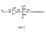
- Fig. 11 shows an example implementation of an IF amplifier circuit.
- AMP is an amplifier circuit which exhibits the gain-frequency characteristics shown in Fig. 7.
- a capacitor C51 is provided at the input of the amplifier circuit AMP.
- the capacitor C5 inhibits or blocks DC component and components in the vicinity thereof from entering the amplifier circuit AMP. By removing DC component and low-frequency components in the vicinity thereof from an input signal to the amplifier circuit AMP as described above, frequency characteristics similar to those shown in Fig. 9 are achieved.
- an offset circuit comprising a capacitor C52 and resistors R51 and R52 is provided.
- the resistors R51 and R52 provide a DC offset to an output signal from the amplifier circuit AMP.
- the capacitor C52 prevents the DC offset voltage from being applied to the output of the amplifier circuit AMP.
- the amplitude of an IF signal to the AD converter alternates with +1 V as the center.
Landscapes
- Engineering & Computer Science (AREA)
- Radar, Positioning & Navigation (AREA)
- Remote Sensing (AREA)
- Physics & Mathematics (AREA)
- Computer Networks & Wireless Communication (AREA)
- General Physics & Mathematics (AREA)
- Signal Processing (AREA)
- Electromagnetism (AREA)
- Radar Systems Or Details Thereof (AREA)
Applications Claiming Priority (2)
| Application Number | Priority Date | Filing Date | Title |
|---|---|---|---|
| JP2001061883 | 2001-03-06 | ||
| JP2001061883A JP2002257928A (ja) | 2001-03-06 | 2001-03-06 | レーダ |
Publications (3)
| Publication Number | Publication Date |
|---|---|
| EP1239299A2 true EP1239299A2 (de) | 2002-09-11 |
| EP1239299A3 EP1239299A3 (de) | 2003-03-05 |
| EP1239299B1 EP1239299B1 (de) | 2005-04-13 |
Family
ID=18921100
Family Applications (1)
| Application Number | Title | Priority Date | Filing Date |
|---|---|---|---|
| EP02005051A Expired - Lifetime EP1239299B1 (de) | 2001-03-06 | 2002-03-06 | FMCW-Radarempfänger mit frequenzabhängiger Verstärkung |
Country Status (4)
| Country | Link |
|---|---|
| US (1) | US6593874B2 (de) |
| EP (1) | EP1239299B1 (de) |
| JP (1) | JP2002257928A (de) |
| DE (1) | DE60203662T2 (de) |
Cited By (7)
| Publication number | Priority date | Publication date | Assignee | Title |
|---|---|---|---|---|
| WO2008071475A1 (de) * | 2006-12-11 | 2008-06-19 | Robert Bosch Gmbh | Verfahren zur erkennung einer vertikalen fehlausrichtung eines radarsensors |
| WO2009036816A1 (de) * | 2007-09-22 | 2009-03-26 | Abb Ag | System und verfahren zur erfassung und/oder erkennung von objekten bei robotergestützten produktions- und fertigungsprozessen |
| WO2009039896A1 (de) * | 2007-09-19 | 2009-04-02 | Abb Ag | System und verfahren zur geschwindigkeits- und/oder entfernungsmessung bei robotergestützten produktions- und fertigungsprozessen |
| CN101971050A (zh) * | 2009-05-20 | 2011-02-09 | 株式会社东芝 | 雷达装置 |
| EP2293099A1 (de) * | 2009-09-07 | 2011-03-09 | Alps Electric Co., Ltd. | Drahtlose Sensorvorrichtung |
| DE102013108489A1 (de) * | 2013-08-06 | 2015-02-12 | Finetek Co., Ltd. | Frequenzmodulierter Dauerstrich-Radarfüllstandsanzeiger und Signal-Verfolgungs- und Phasenrastungs-Verfahren hierfür |
| EP3786666A4 (de) * | 2018-04-27 | 2022-01-26 | Mitsumi Electric Co., Ltd. | Kurzstreckensensor |
Families Citing this family (15)
| Publication number | Priority date | Publication date | Assignee | Title |
|---|---|---|---|---|
| JP2003222672A (ja) * | 2002-01-30 | 2003-08-08 | Toyota Central Res & Dev Lab Inc | レーダ装置 |
| JP3925419B2 (ja) * | 2003-02-03 | 2007-06-06 | 株式会社デンソー | レーダ装置 |
| JP2007051888A (ja) * | 2005-08-16 | 2007-03-01 | Mitsubishi Electric Corp | レーダ装置 |
| JP4697072B2 (ja) * | 2006-07-04 | 2011-06-08 | 株式会社デンソー | レーダ装置 |
| JP2008170193A (ja) * | 2007-01-09 | 2008-07-24 | Mitsubishi Electric Corp | レーダ装置 |
| US7944391B2 (en) * | 2008-01-31 | 2011-05-17 | United Technologies Corporation | Correction for near field radar imaging |
| JP5319145B2 (ja) * | 2008-03-25 | 2013-10-16 | 株式会社東芝 | レーダー装置、レーダー装置の制御方法 |
| KR101081452B1 (ko) * | 2008-04-14 | 2011-11-09 | 한국전자통신연구원 | 자동 이득 제어기, 그것을 포함한 송수신기, 및 그것의자동 이득 제어 방법 |
| EP2636283B1 (de) | 2010-11-02 | 2018-08-29 | Philips Lighting Holding B.V. | Beleuchtungssystem mit radardetektion |
| JP5382087B2 (ja) * | 2011-11-02 | 2014-01-08 | 株式会社デンソー | レーダ装置 |
| JP5972203B2 (ja) * | 2013-03-25 | 2016-08-17 | 三菱電機株式会社 | Fm−cwレーダ装置 |
| TWI464441B (zh) * | 2013-08-28 | 2014-12-11 | U & U Engineering Inc | 具有距離閘功能之微波偵測器 |
| RU2584496C1 (ru) * | 2014-12-15 | 2016-05-20 | Федеральное государственное унитарное предприятие федеральный научно-производственный центр "Производственное объединение "Старт" им. М.В. Проценко" (ФГУП ФНПЦ ПО "Старт" им. М.В. Проценко") | Радиоволновое устройство для тревожной сигнализации с непрерывным излучением частотно-модулированных колебаний |
| DE102016204005A1 (de) * | 2016-03-11 | 2017-09-14 | Robert Bosch Gmbh | Vorrichtung zum Betreiben eines Radarsensors |
| JP6717254B2 (ja) * | 2017-04-19 | 2020-07-01 | 株式会社デンソー | レーダ信号処理器及びレーダシステム |
Family Cites Families (15)
| Publication number | Priority date | Publication date | Assignee | Title |
|---|---|---|---|---|
| US4733239A (en) | 1984-02-27 | 1988-03-22 | Schmitt Jerry C | Radar altimeter |
| US4901083A (en) | 1988-06-20 | 1990-02-13 | Delco Electronics Corporation | Near obstacle detection system |
| US4933641A (en) * | 1988-12-22 | 1990-06-12 | Itt Corporation | Extended dynamic range logarithmic if amplifying apparatus and method |
| GB2237470A (en) | 1989-09-04 | 1991-05-01 | Marconi Gec Ltd | Intruder alarm system |
| FR2669115B1 (fr) | 1990-11-09 | 1993-04-23 | Thomson Csf | Systeme radar en ondes millimetriques pour le guidage d'un robot mobile au sol. |
| US5361072A (en) * | 1992-02-28 | 1994-11-01 | Codar Ocean Sensors, Ltd. | Gated FMCW DF radar and signal processing for range/doppler/angle determination |
| JP2742373B2 (ja) | 1993-09-07 | 1998-04-22 | 本田技研工業株式会社 | レーダ装置 |
| JP3226399B2 (ja) | 1993-12-01 | 2001-11-05 | 富士通株式会社 | Fm−cwレーダ |
| JPH08160122A (ja) | 1994-12-02 | 1996-06-21 | Mitsubishi Electric Corp | Fmcwレーダ |
| JP3146903B2 (ja) | 1995-02-01 | 2001-03-19 | トヨタ自動車株式会社 | 車載用レーダ装置 |
| JP3511329B2 (ja) | 1995-06-09 | 2004-03-29 | 本田技研工業株式会社 | 車載用レーダ装置 |
| US5914683A (en) * | 1996-09-12 | 1999-06-22 | O'conner; Joe S. | Ultra high resolution ranging unit |
| JP2935419B2 (ja) | 1996-11-15 | 1999-08-16 | 本田技研工業株式会社 | Fmレーダ装置 |
| US6400308B1 (en) * | 1998-02-20 | 2002-06-04 | Amerigon Inc. | High performance vehicle radar system |
| DE19918767A1 (de) * | 1999-04-24 | 2000-10-26 | Daimler Chrysler Ag | Einrichtung zur Erhöhung des Dynamikbereichs von frequenzmodulierten Dauerstrichradaren |
-
2001
- 2001-03-06 JP JP2001061883A patent/JP2002257928A/ja active Pending
-
2002
- 2002-02-25 US US10/083,333 patent/US6593874B2/en not_active Expired - Fee Related
- 2002-03-06 EP EP02005051A patent/EP1239299B1/de not_active Expired - Lifetime
- 2002-03-06 DE DE60203662T patent/DE60203662T2/de not_active Expired - Lifetime
Cited By (15)
| Publication number | Priority date | Publication date | Assignee | Title |
|---|---|---|---|---|
| WO2008071475A1 (de) * | 2006-12-11 | 2008-06-19 | Robert Bosch Gmbh | Verfahren zur erkennung einer vertikalen fehlausrichtung eines radarsensors |
| WO2009039896A1 (de) * | 2007-09-19 | 2009-04-02 | Abb Ag | System und verfahren zur geschwindigkeits- und/oder entfernungsmessung bei robotergestützten produktions- und fertigungsprozessen |
| AT512731B1 (de) * | 2007-09-19 | 2014-03-15 | Abb Ag | System und verfahren zur geschwindigkeits- und/oder entfernungsmessung bei robotergestützten produktions- und fertigungsprozessen |
| AT512731A5 (de) * | 2007-09-19 | 2013-10-15 | Abb Ag | System und verfahren zur geschwindigkeits- und/oder entfernungsmessung bei robotergestützten produktions- und fertigungsprozessen |
| AT512732A5 (de) * | 2007-09-22 | 2013-10-15 | Abb Ag | System und verfahren zur erfassung und/oder erkennung von objekten bei robotergestützten produktions- und fertigungsprozessen |
| WO2009036816A1 (de) * | 2007-09-22 | 2009-03-26 | Abb Ag | System und verfahren zur erfassung und/oder erkennung von objekten bei robotergestützten produktions- und fertigungsprozessen |
| AT512732B1 (de) * | 2007-09-22 | 2014-02-15 | Abb Ag | System und verfahren zur erfassung und/oder erkennung von objekten bei robotergestützten produktions- und fertigungsprozessen |
| CN101971050A (zh) * | 2009-05-20 | 2011-02-09 | 株式会社东芝 | 雷达装置 |
| US8358235B2 (en) | 2009-09-07 | 2013-01-22 | Alps Electric Co., Ltd. | Wireless sensor device |
| CN102012507B (zh) * | 2009-09-07 | 2013-12-18 | 阿尔卑斯电气株式会社 | 无线传感器装置 |
| CN102012507A (zh) * | 2009-09-07 | 2011-04-13 | 阿尔卑斯电气株式会社 | 无线传感器装置 |
| EP2293099A1 (de) * | 2009-09-07 | 2011-03-09 | Alps Electric Co., Ltd. | Drahtlose Sensorvorrichtung |
| DE102013108489A1 (de) * | 2013-08-06 | 2015-02-12 | Finetek Co., Ltd. | Frequenzmodulierter Dauerstrich-Radarfüllstandsanzeiger und Signal-Verfolgungs- und Phasenrastungs-Verfahren hierfür |
| DE102013108489B4 (de) * | 2013-08-06 | 2018-01-18 | Finetek Co., Ltd. | Frequenzmodulierter Dauerstrich-Radarfüllstandsanzeiger |
| EP3786666A4 (de) * | 2018-04-27 | 2022-01-26 | Mitsumi Electric Co., Ltd. | Kurzstreckensensor |
Also Published As
| Publication number | Publication date |
|---|---|
| JP2002257928A (ja) | 2002-09-11 |
| EP1239299A3 (de) | 2003-03-05 |
| US20020154051A1 (en) | 2002-10-24 |
| DE60203662T2 (de) | 2006-03-02 |
| DE60203662D1 (de) | 2005-05-19 |
| US6593874B2 (en) | 2003-07-15 |
| EP1239299B1 (de) | 2005-04-13 |
Similar Documents
| Publication | Publication Date | Title |
|---|---|---|
| EP1239299B1 (de) | FMCW-Radarempfänger mit frequenzabhängiger Verstärkung | |
| US7187321B2 (en) | Interference determination method and FMCW radar using the same | |
| US6597308B2 (en) | Radar apparatus | |
| JP3726441B2 (ja) | レーダ装置 | |
| RU2659331C2 (ru) | Гомодинный приемник и способ преодоления шума смещения постоянного тока в гомодинном приемнике | |
| US7791532B2 (en) | Radar | |
| US20180011181A1 (en) | Radar systems and methods thereof | |
| US11029388B2 (en) | Spectral estimation of noise in radar apparatus | |
| US20170315211A1 (en) | Loopback Techniques for Synchronization of Oscillator Signal in Radar | |
| JP3600499B2 (ja) | Fmパルスドップラーレーダー装置 | |
| US20190170857A1 (en) | Radar transceiver | |
| EP1321775A1 (de) | Fm-cw radarvorrichtung | |
| EP1262793A1 (de) | Verfahren und Vorrichtung zur Beseitigung des Gleichanteils im Frequenzspektrum vor der Durchführung einer Fouriertransformation in einem Radargerät | |
| JPH11287853A (ja) | レーダ装置 | |
| US6229474B1 (en) | Radar apparatus | |
| EP1462818A1 (de) | Verstärkungsreglung für FM-CW Radar mit einzelner Antenne | |
| JP2001318143A (ja) | Fm−cwレーダ | |
| US6839019B2 (en) | Pulse radar device | |
| JP3473577B2 (ja) | レーダー装置 | |
| JP3930376B2 (ja) | Fmcwレーダ装置 | |
| JP2803686B2 (ja) | Fm―cwレーダ装置用受信機およびfm―cwレーダ装置 | |
| JP2762143B2 (ja) | 間欠fm―cwレーダ装置 | |
| JP2004245647A (ja) | 近距離レーダ装置および近距離レーダ装置を搭載した車両 | |
| US20240288532A1 (en) | Radar apparatus and interference wave avoidance device | |
| JP3524231B2 (ja) | Fm−cwレーダ装置及びfm−cwレーダ法における雑音成分判定方法 |
Legal Events
| Date | Code | Title | Description |
|---|---|---|---|
| PUAI | Public reference made under article 153(3) epc to a published international application that has entered the european phase |
Free format text: ORIGINAL CODE: 0009012 |
|
| 17P | Request for examination filed |
Effective date: 20020306 |
|
| AK | Designated contracting states |
Kind code of ref document: A2 Designated state(s): AT BE CH CY DE DK ES FI FR GB GR IE IT LI LU MC NL PT SE TR |
|
| AX | Request for extension of the european patent |
Free format text: AL;LT;LV;MK;RO;SI |
|
| PUAL | Search report despatched |
Free format text: ORIGINAL CODE: 0009013 |
|
| AK | Designated contracting states |
Kind code of ref document: A3 Designated state(s): AT BE CH CY DE DK ES FI FR GB GR IE IT LI LU MC NL PT SE TR |
|
| AX | Request for extension of the european patent |
Extension state: AL LT LV MK RO SI |
|
| AKX | Designation fees paid |
Designated state(s): DE FR GB |
|
| 17Q | First examination report despatched |
Effective date: 20040128 |
|
| GRAP | Despatch of communication of intention to grant a patent |
Free format text: ORIGINAL CODE: EPIDOSNIGR1 |
|
| GRAS | Grant fee paid |
Free format text: ORIGINAL CODE: EPIDOSNIGR3 |
|
| GRAA | (expected) grant |
Free format text: ORIGINAL CODE: 0009210 |
|
| AK | Designated contracting states |
Kind code of ref document: B1 Designated state(s): DE FR GB |
|
| REG | Reference to a national code |
Ref country code: GB Ref legal event code: FG4D |
|
| REG | Reference to a national code |
Ref country code: IE Ref legal event code: FG4D |
|
| REF | Corresponds to: |
Ref document number: 60203662 Country of ref document: DE Date of ref document: 20050519 Kind code of ref document: P |
|
| PLBE | No opposition filed within time limit |
Free format text: ORIGINAL CODE: 0009261 |
|
| STAA | Information on the status of an ep patent application or granted ep patent |
Free format text: STATUS: NO OPPOSITION FILED WITHIN TIME LIMIT |
|
| ET | Fr: translation filed | ||
| 26N | No opposition filed |
Effective date: 20060116 |
|
| PGFP | Annual fee paid to national office [announced via postgrant information from national office to epo] |
Ref country code: DE Payment date: 20130227 Year of fee payment: 12 Ref country code: FR Payment date: 20130325 Year of fee payment: 12 Ref country code: GB Payment date: 20130306 Year of fee payment: 12 |
|
| REG | Reference to a national code |
Ref country code: DE Ref legal event code: R119 Ref document number: 60203662 Country of ref document: DE |
|
| GBPC | Gb: european patent ceased through non-payment of renewal fee |
Effective date: 20140306 |
|
| REG | Reference to a national code |
Ref country code: FR Ref legal event code: ST Effective date: 20141128 |
|
| REG | Reference to a national code |
Ref country code: DE Ref legal event code: R119 Ref document number: 60203662 Country of ref document: DE Effective date: 20141001 |
|
| PG25 | Lapsed in a contracting state [announced via postgrant information from national office to epo] |
Ref country code: DE Free format text: LAPSE BECAUSE OF NON-PAYMENT OF DUE FEES Effective date: 20141001 Ref country code: GB Free format text: LAPSE BECAUSE OF NON-PAYMENT OF DUE FEES Effective date: 20140306 Ref country code: FR Free format text: LAPSE BECAUSE OF NON-PAYMENT OF DUE FEES Effective date: 20140331 |