EP1239980B1 - Verfahren zur herstellung von stützpfeilern - Google Patents
Verfahren zur herstellung von stützpfeilern Download PDFInfo
- Publication number
- EP1239980B1 EP1239980B1 EP00971130A EP00971130A EP1239980B1 EP 1239980 B1 EP1239980 B1 EP 1239980B1 EP 00971130 A EP00971130 A EP 00971130A EP 00971130 A EP00971130 A EP 00971130A EP 1239980 B1 EP1239980 B1 EP 1239980B1
- Authority
- EP
- European Patent Office
- Prior art keywords
- indentations
- metal blank
- support pillars
- pillars
- extend
- Prior art date
- Legal status (The legal status is an assumption and is not a legal conclusion. Google has not performed a legal analysis and makes no representation as to the accuracy of the status listed.)
- Expired - Lifetime
Links
Images



Classifications
-
- E—FIXED CONSTRUCTIONS
- E06—DOORS, WINDOWS, SHUTTERS, OR ROLLER BLINDS IN GENERAL; LADDERS
- E06B—FIXED OR MOVABLE CLOSURES FOR OPENINGS IN BUILDINGS, VEHICLES, FENCES OR LIKE ENCLOSURES IN GENERAL, e.g. DOORS, WINDOWS, BLINDS, GATES
- E06B3/00—Window sashes, door leaves, or like elements for closing wall or like openings; Layout of fixed or moving closures, e.g. windows in wall or like openings; Features of rigidly-mounted outer frames relating to the mounting of wing frames
- E06B3/66—Units comprising two or more parallel glass or like panes permanently secured together
- E06B3/663—Elements for spacing panes
- E06B3/66304—Discrete spacing elements, e.g. for evacuated glazing units
-
- B—PERFORMING OPERATIONS; TRANSPORTING
- B21—MECHANICAL METAL-WORKING WITHOUT ESSENTIALLY REMOVING MATERIAL; PUNCHING METAL
- B21F—WORKING OR PROCESSING OF METAL WIRE
- B21F45/00—Wire-working in the manufacture of other particular articles
-
- B—PERFORMING OPERATIONS; TRANSPORTING
- B23—MACHINE TOOLS; METAL-WORKING NOT OTHERWISE PROVIDED FOR
- B23D—PLANING; SLOTTING; SHEARING; BROACHING; SAWING; FILING; SCRAPING; LIKE OPERATIONS FOR WORKING METAL BY REMOVING MATERIAL, NOT OTHERWISE PROVIDED FOR
- B23D31/00—Shearing machines or shearing devices covered by none or more than one of the groups B23D15/00 - B23D29/00; Combinations of shearing machines
- B23D31/002—Breaking machines, i.e. pre-cutting and subsequent breaking
Definitions
- This invention relates to a method of producing support pillars for use in maintaining two glass sheets of an evacuated glass panel in spaced-apart relationship.
- the invention has application and is hereinafter described in the context of vacuum glazing.
- the document WO-A-96/12862 discloses a method of producing support pillars for use in the fabrication of evacuated glass panels.
- Vacuum glazing typically comprises two confronting plane sheets of glass which are joined together and are hermetically sealed around their marginal edges.
- the glass sheets are separated by an evacuated space, and the separation is maintained against atmospheric pressure by an array of support pillars.
- the pillars typically are 0.1 to 0.2 mm high and have lateral dimensions in the order of 0.2 to 0.5 mm. Also, the pillars are distributed in the array with the spacing between neighbouring pillars being in the order of 20 to 30 mm.
- the shape and dimensions of the support pillars are critical.
- the two bearing surfaces of each pillar should be smooth and accurately parallel, whilst all pillars must have substantially the same height to within close tolerances, typically in the order of ⁇ 2 ⁇ m.
- each pillar is placed on the upper surface of one of the glass sheets and, during this placement operation, it is essential that each pillar should stand on one of its bearing surfaces. If the pillars are incorrectly orientated they will have an inappropriate height. For example, in the case of pillars in the form of rectangular prisms, incorrectly orientated pillars will have heights that are greater than that of the surrounding pillars, and this will cause excessive stress in and localised damage to the glass sheets when the space between the sheets is evacuated.
- the pillars may be made from solder glass, a low melting point glass with a coefficient of expansion close to that of the glass sheets.
- the solder glass is deposited as a powder, slurry or as pre-forms on one of the glass sheets.
- the solder glass melts during the high temperature operation that is employed to form the edge seal and fuses to the glass sheets. Thereafter, the solder glass solidifies, on cooling, to form the support pillars.
- Composite pillars have also been described. Each of these pillars consists of a non-melting core which is surrounded by solder glass.
- Metal pillars have also been used in vacuum glazing.
- Metal pillars typically are formed from sheet material using double sided photolithography and chemical or electrolytic etching. Such a process results in the formation of a pillar having an edge shape that causes it automatically to stand on one of its bearing surfaces when placed on the supporting glass sheet.
- Cylindrical metal pillars have also been produced by punching. With this manufacturing method, however, it is difficult to achieve a smooth face on the surface of the pillar that is impacted during the punching operation due to dimensional characteristics of the punching tool. Some post-punching treatment is therefore normally required for such pillars to remove a burr from the impacted face.
- punched pillars may rest on one of their sides, during positioning on the glazing, and may not stand on their bearing surfaces.
- punching is not suitable for producing such a pillar because the soft metal on the impacted face of the pillar results in an even larger burr than occurs on punched pillars without soft end caps.
- Ceramic materials have also been employed for use in fabricating pillars for use in vacuum glazing. Individual pillars are cut from a ceramic sheet using a diamond saw and this method would, in principle, be suitable for making composite pillars with a high strength ceramic core and soft end caps.
- a disadvantage of this method is that the pillars are cut in the form of rectangular prisms and individual pillars may therefore rest on their sides during the placement process.
- the pillars made by this method are costly because of the slow speed of the diamond sawing operation.
- the present invention seeks to provide a method of producing support pillars which avoids or diminishes the above mentioned problems of the prior art methods.
- the present invention provides a method of producing support pillars for use in the fabrication of evacuated glass panels and which comprises the steps of:
- the indentations may be formed with a tool that has two inclined cutting surfaces, so that a linearly extending V-shaped indentation will be created.
- the cutting surfaces of the tool may be inclined symmetrically or asymmetrically.
- the indenting tool preferably is provided with one vertical cutting surface and one inclined cutting surface, so that two tools may be aligned with respect to their vertical surfaces.
- the indentations may be formed to a depth which is just sufficient to enable the individual support pillars to be broken away from the metal blank.
- the indentations may be formed to a depth which results automatically in parting of the individual support pillars from the blank, due to a minuscule amount of material being left in the region of weakness between the respective pairs of indentations.
- the indentations are not formed to such a depth as would cause convergence of the (opposing) indentations of each pair. To effect convergence of the opposing indentations of each pair would require that opposing indenting tools should actually meet, with a possibility of them crashing and sustaining damage, and this clearly would not be a desirable outcome.
- the metal blank may have any one of a number of configurations.
- it may be in the form of a metal strip, a plate or a wire.
- the metal blank When the metal blank has a width larger than the desired width of the support pillars, the metal blank will be scored with orthogonal pairs of aligned linearly extending indentations.
- the method of the present invention will further comprise the step of rolling the metal blank into a strip having the desired thickness of the support pillars.
- the rolling step may be performed simultaneously with the formation of the indentations or be performed as a separate step prior to the formation of the indentations.
- the support pillars may comprise composite structures, in which case the method of the present invention will further comprise the step of forming a coating on at least one surface of the metal blank prior to formation of the indentations. Thereafter, the indentations preferably will be formed in a manner to ensure that they extend through the coating and into the substrate of the metal blank.
- the coating will preferably be formed from a relatively soft material, whilst the substrate will be formed from a material that has a high compressive strength.
- the method of the present invention most preferably comprises the steps of forming coatings on both of the opposite surfaces of the substrate.
- a metal blank 10 in the form of a metal sheet is employed as a starting material.
- the sheet has a thickness that is equal to the required thickness of the support pillars that are to be produced from the sheet.
- Pairs of aligned linearly extending indentations 13 and 14 are formed in opposite surfaces 15 and 16 of the metal blank 10.
- the indentations 13 and 14 of each pair extend parallel with one another and linearly across the width of the metal blank 10.
- Indenting tools (or blades) 19 and 20 are employed to form the indentations 13, 14 and 17, 18.
- Each of the tools has a vertical cutting surface 21 and an inclined cutting surface 22, and the tools are forced into the opposite surfaces of the metal blank, as shown in figure 1(b) , to create the linearly extending indentations as shown in Figure 1(c) .
- regions 23 of weakness are created that extend between the troughs 24 of the respective pairs of indentations 13 and 14 or 17 and 18. Also, in forcing the indentations into the opposing surfaces of the metal blank, a curved wall 25 is created at one side of each indentation and a chamfered wall 26 is created at the other side of each indentation. Thus, an asymmetrical V-shaped indentation is created.
- the metal blank 10 When forming the second series of indentations 17 and 18, the metal blank 10 may be rotated through 90° and be reinserted between the same indenting tools 19 and 20 as are used in forming the first series of indentations 13 and 14.
- the resultant (intermediate) product is as shown in Figure 1(d) , having a number of rectangular portions separated by the orthogonally extending indentations.
- one strip 27 of the rectangular portions is broken away from the metal blank 10 by parting it along the region of weakness 23 that extends between the troughs 24 of the respective pairs of indentations.
- individual support pillars 28 are broken away from the strip 27, as shown in Figure 1(f) , again by parting the support pillar along the region of weakness 23.
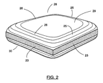
- each resultant support pillar has marginal edges 23 (corresponding to the respective zones of weakness) which have cross-sectional areas that are very small relative to the cross-sectional areas of the top and bottom (bearing) surfaces 29 and 30 of the pillar.
- This coupled with the curved and chamfered wall portions 25 and 26, ensures that the pillars will rest on one or the other of the bearing surfaces 29 or 30.
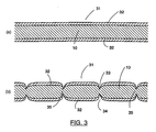
- a metal blank 31 comprises a metal sheet 10 that is clad on its opposite surfaces with a cladding material 32 that is soft in relation to the material from which the metal sheet 10 is formed.
- the metal sheet 10 is composed of a material having a compressive strength sufficient to withstand the compressive force exerted by spaced-apart glass sheets under the previously described conditions.
- the clad metal blank 31 of Figures 3(a) and (b) is formed with indentations 33 and 34 in the same manner as described with reference to Figures 1(a) to (f) , but care must be taken to ensure that the indentations 33 and 34 extend through the cladding material 32 and enter the substrate material 10. This is required in order to create a region of weakness 35, within the substrate metal 10, between the troughs of the respective pairs of indentations 33 and 34.
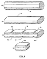
- the support pillars may be formed from wire as shown in Figures 4(a) to (d) of the drawings.
- wire 36 which has a high compressive strength in a radial direction is rolled to form a strip-form metal blank 37 having a minor axis thickness that is equal to the required thickness of the pillars.
- a single series of parallel indentations is formed in the metal blank 37, with respective pairs of linearly extending indentations 38 and 39 being formed in opposite surfaces 40 and 41 of the metal blank.
- the indentations 38 and 39 may be formed in the same manner as the indentation 13 and 14 in the arrangement shown in Figure 1(c) .
- individual pillars 42 may be parted from the metal blank in the manner as above described.
- Figures 5 and 6 show alternative methods of cladding the strip-form metal blank 37 of Figures 4(a) to (d) with a relatively soft cladding material, so as to produce a composite metal blank that is akin to that shown in Figure 3(a) .
- the cladding material 43 is applied as a sleeve that surrounds the substrate of the metal blank, whereas in Figure 6 the cladding material is bonded as laminates to opposed surfaces of the substrate that forms the metal blank.
- Figures 7(a) and (b) and Figures 8(a) and (b) illustrate further methods of forming the support pillars.
- a first pair of indenting blades 45 is employed to create linear indentations that define successive strips 46 that are parted from a metal blank 47, and a second pair of indenting blades 48 is employed to create the indentations that permit parting of individual pillars 49 from the strip 46.
- the blades are actuated in the directions indicated by arrows 50 and 51 and the blades are moved sufficiently close to one another as to leave only a minuscule amount of metal in the region of weakness 54 between the opposing indentations of each pair of indentations.
Landscapes
- Engineering & Computer Science (AREA)
- Mechanical Engineering (AREA)
- Civil Engineering (AREA)
- Structural Engineering (AREA)
- Joining Of Glass To Other Materials (AREA)
- Forging (AREA)
- Mechanical Treatment Of Semiconductor (AREA)
- Laminated Bodies (AREA)
- Crystals, And After-Treatments Of Crystals (AREA)
Claims (18)
- Verfahren zur Erzeugung von Sützpfeilern zur Verwendung bei der Herstellung evakuierter Glasscheiben, das die Schritte umfasst, dass:(a) in gegenüberliegenden Fächen (15, 16) eines Metallrohlings (10) Paare von ausgerichteten, sich linear erstreckenden Einkerbungen (13, 14) geformt und infolgedessen Schwachstellengebiete (23) erzeugt werden, die sich zwischen Mulden (24) der jeweiligen Paare von Einkerbungen erstrecken, und(b) einzelne der Sützpfeiler von dem Metallrohling an den jeweiligen Schwachstellengebieten abgetrennt werden.
- Verfahren nach Anspruch 1, wobei die Einkerbungen jedes Paares bis zu einer Tiefe geformt werden, die ausreichend ist, um zu ermöglichen, dass einzelne der Sützpfeiler von dem Rohling an den Schwachstellengebieten zwischen den Mulden der jeweiligen Paare von Einkerbungen weggebrochen werden können.
- Verfahren nach Anspruch 1, wobei die Einkerbungen jedes Paares bis zu einer Tiefe geformt werden, so dass die Mulden der jeweiligen Paare von Einkerbungen nahezu konvergieren und sich infolgedessen einzelne der Stützpfeiler selbsttätig von dem Metallrohling abtrennen.
- Verfahren nach einem der Ansprüche 1 bis 3, wobei jede Einkerbung ein Profil besitzt, das bei Betrachtung in der linearen Richtung der Einkerbung im Wesentlichen V-formig ist.
- Verfahren nach Anspruch 4, wobei jede Einkerbung eine asymmetrische V-Form besitzt.
- Verfahren nach einem der vorhergehenden Ansprüche, wobei jede Einkerbung durch ein Einkerbwerkzeug (19, 20) geformt wird, das eine vertikale erste Schneidfläche (21), eine zweite Schneidfläche (22), die in Bezug auf die erste Schneidfläche schräg gestellt ist, und einen spitzen eingeschlossenen Winkel zwischen der ersten und zweiten Schneidfläche besitzt.
- Verfahren nach einem der vorhergehenden Ansprüche, wobei der Metallrohling in der Form eines im Wesentlichen flachen Blechs vorgesehen wird.
- Verfahren nach Anspruch 7, wobei periodisch beabstandete Paare der Einkerbungen (13, 14) so geformt werden, dass sie sich in einer ersten Richtung erstrecken, und ferner periodisch beabstandete Paare von Einkerbungen (17, 18) so geformt werden, dass sie sich in einer zweiten Richtung erstrecken, die orthogonal zu der ersten Richtung ist.
- Verfahren nach einem der Ansprüche 1 bis 6, wobei der Metallrohling in der Form eines Streifens vorgesehen wird und wobei periodisch beabstandete Paare der Einkerbungen so geformt werden, dass sie sich in der linearen Richtungüber die Breite des Streifens erstrecken.
- Verfahren nach Anspruch 9, wobei der Streifen aus einem Draht mit kreisformigem Querschnitt gewalzt wird, um den Metallrohling zu formen.
- Verfahren nach Anspruch 10, wobei das Walzen des Drahtes gleichzeitig mit der Formung der Einkerbungen ausgeführt wird.
- Verfahren nach Anspruch 10, wobei das Walzen des Drahtes vor der Formung der Einkerbungen ausgeführt wird.
- Verfahren nach einem der vorhergehenden Ansprüche, wobei der Metallrohling durch Beschichten zumindest einer Fläche eines Metallsubstrats mit einer Plattierung (32) geformt wird.
- Verfahren nach Anspruch 13, wobei die Plattierung auf entgegengesetzten Flächen des Substrats vorgesehen wird.
- Verfahren nach einem der Ansprüche 13 oder 14, wobei die Plattierung aus einem Material besteht, das in Bezug auf das Material des Substrats weich ist.
- Verfahren nach einem der Ansprüche 13 bis 15, wobei die Einkerbungen so geformt werden, dass sie sich durch die Plattierung und in das Substrat erstrecken.
- Verfahren nach einem der vorhergehenden Ansprüche, wobei zumindest ein Teil der Einkerbungen durch ein Einkerbwerkzeug in der Form einer hin- und herverlaufenden Klinge (45) geformt wird.
- Verfahren nach einem der Ansprüche 1 bis 16, wobei zumindest ein Teil der Einkerbungen durch ein Einkerbwerkzeug in der Form einer rotierenden Scheibe (52) geformt wird.
Applications Claiming Priority (3)
| Application Number | Priority Date | Filing Date | Title |
|---|---|---|---|
| AUPQ3494A AUPQ349499A0 (en) | 1999-10-18 | 1999-10-18 | Method of producing support pillars |
| AUPQ349499 | 1999-10-18 | ||
| PCT/AU2000/001265 WO2001028707A1 (en) | 1999-10-18 | 2000-10-18 | Method of producing support pillars |
Publications (3)
| Publication Number | Publication Date |
|---|---|
| EP1239980A1 EP1239980A1 (de) | 2002-09-18 |
| EP1239980A4 EP1239980A4 (de) | 2006-07-05 |
| EP1239980B1 true EP1239980B1 (de) | 2008-04-23 |
Family
ID=3817648
Family Applications (1)
| Application Number | Title | Priority Date | Filing Date |
|---|---|---|---|
| EP00971130A Expired - Lifetime EP1239980B1 (de) | 1999-10-18 | 2000-10-18 | Verfahren zur herstellung von stützpfeilern |
Country Status (8)
| Country | Link |
|---|---|
| US (1) | US6966208B1 (de) |
| EP (1) | EP1239980B1 (de) |
| JP (1) | JP2003512278A (de) |
| AT (1) | ATE392962T1 (de) |
| AU (1) | AUPQ349499A0 (de) |
| CA (1) | CA2387577C (de) |
| DE (1) | DE60038696T2 (de) |
| WO (1) | WO2001028707A1 (de) |
Cited By (1)
| Publication number | Priority date | Publication date | Assignee | Title |
|---|---|---|---|---|
| CN108290199A (zh) * | 2016-02-01 | 2018-07-17 | 宝马股份公司 | 用于加工和/或制造构件的方法和设备以及这样的构件 |
Families Citing this family (18)
| Publication number | Priority date | Publication date | Assignee | Title |
|---|---|---|---|---|
| US6962834B2 (en) * | 2002-03-22 | 2005-11-08 | Stark David H | Wafer-level hermetic micro-device packages |
| US20060191215A1 (en) * | 2002-03-22 | 2006-08-31 | Stark David H | Insulated glazing units and methods |
| US7832177B2 (en) | 2002-03-22 | 2010-11-16 | Electronics Packaging Solutions, Inc. | Insulated glazing units |
| US7989040B2 (en) | 2007-09-14 | 2011-08-02 | Electronics Packaging Solutions, Inc. | Insulating glass unit having multi-height internal standoffs and visible decoration |
| US7851034B2 (en) * | 2007-12-03 | 2010-12-14 | Guardian Industries Corp. | Embedded vacuum insulating glass unit, and/or method of making the same |
| WO2010019484A2 (en) | 2008-08-09 | 2010-02-18 | Eversealed Windows, Inc. | Asymmetrical flexible edge seal for vacuum insulating glass |
| US8329267B2 (en) | 2009-01-15 | 2012-12-11 | Eversealed Windows, Inc. | Flexible edge seal for vacuum insulating glazing units |
| US8512830B2 (en) | 2009-01-15 | 2013-08-20 | Eversealed Windows, Inc. | Filament-strung stand-off elements for maintaining pane separation in vacuum insulating glazing units |
| US8950162B2 (en) | 2010-06-02 | 2015-02-10 | Eversealed Windows, Inc. | Multi-pane glass unit having seal with adhesive and hermetic coating layer |
| US9328512B2 (en) | 2011-05-05 | 2016-05-03 | Eversealed Windows, Inc. | Method and apparatus for an insulating glazing unit and compliant seal for an insulating glazing unit |
| EP3191416A4 (de) | 2013-10-18 | 2018-05-30 | Eversealed Windows, Inc. | Randdichtungsanordnungen für hermetische isolierverglasungen und vakuumisolierverglasungen |
| JP6305042B2 (ja) * | 2013-12-06 | 2018-04-04 | 日本板硝子株式会社 | ガラスパネル用間隔保持部材及びその製造方法 |
| EA033463B1 (ru) * | 2014-11-27 | 2019-10-31 | Panasonic Ip Man Co Ltd | Блок стеклянных панелей |
| USD773690S1 (en) * | 2015-03-12 | 2016-12-06 | 3M Innovative Properties Company | Pillar for vacuum insulated glass unit |
| JP6854452B2 (ja) * | 2015-09-29 | 2021-04-07 | パナソニックIpマネジメント株式会社 | ガラスパネルユニット,これを備えたガラス窓、及びガラスパネルユニットの製造方法 |
| TWI658659B (zh) * | 2017-02-07 | 2019-05-01 | Yuan-Hung Wen | 自行車線尾套 |
| EP4095342B1 (de) * | 2020-01-20 | 2025-02-26 | Kyocera Corporation | Abstandshalter für mehrschichtglas und mehrschichtglas |
| US20250067114A1 (en) * | 2021-09-17 | 2025-02-27 | Kyocera Fineceramics Europe Gmbh | Spacer for panes and arrangement |
Family Cites Families (8)
| Publication number | Priority date | Publication date | Assignee | Title |
|---|---|---|---|---|
| US4268948A (en) * | 1978-02-28 | 1981-05-26 | British Steel Corp. | Parting device |
| JPS5842767B2 (ja) * | 1978-07-27 | 1983-09-21 | 大同メタル工業株式会社 | 軸受メタルの製造方法 |
| US4504181A (en) | 1978-11-29 | 1985-03-12 | Continental Can Company, Inc. | Method of forming scored metal sheet |
| US4296542A (en) * | 1980-07-11 | 1981-10-27 | Presco, Inc. | Control of small parts in a manufacturing operation |
| NL8401320A (nl) * | 1984-04-25 | 1985-11-18 | Philips Nv | Werkwijze en inrichting voor het vervaardigen van meerlagige keramische condensatoren. |
| EP0953719B1 (de) * | 1993-06-30 | 2003-10-15 | The University Of Sydney | Herstellungsverfahren für evakuierte Verglasung |
| AUPM888994A0 (en) * | 1994-10-19 | 1994-11-10 | University Of Sydney, The | Design improvement to vacuum glazing |
| DE19702444A1 (de) | 1997-01-24 | 1998-07-30 | Kolbenschmidt Ag | Verfahren zum Herstellen von Flachlagerschalen |
-
1999
- 1999-10-18 AU AUPQ3494A patent/AUPQ349499A0/en not_active Abandoned
-
2000
- 2000-10-18 JP JP2001531528A patent/JP2003512278A/ja active Pending
- 2000-10-18 AT AT00971130T patent/ATE392962T1/de not_active IP Right Cessation
- 2000-10-18 EP EP00971130A patent/EP1239980B1/de not_active Expired - Lifetime
- 2000-10-18 DE DE60038696T patent/DE60038696T2/de not_active Expired - Fee Related
- 2000-10-18 CA CA002387577A patent/CA2387577C/en not_active Expired - Fee Related
- 2000-10-18 US US10/110,696 patent/US6966208B1/en not_active Expired - Lifetime
- 2000-10-18 WO PCT/AU2000/001265 patent/WO2001028707A1/en not_active Ceased
Cited By (2)
| Publication number | Priority date | Publication date | Assignee | Title |
|---|---|---|---|---|
| CN108290199A (zh) * | 2016-02-01 | 2018-07-17 | 宝马股份公司 | 用于加工和/或制造构件的方法和设备以及这样的构件 |
| CN108290199B (zh) * | 2016-02-01 | 2021-11-05 | 宝马股份公司 | 用于加工和/或制造构件的方法以及这样的构件 |
Also Published As
| Publication number | Publication date |
|---|---|
| WO2001028707A1 (en) | 2001-04-26 |
| AUPQ349499A0 (en) | 1999-11-11 |
| EP1239980A4 (de) | 2006-07-05 |
| US6966208B1 (en) | 2005-11-22 |
| CA2387577C (en) | 2009-06-02 |
| CA2387577A1 (en) | 2001-04-26 |
| ATE392962T1 (de) | 2008-05-15 |
| DE60038696T2 (de) | 2009-05-28 |
| JP2003512278A (ja) | 2003-04-02 |
| EP1239980A1 (de) | 2002-09-18 |
| DE60038696D1 (de) | 2008-06-05 |
Similar Documents
| Publication | Publication Date | Title |
|---|---|---|
| US6966208B1 (en) | Method of producing support pillars | |
| EP0787241B1 (de) | Konstruktionsverbesserungen an isolierverglasung | |
| JP4730345B2 (ja) | ガラス基板対を有する表示装置及びその切断方法 | |
| EP1712339A1 (de) | Schneidrad, anreissverfahren und schneidverfahren für träger aus brüchigem material unter verwendung des schneidrads sowie verfahren zur herstellung des schneidrads | |
| EP2385026A1 (de) | Schneidwerkzeug und verfahren zum schneiden von substraten aus brüchigem material damit | |
| US6401510B1 (en) | Method for stamping a part from a multi-layered strip | |
| US4979285A (en) | Method of connecting a stack of laminations for electric motors | |
| AU771131B2 (en) | Method of producing support pillars | |
| US5095664A (en) | Optical surface polishing method | |
| JP3237868B2 (ja) | 往復式電気かみそりの内刃の製法 | |
| JPH02107806A (ja) | 層材料からなるスラスト滑り軸受及びその製作方法 | |
| EP1169178B1 (de) | Verfahren zum stanzen eines mehrschichtigen streifens | |
| CN111183514B (zh) | 一种从母基板切割出显示面板的装置和方法 | |
| JPH09253757A (ja) | 中空角パイプを用いた三次元立方体形のフレーム筐体工法 | |
| JPS6362325B2 (de) | ||
| US4020542A (en) | Sandwich panel fabrication | |
| CN220420590U (zh) | 一种方形硅棒、硅片、电池串及电池组件 | |
| JPH0444264Y2 (de) | ||
| JP2002270543A (ja) | 基板の分割方法 | |
| EP1257862A1 (de) | Fenster | |
| JP2002316222A (ja) | プレス加工方法 | |
| AU686461B2 (en) | Design improvements to vacuum glazing | |
| KR101480440B1 (ko) | 팬너트의 제조방법 | |
| CN111196673A (zh) | 带玻璃料膜的玻璃基板的刻划方法 | |
| TWI282717B (en) | Circuit-plates with several circuit-carriers, circuit-carrier and method to separate circuit-carriers from a circuit-plate |
Legal Events
| Date | Code | Title | Description |
|---|---|---|---|
| PUAI | Public reference made under article 153(3) epc to a published international application that has entered the european phase |
Free format text: ORIGINAL CODE: 0009012 |
|
| 17P | Request for examination filed |
Effective date: 20020511 |
|
| AK | Designated contracting states |
Kind code of ref document: A1 Designated state(s): AT BE CH CY DE DK ES FI FR GB GR IE IT LI LU MC NL PT SE |
|
| AX | Request for extension of the european patent |
Free format text: AL;LT;LV;MK;RO;SI |
|
| A4 | Supplementary search report drawn up and despatched |
Effective date: 20060601 |
|
| GRAP | Despatch of communication of intention to grant a patent |
Free format text: ORIGINAL CODE: EPIDOSNIGR1 |
|
| GRAS | Grant fee paid |
Free format text: ORIGINAL CODE: EPIDOSNIGR3 |
|
| GRAA | (expected) grant |
Free format text: ORIGINAL CODE: 0009210 |
|
| AK | Designated contracting states |
Kind code of ref document: B1 Designated state(s): AT BE CH CY DE DK ES FI FR GB GR IE IT LI LU MC NL PT SE |
|
| REG | Reference to a national code |
Ref country code: GB Ref legal event code: FG4D |
|
| REG | Reference to a national code |
Ref country code: CH Ref legal event code: EP |
|
| REF | Corresponds to: |
Ref document number: 60038696 Country of ref document: DE Date of ref document: 20080605 Kind code of ref document: P |
|
| REG | Reference to a national code |
Ref country code: IE Ref legal event code: FG4D Free format text: LANGUAGE OF EP DOCUMENT: FRENCH |
|
| NLV1 | Nl: lapsed or annulled due to failure to fulfill the requirements of art. 29p and 29m of the patents act | ||
| PG25 | Lapsed in a contracting state [announced via postgrant information from national office to epo] |
Ref country code: ES Free format text: LAPSE BECAUSE OF FAILURE TO SUBMIT A TRANSLATION OF THE DESCRIPTION OR TO PAY THE FEE WITHIN THE PRESCRIBED TIME-LIMIT Effective date: 20080803 Ref country code: PT Free format text: LAPSE BECAUSE OF FAILURE TO SUBMIT A TRANSLATION OF THE DESCRIPTION OR TO PAY THE FEE WITHIN THE PRESCRIBED TIME-LIMIT Effective date: 20080923 Ref country code: FI Free format text: LAPSE BECAUSE OF FAILURE TO SUBMIT A TRANSLATION OF THE DESCRIPTION OR TO PAY THE FEE WITHIN THE PRESCRIBED TIME-LIMIT Effective date: 20080423 Ref country code: NL Free format text: LAPSE BECAUSE OF FAILURE TO SUBMIT A TRANSLATION OF THE DESCRIPTION OR TO PAY THE FEE WITHIN THE PRESCRIBED TIME-LIMIT Effective date: 20080423 |
|
| PG25 | Lapsed in a contracting state [announced via postgrant information from national office to epo] |
Ref country code: AT Free format text: LAPSE BECAUSE OF FAILURE TO SUBMIT A TRANSLATION OF THE DESCRIPTION OR TO PAY THE FEE WITHIN THE PRESCRIBED TIME-LIMIT Effective date: 20080423 |
|
| PG25 | Lapsed in a contracting state [announced via postgrant information from national office to epo] |
Ref country code: SE Free format text: LAPSE BECAUSE OF FAILURE TO SUBMIT A TRANSLATION OF THE DESCRIPTION OR TO PAY THE FEE WITHIN THE PRESCRIBED TIME-LIMIT Effective date: 20080723 Ref country code: DK Free format text: LAPSE BECAUSE OF FAILURE TO SUBMIT A TRANSLATION OF THE DESCRIPTION OR TO PAY THE FEE WITHIN THE PRESCRIBED TIME-LIMIT Effective date: 20080423 |
|
| ET | Fr: translation filed | ||
| PG25 | Lapsed in a contracting state [announced via postgrant information from national office to epo] |
Ref country code: BE Free format text: LAPSE BECAUSE OF FAILURE TO SUBMIT A TRANSLATION OF THE DESCRIPTION OR TO PAY THE FEE WITHIN THE PRESCRIBED TIME-LIMIT Effective date: 20080423 |
|
| PLBE | No opposition filed within time limit |
Free format text: ORIGINAL CODE: 0009261 |
|
| STAA | Information on the status of an ep patent application or granted ep patent |
Free format text: STATUS: NO OPPOSITION FILED WITHIN TIME LIMIT |
|
| 26N | No opposition filed |
Effective date: 20090126 |
|
| PG25 | Lapsed in a contracting state [announced via postgrant information from national office to epo] |
Ref country code: MC Free format text: LAPSE BECAUSE OF NON-PAYMENT OF DUE FEES Effective date: 20081031 |
|
| PGFP | Annual fee paid to national office [announced via postgrant information from national office to epo] |
Ref country code: DE Payment date: 20090306 Year of fee payment: 9 |
|
| REG | Reference to a national code |
Ref country code: CH Ref legal event code: PL |
|
| PGFP | Annual fee paid to national office [announced via postgrant information from national office to epo] |
Ref country code: GB Payment date: 20090226 Year of fee payment: 9 |
|
| REG | Reference to a national code |
Ref country code: IE Ref legal event code: MM4A |
|
| PG25 | Lapsed in a contracting state [announced via postgrant information from national office to epo] |
Ref country code: IT Free format text: LAPSE BECAUSE OF FAILURE TO SUBMIT A TRANSLATION OF THE DESCRIPTION OR TO PAY THE FEE WITHIN THE PRESCRIBED TIME-LIMIT Effective date: 20080423 |
|
| PG25 | Lapsed in a contracting state [announced via postgrant information from national office to epo] |
Ref country code: IE Free format text: LAPSE BECAUSE OF NON-PAYMENT OF DUE FEES Effective date: 20081018 Ref country code: LI Free format text: LAPSE BECAUSE OF NON-PAYMENT OF DUE FEES Effective date: 20081031 Ref country code: CH Free format text: LAPSE BECAUSE OF NON-PAYMENT OF DUE FEES Effective date: 20081031 |
|
| PGFP | Annual fee paid to national office [announced via postgrant information from national office to epo] |
Ref country code: FR Payment date: 20090316 Year of fee payment: 9 |
|
| REG | Reference to a national code |
Ref country code: FR Ref legal event code: ST Effective date: 20100630 |
|
| PG25 | Lapsed in a contracting state [announced via postgrant information from national office to epo] |
Ref country code: LU Free format text: LAPSE BECAUSE OF NON-PAYMENT OF DUE FEES Effective date: 20081018 Ref country code: FR Free format text: LAPSE BECAUSE OF NON-PAYMENT OF DUE FEES Effective date: 20091102 Ref country code: CY Free format text: LAPSE BECAUSE OF FAILURE TO SUBMIT A TRANSLATION OF THE DESCRIPTION OR TO PAY THE FEE WITHIN THE PRESCRIBED TIME-LIMIT Effective date: 20080423 Ref country code: DE Free format text: LAPSE BECAUSE OF NON-PAYMENT OF DUE FEES Effective date: 20100501 |
|
| PG25 | Lapsed in a contracting state [announced via postgrant information from national office to epo] |
Ref country code: GR Free format text: LAPSE BECAUSE OF FAILURE TO SUBMIT A TRANSLATION OF THE DESCRIPTION OR TO PAY THE FEE WITHIN THE PRESCRIBED TIME-LIMIT Effective date: 20080724 |
|
| PG25 | Lapsed in a contracting state [announced via postgrant information from national office to epo] |
Ref country code: GB Free format text: LAPSE BECAUSE OF NON-PAYMENT OF DUE FEES Effective date: 20091018 |