EP1240033B1 - Pneu a pointe de bourrelet arrondie et moule destine a former ce pneu - Google Patents
Pneu a pointe de bourrelet arrondie et moule destine a former ce pneuInfo
- Publication number
- EP1240033B1 EP1240033B1 EP99974269A EP99974269A EP1240033B1 EP 1240033 B1 EP1240033 B1 EP 1240033B1 EP 99974269 A EP99974269 A EP 99974269A EP 99974269 A EP99974269 A EP 99974269A EP 1240033 B1 EP1240033 B1 EP 1240033B1
- Authority
- EP
- European Patent Office
- Prior art keywords
- tire
- bead
- seat
- rim
- point
- Prior art date
- Legal status (The legal status is an assumption and is not a legal conclusion. Google has not performed a legal analysis and makes no representation as to the accuracy of the status listed.)
- Expired - Lifetime
Links
- 239000011324 bead Substances 0.000 title claims description 98
- 239000012528 membrane Substances 0.000 claims description 19
- 230000007704 transition Effects 0.000 claims description 17
- 239000012530 fluid Substances 0.000 description 2
- 238000000465 moulding Methods 0.000 description 2
- 229910000831 Steel Inorganic materials 0.000 description 1
- 238000005452 bending Methods 0.000 description 1
- 230000006835 compression Effects 0.000 description 1
- 238000007906 compression Methods 0.000 description 1
- 238000005304 joining Methods 0.000 description 1
- 238000004519 manufacturing process Methods 0.000 description 1
- 239000000463 material Substances 0.000 description 1
- 238000000034 method Methods 0.000 description 1
- 230000003647 oxidation Effects 0.000 description 1
- 238000007254 oxidation reaction Methods 0.000 description 1
- 238000009877 rendering Methods 0.000 description 1
- 230000008439 repair process Effects 0.000 description 1
- 238000005096 rolling process Methods 0.000 description 1
- 239000010959 steel Substances 0.000 description 1
- 238000006467 substitution reaction Methods 0.000 description 1
Images

Classifications
-
- B—PERFORMING OPERATIONS; TRANSPORTING
- B29—WORKING OF PLASTICS; WORKING OF SUBSTANCES IN A PLASTIC STATE IN GENERAL
- B29D—PRODUCING PARTICULAR ARTICLES FROM PLASTICS OR FROM SUBSTANCES IN A PLASTIC STATE
- B29D30/00—Producing pneumatic or solid tyres or parts thereof
- B29D30/06—Pneumatic tyres or parts thereof (e.g. produced by casting, moulding, compression moulding, injection moulding, centrifugal casting)
- B29D30/0601—Vulcanising tyres; Vulcanising presses for tyres
-
- B—PERFORMING OPERATIONS; TRANSPORTING
- B60—VEHICLES IN GENERAL
- B60C—VEHICLE TYRES; TYRE INFLATION; TYRE CHANGING; CONNECTING VALVES TO INFLATABLE ELASTIC BODIES IN GENERAL; DEVICES OR ARRANGEMENTS RELATED TO TYRES
- B60C15/00—Tyre beads, e.g. ply turn-up or overlap
- B60C15/02—Seating or securing beads on rims
- B60C15/024—Bead contour, e.g. lips, grooves, or ribs
Definitions
- the invention relates to a tire for heavy load carrying vehicles, for example, trucks and buses. More particularly, the invention relates to a heavy load tire having a bead toe shaped for improved durability to survive dismounting and remounting during the service life of the tire. The invention also relates to a mold for forming the tire.
- the tire bead is the portion of the tire that engages the rim.
- the bead typically includes a flattened surface defining a section of a cone that mates with the seat of the rim to transfer the forces of the bead core or cable to secure the tire to the rim.
- the bead seat surface also forms an airtight seal to retain pressurized air in the tire.
- the bead terminates in a triangular-shaped bead toe extending from the bead coil or bead core toward the axis of rotation of the tire.
- Truck and bus tires using a 15° drop center rim typically have an elongated bead toe, which is believed to help secure the bead to the rim seat and help resist forces during use that would dismount the bead.
- the elongated bead toe is believed to help ensure the integrity of the airtight seal.
- An elongated bead toe can interfere with mounting and dismounting the tire on a rim, which actions involve forcing the bead toe over the outer flange of the rim.
- Truck and bus tires are designed and manufactured with heavy duty carcasses capable of a useful life far exceeding the life of the tread. Vehicle operators commonly retread such tires to obtain the optimum value from the carcass.
- a long haul truck tire for example, may be retreaded three or four times, which requires a similar number of dismounting and remounting steps.
- a tire may be dismounted during its life to perform repairs to the carcass from road hazard damage.
- a problem with mounting and dismounting a tire is that forcing the bead over the rim flange puts a great deal of stress on the bead and bead toe. As a tire ages and the rubber becomes brittle from oxidation, the stresses can damage the bead toe. If severe, this damage can shorten or end the useful life of the carcass.
- the invention provides a solution in a novel shape for the bead portion that eliminates a large portion of the bead toe in comparison to conventional tires, without sacrificing the mounting integrity of the tire bead.
- a tire for mounting on a rim having an approximately 15° bead seat that is, a truck or bus tire, has a bead toe that is truncated and rounded in comparison to a conventional bead toe.
- the bead toe in accordance with the invention is defined by a seat face and an inner surface of the bead portion defining an included angle in a range of 105° to 150°. More preferably, the included angle is in a range of 130° to 150°.
- the seat face of the bead terminates in a transition point that is located, with respect to the equatorial plane of the tire, not less than 0.78 times the axial distance of the seat point from the equatorial plane when the seat point is positioned as when mounted on an appropriate rim.
- the transition point is located with respect to the center of rotation of the tire a radial distance in a range of 0.95 times the radial distance of the seat point from the center of rotation to 0.97 times the radial distance of the seat point from the center of rotation with the seat point located as when mounted on a rim.
- a mold in accordance with the invention includes bead rings having conical ridges including a bead seat forming face and a membrane guide surface.
- the conical ridges guide the mold membrane from a radial disposition to bend toward the equatorial plane of the tire.
- the membrane extending from the conical ridge makes and angle with the bead seat forming face that is in a range of 105° to 155°, and preferably 130° to 150°, to form the rounded bead toe.
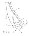
- Figure 1 illustrates in section a bead portion of a heavy load tire, for example, a tire for a bus or truck.
- the outer surface 20 and inner surface 22 of the tire are indicated to provide reference orientation.
- the bead portion includes a bead core 24, which in the illustrated embodiment is formed as a rectangularly profiled coil of steel wires. As known in the art, other profiles may be used for the bead core, including oval and circular.
- the bead portion mounts on a rim 50. Tension in the bead core 24 is transmitted to the rim by compression of the rubber between the bead core 24 and the rim seat 52 to secure the bead, and hence the tire, to the rim.
- the bead portion is shaped to have a seat face 26, a flattened region that engages the seat 52 of the rim 50.
- a reference seat point 28 near an outer end of the seat face 26 corresponds to a standardized reference point S on the rim.
- the Tire & Rim Association in its Yearbook publishes standard dimensions for rims, in which the reference point S locates a point on the rim at a nominal rim diameter and rim width.
- the two points 28 and S substantially coincide.
- the seat point 28 is not actually located on the tire bead; however, this point is easily identified by those skilled in the art, and is commonly used in specifying the mounted diameter and width of a tire.
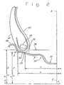
- the section of rim 50 shown in Figure 2 indicates the radius R and half width X rather than the diameter and width.
- the rim seat 52 is formed as a frustoconical section with respect to the axis of rotation A-A of the rim.
- the seat 52 forms a seat angle 56 of 15° with respect to the axis of rotation A-A.
- a 15° seat angle is used for rims for heavy load vehicles such as trucks and buses.
- the tire bead seat 26 ends at a tip 30 that represents a transition point where the end surface 32 of the bead curves away from the bead seat 26 to the inner surface 22 of the tire sidewall.
- the end surface 32 has a rounded shape in making the transition from the bead seat 26 to the inner surface 22 of the tire.
- Figure 3 shows a conventional bead 80 is illustrated mounted on a rim 50.
- the bead seat 82 of the conventional bead 80 is relatively longer and ends in a triangular shaped tip 84. Beads having this triangular tip, or bead toe, are common in the industry because it is believed that the elongated bead seat 82 ensures that a proper air-tight seal is formed.
- the longer bead seat 82 under the bead core 86 is believed to help stabilize the bead on the rim and help resist forces encountered when the vehicle is moving and turning and the wheels are rolling.
- the rim 50 includes a so-called drop center or well 54.
- the rim flange 58 is passed over the rim flange 58 and positioned in the well 54.
- the other side of the tire is then passed over the rim flange 58.
- the tire is then inflated to seat the beads on the rim seats.
- the opposite actions are performed.
- Forcing the beads over the rim flanges require a tool that deforms the tire bead, by twisting, bending and stretching it, to create sufficient clearance.
- the elongated, triangular bead toe 84 is difficult to move over the rim flange 58, even with a tool.
- the action of the tool and the forces imparted on the bead in passing over the flange can damage the bead toe, particularly in older tires, in which the rubber has oxidized and become brittle.
- the less resilient rubber can be cracked or broken.
- a broken bead toe can expose the bead, or result in the loss of integrity of the bead seat, either rendering the tire unfit for service.
- a tire bead could be securely seated and provide an air-tight seal with a rounded bead toe, thus eliminating the problems of the conventional bead toe.
- the short bead toe is easier to move over a rim flange, requiring less deformation, and therefore, is less subject to breaking.
- a bead in accordance with the invention requires less material and is thus, lighter in weight and less expensive to manufacture.
- a tire bead in accordance with the invention has a bead toe that includes a seat surface 26 ending in a transition point 30 and there joining an inner surface 32.
- An included angle 36 defined by the seat surface and a line T with origin at the transition point 30 and tangent to the inner surface 32 is in a range of 105° and 150°, inclusive. The included angle is measured in the direction that includes the bead toe. Preferably, the included angle 36 is in a range of 130° to 150°.
- the bead toe of the invention is also defined by the location of the transition point 30 relative to the seat point 28 or rim seat point S.
- the line Z-Z represents the equatorial plane, that is, the center of the rim and center of a mounted tire along the axis of rotation A-A.
- the nominal radius R of the rim is measured from the axis of rotation A-A.
- the axial distance X of the seat point S is half the nominal width, and is measured from the center line Z-Z of the rim.
- the nominal width and diameter for a rim of a particular size are published by the Tire & Rim Association in the Yearbook.
- the seat point S is defined for each standardized rim and the tires that fit on that rim, that is, the distances R and X can be calculated from standard data, and are useful as references.
- the transition point 30 is located relative to the rim seat point S when the tire is positioned with seat points 28 coinciding with point S as being at a radial distance P in a range of 0.95 R to 0.97 R. It is understood that the tire having two beads, for both seat points 28 to coincide with the reference rim seat points S, the tire would be positioned as if the tire were mounted on a rim. This may be accomplished by actually mounting the tire on an appropriate rim, or using a device that can establish the appropriate bead locations.
- transition point 30 is at an axial distance Y of at least 0.78 X.
- the transition point 30 is axially inward of the center of the bead core 24.
- the transition point 30, of course, cannot be at an axial distance from the tire center greater than that of the seat point S or 28.
- a tire in accordance with the invention can be manufactured using a mold specially adapted to form the bead toe.
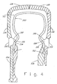
- Figure 4 is a highly simplified, sectional representation of a mold in accordance with the invention.
- the mold includes a membrane 100 that is filled with a heated fluid for transmitting pressure and heat to the interior of the tire.
- the ends 102 of the membrane 100 are clamped in upper 104 and lower 106 membrane plates.
- Upper 110 and lower 112 bead rings, upper 114 and lower 116 sidewall plates, and tread rings 118, 120 are mounted in the mold to form the exterior of the tire.
- a tire being cured in the mold will reside in a space 90 defined between the membrane 100 and the bead rings, sidewall plates and tread rings.
- the bead rings 110, 112 each include a conical ridge 124 defining a seat face 130 to shape the bead seat and a guide surface 132 to guide the membrane 100.
- the membrane 100 extends along the guide surface 132 around a point at the end of the seat face 130 to mold the bead toe of the tire.
- the point at the end of the seat face 130 corresponds to the transition point 30 of the tire bead toe (see Figures 1 and 2).
- the conical ridge 124 ensures that the transition point 30 of the tire bead is appropriately located.
- the guide surface 132 diverts the membrane 100 from a horizontal disposition at the clamped ends to bend toward the equatorial plane of the tire so that the seat face 130 and membrane 100 as it departs from the conical ridge 124 define an included angle in a range of 105° to 155°, and preferably, in a range of 130° to 150°. Accordingly, an included angle between the seat face 130 and the guide surface 132 is in a range of approximately 30° to 95°. Fluid pressure inside the membrane causes the membrane to curve around the tire bead and conform with the inner surface of the tire.
- a mold in accordance with the invention provides a better cure of the bead toe by eliminating empty space in the mold.
- the rubber does not have to first flow into the space, and accordingly, molding pressure on and heat transfer to the bead is equalized early in the molding process.
Landscapes
- Engineering & Computer Science (AREA)
- Mechanical Engineering (AREA)
- Tires In General (AREA)
- Moulds For Moulding Plastics Or The Like (AREA)
Claims (5)
- Pneu destiné à être monté sur une jante pourvue d'un siège conique à environ 15°, ledit pneu possédant deux bourrelets, un bourrelet de chaque côté d'un plan équatorial, chaque bourrelet présentant une face d'appui (26) de forme sensiblement tronconique et une surface intérieure (32), la face d'appui et la surface intérieure se rejoignant en un point de transition (30), caractérisé par le fait que la face d'appui et la surface intérieure définissent un angle au sommet (36) autour du point de transition dans une plage de 105° à 155°.
- Pneu selon la revendication 1, l'angle au sommet entre la face d'appui et la surface intérieure se situant dans une plage de 130° à 150°.
- Pneu selon la revendication 1 ou 2, l'invention comportant en outre la localisation du point de transition (30) à une distance radiale (P) d'un centre de rotation du pneu valant 0,95 à 0,97 fois une distance radiale (R) du point d'appui (S) par rapport au centre de rotation du pneu.
- Pneu selon l'une des revendications 1 à 3, l'invention comportant en outre la localisation du point de transition (30) à une distance axiale (Y) du plan équatorial valant au moins 0,78 fois, mais n'étant pas supérieure à, une distance axiale (X) du point d'appui (S) par rapport au plan équatorial.
- Moule de pneu pour charges lourdes, comportant :une membrane (100) destinée à former par moulage l'intérieur d'un pneu ;des plaques à membrane supérieure (104) et inférieure (106) destinées à pincer les extrémités libres de la membrane dans une position parallèle à un plan équatorial du moule ;des anneaux de bourrelet supérieur (110) et inférieur (112) montés radialement vers l'extérieur des plaques à membrane pour former par moulage les portions de bourrelets du pneu et pour guider la membrane des plaques à membrane vers l'intérieur du pneu, chaque anneau de bourrelet présentant une crête conique (124) définissant une surface formant siège (130) et une surface-guide (132) se rejoignant en un point, un angle au sommet formé entre la surface formant siège et un prolongement de la surface-guide au-delà du point se situant dans une plage de 105° à 155°.
Applications Claiming Priority (1)
| Application Number | Priority Date | Filing Date | Title |
|---|---|---|---|
| PCT/US1999/024447 WO2002032697A1 (fr) | 1999-10-18 | 1999-10-18 | Pneu a pointe de bourrelet arrondie et moule destine a former ce pneu |
Publications (2)
| Publication Number | Publication Date |
|---|---|
| EP1240033A1 EP1240033A1 (fr) | 2002-09-18 |
| EP1240033B1 true EP1240033B1 (fr) | 2006-10-04 |
Family
ID=22273858
Family Applications (1)
| Application Number | Title | Priority Date | Filing Date |
|---|---|---|---|
| EP99974269A Expired - Lifetime EP1240033B1 (fr) | 1999-10-18 | 1999-10-18 | Pneu a pointe de bourrelet arrondie et moule destine a former ce pneu |
Country Status (10)
| Country | Link |
|---|---|
| EP (1) | EP1240033B1 (fr) |
| JP (1) | JP2004511383A (fr) |
| KR (1) | KR100701447B1 (fr) |
| CN (1) | CN1202967C (fr) |
| AU (1) | AU2297802A (fr) |
| CA (1) | CA2355770C (fr) |
| DE (1) | DE69933482T2 (fr) |
| MX (1) | MXPA01006233A (fr) |
| RU (1) | RU2232682C2 (fr) |
| WO (1) | WO2002032697A1 (fr) |
Cited By (3)
| Publication number | Priority date | Publication date | Assignee | Title |
|---|---|---|---|---|
| US9108468B2 (en) | 2011-11-30 | 2015-08-18 | Michelin Recherche Et Technique S.A. | Tire bead mounting verification system |
| DE102016223026A1 (de) | 2016-11-22 | 2018-05-24 | Continental Reifen Deutschland Gmbh | Vorrichtung zum Vulkanisieren von Nutzfahrzeugreifen |
| DE102020215727A1 (de) | 2020-12-11 | 2022-06-15 | Continental Reifen Deutschland Gmbh | Nutzfahrzeugreifen |
Families Citing this family (6)
| Publication number | Priority date | Publication date | Assignee | Title |
|---|---|---|---|---|
| JP4952925B2 (ja) * | 2007-07-18 | 2012-06-13 | 横浜ゴム株式会社 | 空気入りタイヤの加硫成形方法及びその装置 |
| KR100987415B1 (ko) * | 2008-07-11 | 2010-10-12 | 한국건설기술연구원 | 조류발생실험장치 |
| JP5363217B2 (ja) * | 2009-07-01 | 2013-12-11 | 住友ゴム工業株式会社 | 更生タイヤ用モールド及びこれを用いた更生タイヤの製造方法 |
| JP6665530B2 (ja) | 2015-12-25 | 2020-03-13 | 横浜ゴム株式会社 | 空気入りタイヤ |
| DE102017222282A1 (de) | 2017-12-08 | 2019-06-13 | Continental Reifen Deutschland Gmbh | Nutzfahrzeugreifen |
| KR102463604B1 (ko) | 2021-02-15 | 2022-11-08 | 한국타이어앤테크놀로지 주식회사 | 다중 프로파일이 적용된 비드부 |
Family Cites Families (7)
| Publication number | Priority date | Publication date | Assignee | Title |
|---|---|---|---|---|
| NL125928C (fr) * | 1961-12-08 | |||
| FR2303677A2 (fr) * | 1975-03-13 | 1976-10-08 | Uniroyal | Procede de traitement d'une enveloppe de bandage pneumatique pour eviter le fluage des bandelettes d'usure des talons |
| US4057091A (en) * | 1976-04-07 | 1977-11-08 | The Firestone Tire & Rubber Company | Pneumatic tire |
| JPH01297310A (ja) * | 1988-05-24 | 1989-11-30 | Ohtsu Tire & Rubber Co Ltd :The | 空気入りタイヤ |
| SU1705132A1 (ru) * | 1990-06-08 | 1992-01-15 | Научно-исследовательский институт шинной промышленности | Покрышка пневматической шины |
| JPH0558120A (ja) * | 1991-08-29 | 1993-03-09 | Bridgestone Corp | 重荷重用チユーブレス空気入りラジアルタイヤ |
| US5464051A (en) * | 1993-11-05 | 1995-11-07 | The Goodyear Tire & Rubber Company | Radial ply tire with specified bead portion design |
-
1999
- 1999-10-18 DE DE69933482T patent/DE69933482T2/de not_active Expired - Lifetime
- 1999-10-18 WO PCT/US1999/024447 patent/WO2002032697A1/fr not_active Ceased
- 1999-10-18 CN CNB998146048A patent/CN1202967C/zh not_active Expired - Fee Related
- 1999-10-18 CA CA002355770A patent/CA2355770C/fr not_active Expired - Fee Related
- 1999-10-18 KR KR1020017007395A patent/KR100701447B1/ko not_active Expired - Fee Related
- 1999-10-18 EP EP99974269A patent/EP1240033B1/fr not_active Expired - Lifetime
- 1999-10-18 MX MXPA01006233A patent/MXPA01006233A/es not_active IP Right Cessation
- 1999-10-18 JP JP2002535906A patent/JP2004511383A/ja active Pending
- 1999-10-18 AU AU22978/02A patent/AU2297802A/en not_active Abandoned
- 1999-10-18 RU RU2001116562/11A patent/RU2232682C2/ru not_active IP Right Cessation
Cited By (5)
| Publication number | Priority date | Publication date | Assignee | Title |
|---|---|---|---|---|
| US9108468B2 (en) | 2011-11-30 | 2015-08-18 | Michelin Recherche Et Technique S.A. | Tire bead mounting verification system |
| DE102016223026A1 (de) | 2016-11-22 | 2018-05-24 | Continental Reifen Deutschland Gmbh | Vorrichtung zum Vulkanisieren von Nutzfahrzeugreifen |
| DE102016223026B4 (de) | 2016-11-22 | 2024-10-17 | Continental Reifen Deutschland Gmbh | Vorrichtung zum Vulkanisieren von Nutzfahrzeugreifen |
| DE102020215727A1 (de) | 2020-12-11 | 2022-06-15 | Continental Reifen Deutschland Gmbh | Nutzfahrzeugreifen |
| WO2022122092A1 (fr) | 2020-12-11 | 2022-06-16 | Continental Reifen Deutschland Gmbh | Pneu de véhicule utilitaire |
Also Published As
| Publication number | Publication date |
|---|---|
| RU2232682C2 (ru) | 2004-07-20 |
| WO2002032697A1 (fr) | 2002-04-25 |
| AU2297802A (en) | 2002-04-29 |
| CN1384788A (zh) | 2002-12-11 |
| DE69933482D1 (de) | 2006-11-16 |
| DE69933482T2 (de) | 2007-03-29 |
| KR20020039263A (ko) | 2002-05-25 |
| CA2355770C (fr) | 2009-01-13 |
| CN1202967C (zh) | 2005-05-25 |
| KR100701447B1 (ko) | 2007-03-30 |
| EP1240033A1 (fr) | 2002-09-18 |
| CA2355770A1 (fr) | 2001-04-18 |
| JP2004511383A (ja) | 2004-04-15 |
| MXPA01006233A (es) | 2002-06-21 |
Similar Documents
| Publication | Publication Date | Title |
|---|---|---|
| EP1240033B1 (fr) | Pneu a pointe de bourrelet arrondie et moule destine a former ce pneu | |
| US6357502B1 (en) | Tire wheel and its components | |
| JPH0761761B2 (ja) | チュ−ブレスラジアルタイヤ | |
| EP0922592B1 (fr) | Roue équippée d'un pneumatique et ses composants | |
| US20020046794A1 (en) | Assembly for mounting a tire on a hub | |
| CN102341254B (zh) | 用于重型车辆的轮胎 | |
| US5318088A (en) | Rim with inclined seats and assembly of such a rim with a tire | |
| US4274465A (en) | Pneumatic tire and wheel rim assembly | |
| US20010042582A1 (en) | Tire with rounded bead toe and a mold for forming the tire | |
| CN100423958C (zh) | 由轮胎和密封件构成的总成及其制造方法 | |
| EP3210801A1 (fr) | Pneumatique pour vehicule avec un bourrelet a contour ameliore | |
| EP0352140A2 (fr) | Pneumatique radial à parties de talons plus résistantes | |
| KR20030017605A (ko) | 개선된 구조의 비드를 가지는 타이어 | |
| US4732198A (en) | Vehicle wheel | |
| US2868258A (en) | Tubeless tire and rim therefor | |
| AU5197201A (en) | Tire with rounded bead toe and a mould for forming the tire | |
| US5203934A (en) | Pneumatic radial tire with high durable bead portions | |
| JP2002528332A (ja) | タイヤおよびリム組立体 | |
| US8109309B2 (en) | Tire with seats of unequal diameters and reverse axial offset in an inflated state | |
| US3674080A (en) | Wheel for high-speed cornering | |
| US20200198411A1 (en) | Tire with no ply turnup | |
| EP0715975A2 (fr) | Bandages pneumatiques pour poids-lourds-grande vitesse | |
| GB2245530A (en) | Pneumatic tyre and wheel assembly | |
| JP4252380B2 (ja) | タイヤ金型の設計方法、タイヤ金型およびタイヤの製造方法 | |
| GB2064446A (en) | Tyre and wheel rim assemblies |
Legal Events
| Date | Code | Title | Description |
|---|---|---|---|
| PUAI | Public reference made under article 153(3) epc to a published international application that has entered the european phase |
Free format text: ORIGINAL CODE: 0009012 |
|
| AK | Designated contracting states |
Kind code of ref document: A1 Designated state(s): AT BE CH CY DE DK ES FI FR GB GR IE IT LI LU MC NL PT SE |
|
| AX | Request for extension of the european patent |
Free format text: AL;LT;LV;MK;RO;SI |
|
| 17P | Request for examination filed |
Effective date: 20021025 |
|
| RBV | Designated contracting states (corrected) |
Designated state(s): DE ES FR GB IT |
|
| GRAP | Despatch of communication of intention to grant a patent |
Free format text: ORIGINAL CODE: EPIDOSNIGR1 |
|
| GRAS | Grant fee paid |
Free format text: ORIGINAL CODE: EPIDOSNIGR3 |
|
| GRAA | (expected) grant |
Free format text: ORIGINAL CODE: 0009210 |
|
| AK | Designated contracting states |
Kind code of ref document: B1 Designated state(s): DE ES FR GB IT |
|
| PG25 | Lapsed in a contracting state [announced via postgrant information from national office to epo] |
Ref country code: IT Free format text: LAPSE BECAUSE OF FAILURE TO SUBMIT A TRANSLATION OF THE DESCRIPTION OR TO PAY THE FEE WITHIN THE PRESCRIBED TIME-LIMIT;WARNING: LAPSES OF ITALIAN PATENTS WITH EFFECTIVE DATE BEFORE 2007 MAY HAVE OCCURRED AT ANY TIME BEFORE 2007. THE CORRECT EFFECTIVE DATE MAY BE DIFFERENT FROM THE ONE RECORDED. Effective date: 20061004 |
|
| REG | Reference to a national code |
Ref country code: GB Ref legal event code: FG4D |
|
| REF | Corresponds to: |
Ref document number: 69933482 Country of ref document: DE Date of ref document: 20061116 Kind code of ref document: P |
|
| PG25 | Lapsed in a contracting state [announced via postgrant information from national office to epo] |
Ref country code: ES Free format text: LAPSE BECAUSE OF FAILURE TO SUBMIT A TRANSLATION OF THE DESCRIPTION OR TO PAY THE FEE WITHIN THE PRESCRIBED TIME-LIMIT Effective date: 20070115 |
|
| ET | Fr: translation filed | ||
| PLBE | No opposition filed within time limit |
Free format text: ORIGINAL CODE: 0009261 |
|
| STAA | Information on the status of an ep patent application or granted ep patent |
Free format text: STATUS: NO OPPOSITION FILED WITHIN TIME LIMIT |
|
| 26N | No opposition filed |
Effective date: 20070705 |
|
| PGFP | Annual fee paid to national office [announced via postgrant information from national office to epo] |
Ref country code: GB Payment date: 20101013 Year of fee payment: 12 Ref country code: IT Payment date: 20101023 Year of fee payment: 12 |
|
| GBPC | Gb: european patent ceased through non-payment of renewal fee |
Effective date: 20121018 |
|
| PG25 | Lapsed in a contracting state [announced via postgrant information from national office to epo] |
Ref country code: GB Free format text: LAPSE BECAUSE OF NON-PAYMENT OF DUE FEES Effective date: 20121018 |
|
| PG25 | Lapsed in a contracting state [announced via postgrant information from national office to epo] |
Ref country code: IT Free format text: LAPSE BECAUSE OF NON-PAYMENT OF DUE FEES Effective date: 20121018 |
|
| REG | Reference to a national code |
Ref country code: FR Ref legal event code: PLFP Year of fee payment: 17 |
|
| PGFP | Annual fee paid to national office [announced via postgrant information from national office to epo] |
Ref country code: DE Payment date: 20151022 Year of fee payment: 17 |
|
| PGFP | Annual fee paid to national office [announced via postgrant information from national office to epo] |
Ref country code: FR Payment date: 20151023 Year of fee payment: 17 |
|
| REG | Reference to a national code |
Ref country code: DE Ref legal event code: R119 Ref document number: 69933482 Country of ref document: DE |
|
| REG | Reference to a national code |
Ref country code: FR Ref legal event code: ST Effective date: 20170630 |
|
| PG25 | Lapsed in a contracting state [announced via postgrant information from national office to epo] |
Ref country code: FR Free format text: LAPSE BECAUSE OF NON-PAYMENT OF DUE FEES Effective date: 20161102 Ref country code: DE Free format text: LAPSE BECAUSE OF NON-PAYMENT OF DUE FEES Effective date: 20170503 |