EP1240860A2 - Récipient de cuisson - Google Patents
Récipient de cuisson Download PDFInfo
- Publication number
- EP1240860A2 EP1240860A2 EP02251750A EP02251750A EP1240860A2 EP 1240860 A2 EP1240860 A2 EP 1240860A2 EP 02251750 A EP02251750 A EP 02251750A EP 02251750 A EP02251750 A EP 02251750A EP 1240860 A2 EP1240860 A2 EP 1240860A2
- Authority
- EP
- European Patent Office
- Prior art keywords
- lid
- hole
- cooking apparatus
- cooker body
- cooking
- Prior art date
- Legal status (The legal status is an assumption and is not a legal conclusion. Google has not performed a legal analysis and makes no representation as to the accuracy of the status listed.)
- Granted
Links
Images


Classifications
-
- A—HUMAN NECESSITIES
- A47—FURNITURE; DOMESTIC ARTICLES OR APPLIANCES; COFFEE MILLS; SPICE MILLS; SUCTION CLEANERS IN GENERAL
- A47J—KITCHEN EQUIPMENT; COFFEE MILLS; SPICE MILLS; APPARATUS FOR MAKING BEVERAGES
- A47J36/00—Parts, details or accessories of cooking-vessels
- A47J36/06—Lids or covers for cooking-vessels
- A47J36/08—Lids or covers for cooking-vessels for draining liquids from vessels
Definitions
- the present invention relates to a lid for a cooking vessel having an upper side and a lower side for covering a cooking vessel.
- cooking vessels such as conventional rice cookers and cooking pots which are used in cooking rice or making stew.
- These conventional cooking vessels are generally comprised of a cylindrical body for holding the food to be cooked and a lid.
- a user first puts the food to be cooked into the body, covers the body with the lid, puts the cooker on a gas range or in a microwave oven and applies heat.
- a lid according to the present invention is characterised by a recess on said upper side and an aperture extending between said recess and said lower side so as to provide a communication path to the inside of a vessel closed by the lid.
- the recess may be defined by a central conical projection and an outwardly sloping wall surface about the conical projection.
- the conical projection is capped by a cap and the path comprises an opening in the apex of the conical projection and a radial aperture through a wall of the cap.
- the centre of the conical portion is depressed and a hole formed through the lid at the bottom of the depressed centre of the conical portion.
- the recess may comprise the inside of a cup projecting from the top of the lid.
- the cup and said aperture may constitute a funnel-like structure.
- the lid may be domed and have a recess in its lower side, and the base of the cup may project into the recess in the lower side of the lid.
- said aperture extends between the centre of the inside of the bottom of the cup and the recess in the lower side of the lid and is accompanied by a further aperture to one side and extending between the inside of the bottom of the cup and the recess in the lower side of the lid.
- a cooking vessel including a pot and a lid according to the present invention.
- the lid may have an annular projection configured to be received snugly in the opening of the pot.
- the pot and the lid have complementary ring-shaped faces which abut each other when the lid is on the pot. More preferably, complementary channels are formed in said ring-shaped faces for receiving a sealing ring.
- the lid is configured to rest upon the rim of the pot in use and a sealing member is affixed to the lower face of the lid to provide a seal between the lid and rim of the pot.
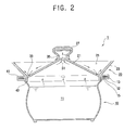
- a cooking vessel 1 comprises a cylindrical body 10, open at the top to provide access to an internal space 11 for placing food to be cooked therein, and a lid 20 for closing the vessel 1.
- a circumferential, lower flange 12 projects from the top of the body 10.
- On the upper face of the lower flange 12 is formed a channel-shaped engagement part 13.
- the engagement part 13 of the lower flange 12 receives a ring-shape sealing member 15 made of heat-resistant rubber.
- the body 10 may be made, e.g. by moulding, from metal or glass which are excellent materials for withstanding heat.
- the lid 20 has a central conical part 21 projecting upwards and a peripheral wall 23 projecting upwards and outwards from base of the conical part 21.
- a channel is formed between the wall 23 and the conical part 21 and serves as a collector part 25 for collecting condensation.
- An upper hole 31 is formed at the top of the conical part 21 and one or more lower holes 33 are formed in the collector part 25.
- a cap 27 is mounted over the upper hole 31.
- the cap 27 has a cylindrical side wall, in which there is at least one guide hole 35 directed toward the collector part 25.
- the cap 27 is coupled to the lid 20 by screws 32.
- the cap 27 may be coupled to the lid 20 using a variety of methods, for example, a complementary projection and groove.
- An upper flange 41 for closely contacting the lower flange 12, is formed around the bottom of the lid 20.
- An annular projection 43 projects downwards from the bottom of the lid 20 and fits into the opening of the body 10.
- the bottom face of the upper flange 41 and the top face of the lower flange 12 may be finished by polishing so as to allow them to be in close contact with each other.
- the lid 20 Since the projection 43 is fitted into the opening of the body 10 when the vessel is closed by the lid 20, the movement of the lid 20 during cooking is prevented. To more effectively prevent the movement of the lid 20 due to the pressure formed within the body 10, the lid 20 is manufactured to have an appropriate weight.
- the steam and water passing through the upper and lower holes 31, 33 are discharged rapidly due to the high pressure formed within the body 10.
- the steam and water discharged through the upper through hole 31 are prevented from dissipating into the air because of the cap 27, and the steam and water discharged through the lower holes 33 are dispersed within the collector part 25, thereby lowering the force with which they are discharged.
- the condensed water discharged through the upper and lower holes 31, 33 moves downward along the inclined wall side of the collector part 25 formed by the conical part 21 and the outer wall 23, and then flows back into the body 10 through the lower holes 33.
- the generation of the over-pressure within the body 10 and the dissipation of the condensed water into the air are both prevented.
- the lid 20 will remain in its clogged state until the force on the lid due to the pressure in the body 10 reaches the weight of the lid 20.
- this force increases to exceed the weight of the lid 20
- the lid 20 is lifted up and down from the body 10 due to the over pressure within the body 10.
- the lid 20 is lifted so as not to be separated from the body 10, owing to the projection 43 formed at the bottom of the lid 20.
- the over-pressure within the body 10 is decreased.
- the lid closes the upper opening of the body 10 by its own weight.
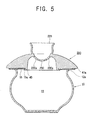
- a second cooking vessel has an elevated part 121 whose central portion is depressed downwards. Accordingly, the bottom face of the collector part 125 is constructed to have a plurality of valleys. On the bottom part of each valley are formed a plurality of holes 130 communicating the inside of the body 10 with the collector part 125.
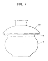
- a third cooking vessel 10 has a funnel-shaped collector part 225 formed in the central part of a convex lid 220.
- a single through hole 230 communicating the inside of the body 10 with the collector part 225 opens through the bottom of the collecting part 25.
- a fourth cooking vessel is similar to the third cooking vessel shown in Figure 4. However, around the central hole 230 is provided a plurality of auxiliary holes 230a and the lower face 41a of the lid 220 is in indirect contact with the lip 12a of the body 10. Also, a sealing member 15 is provided with a protruding part 15a placed between a projection 43 on the lower face 41a of the lid 220 and the lip 12a of the body 10 and is mounted to the lower face 41a of the lid 220.
- the collector part 225 communicating with the inside of the body 10 and formed in the lid 220, allows the steam generated within the body 10 to be discharged appropriately and condensed water to be collected back into the body 10, thereby preventing generation of over-pressure within the body and maintaining the pressure within the body 10 at an appropriate level. Further, boiling over of the food and dissipation of the steam and condensed water is prevented.
- the lifting up and down of the lid is prevented and the pressure within the body is properly maintained, thereby enhancing the taste and quality of the cooked rice.
- This is achieved by providing a cooking vessel capable of properly discharging the steam generated with the body during cooking and collecting the condensed water back into the body.
Landscapes
- Engineering & Computer Science (AREA)
- Food Science & Technology (AREA)
- Cookers (AREA)
Applications Claiming Priority (4)
| Application Number | Priority Date | Filing Date | Title |
|---|---|---|---|
| KR2001012941 | 2001-03-13 | ||
| KR20010012941 | 2001-03-13 | ||
| KR2002005711 | 2002-01-31 | ||
| KR10-2002-0005711A KR100448192B1 (ko) | 2001-03-13 | 2002-01-31 | 조리용기 |
Publications (3)
| Publication Number | Publication Date |
|---|---|
| EP1240860A2 true EP1240860A2 (fr) | 2002-09-18 |
| EP1240860A3 EP1240860A3 (fr) | 2003-10-01 |
| EP1240860B1 EP1240860B1 (fr) | 2007-11-14 |
Family
ID=36691540
Family Applications (1)
| Application Number | Title | Priority Date | Filing Date |
|---|---|---|---|
| EP02251750A Expired - Lifetime EP1240860B1 (fr) | 2001-03-13 | 2002-03-12 | Récipient de cuisson |
Country Status (5)
| Country | Link |
|---|---|
| US (1) | US20020129714A1 (fr) |
| EP (1) | EP1240860B1 (fr) |
| JP (1) | JP3958601B2 (fr) |
| CN (1) | CN1248630C (fr) |
| DE (1) | DE60223436D1 (fr) |
Families Citing this family (25)
| Publication number | Priority date | Publication date | Assignee | Title |
|---|---|---|---|---|
| US7073498B2 (en) * | 2003-04-09 | 2006-07-11 | Sylmark Holdings Limited | Combination steamer cone, rim and tray |
| USD521796S1 (en) * | 2004-03-18 | 2006-05-30 | Progressive International Corp. | Microwave popcorn popper |
| US8739692B2 (en) * | 2008-02-26 | 2014-06-03 | Restaurant Technology, Inc. | Chicken ring cooking device and method |
| DE102009041866C5 (de) * | 2009-09-17 | 2013-08-22 | Armin Harecker | Kochgefäßaufsatz zum Verhüten des Überkochens von Flüssigkeiten |
| KR101321129B1 (ko) * | 2011-03-03 | 2013-10-23 | 오재탁 | 넘침 방지용 냄비 뚜껑 |
| US20120222562A1 (en) * | 2011-03-04 | 2012-09-06 | Gaffar Mohammed | Food Steamer |
| US8590728B1 (en) * | 2012-02-28 | 2013-11-26 | Mamc, Llc | Boil-tolerant cookware |
| US20140021314A1 (en) * | 2012-07-23 | 2014-01-23 | Matthew Bourlier | Accessory support ring for an outdoor cooking vessel |
| DE102014115649A1 (de) * | 2014-10-28 | 2016-04-28 | Vorwerk & Co. Interholding Gmbh | Garaufsatz für ein aufheizbares Gefäß einer Küchenmaschine |
| USD802980S1 (en) * | 2015-10-06 | 2017-11-21 | Nostalgia Products Llc | Popcorn machine with canopy |
| JP6301304B1 (ja) * | 2015-12-04 | 2018-03-28 | 正義 高野 | 鍋蓋及び蓋付き鍋 |
| USD850847S1 (en) * | 2016-02-01 | 2019-06-11 | Gowanus Kitchen Lab, Llc | Cooking splatter device |
| JP5991776B1 (ja) * | 2016-05-26 | 2016-09-14 | 株式会社G・C | 蒸し鍋 |
| CN105919412A (zh) * | 2016-07-14 | 2016-09-07 | 天津市康利厨具制造有限公司 | 一种新型可视汤锅 |
| CN107713774B (zh) * | 2016-08-11 | 2020-06-05 | 佛山市顺德区美的电热电器制造有限公司 | 用于烹饪器具的蒸汽阀和具有其的烹饪器具 |
| JP2018061711A (ja) * | 2016-10-13 | 2018-04-19 | 正義 高野 | 調理鍋及び調理鍋システム |
| CN109984615B (zh) * | 2017-12-29 | 2024-04-05 | 南京卓鑫发科技有限公司 | 一种户外用防溢锅 |
| USD871130S1 (en) * | 2018-03-02 | 2019-12-31 | Gowanus Kitchen Lab, Llc | Frywall structure |
| JP7023749B2 (ja) * | 2018-03-09 | 2022-02-22 | シャープ株式会社 | 調理器 |
| JP7144211B2 (ja) * | 2018-06-25 | 2022-09-29 | 株式会社アイホー | 炊飯釜 |
| CN110332352A (zh) * | 2019-07-25 | 2019-10-15 | 路达(厦门)工业有限公司 | 一种水龙头 |
| WO2021021530A1 (fr) * | 2019-07-26 | 2021-02-04 | Bauer Sara Elizabeth | Élément de couverture pour le bord d'un autocuiseur électrique |
| CN114246463A (zh) * | 2020-09-25 | 2022-03-29 | 九阳股份有限公司 | 一种均匀加热的烹饪器具 |
| JP7745420B2 (ja) * | 2021-10-21 | 2025-09-29 | リンナイ株式会社 | 加熱調理容器 |
| CN114587152A (zh) * | 2022-03-30 | 2022-06-07 | 沃森供应链管理(广东)有限公司 | 一种适用高温高压加热的盖体结构 |
Family Cites Families (6)
| Publication number | Priority date | Publication date | Assignee | Title |
|---|---|---|---|---|
| US504243A (en) * | 1893-08-29 | Cooking utensil | ||
| US1188697A (en) * | 1915-01-23 | 1916-06-27 | Israel Steinberg | Safety-cover for culinary vessels. |
| US2385594A (en) * | 1944-01-25 | 1945-09-25 | Jr William F Witte | Utensil cover |
| US3809064A (en) * | 1972-07-11 | 1974-05-07 | Kanfer H | Vessel cover |
| US4482077A (en) * | 1982-11-23 | 1984-11-13 | Henderson Henning M | Perforated cover assembly |
| DE3505630C1 (de) * | 1985-02-19 | 1986-08-21 | Karl J. 7000 Stuttgart Speker | Abdeckhaube fuer Brat- und Kochgeraetschaften |
-
2002
- 2002-02-19 JP JP2002042293A patent/JP3958601B2/ja not_active Expired - Fee Related
- 2002-03-12 EP EP02251750A patent/EP1240860B1/fr not_active Expired - Lifetime
- 2002-03-12 DE DE60223436T patent/DE60223436D1/de not_active Expired - Lifetime
- 2002-03-12 CN CNB021032769A patent/CN1248630C/zh not_active Expired - Fee Related
- 2002-03-12 US US10/095,043 patent/US20020129714A1/en not_active Abandoned
Also Published As
| Publication number | Publication date |
|---|---|
| EP1240860A3 (fr) | 2003-10-01 |
| JP2002330863A (ja) | 2002-11-19 |
| CN1375257A (zh) | 2002-10-23 |
| DE60223436D1 (de) | 2007-12-27 |
| US20020129714A1 (en) | 2002-09-19 |
| CN1248630C (zh) | 2006-04-05 |
| EP1240860B1 (fr) | 2007-11-14 |
| JP3958601B2 (ja) | 2007-08-15 |
Similar Documents
| Publication | Publication Date | Title |
|---|---|---|
| EP1240860A2 (fr) | Récipient de cuisson | |
| KR100645981B1 (ko) | 전자렌지 조리용 시스템용기 | |
| JP3150132B2 (ja) | 料理道具の蓋・取っ手組立体 | |
| JP5181262B1 (ja) | 電子レンジ用圧力鍋 | |
| CA1287499C (fr) | Ustensile de cuisson | |
| CN110584498B (zh) | 防滴水锅盖及烹饪器皿 | |
| CN1404368A (zh) | 用蒸汽慢速烹饪的用具 | |
| KR20080001443U (ko) | 넘침방지 기능을 갖춘 조리기구용 뚜껑 | |
| US20040200841A1 (en) | Cookware lid | |
| KR101433097B1 (ko) | 조리용 진공냄비 | |
| KR100448192B1 (ko) | 조리용기 | |
| JPH0423451Y2 (fr) | ||
| WO2010049942A1 (fr) | Cuit-vapeur micro-ondes | |
| EP1813176B1 (fr) | Couvercle pour casseroles, poêles et produits similaires | |
| CN217696129U (zh) | 一种可调节排气量的锅体结构 | |
| KR102523956B1 (ko) | 자동압력조절모듈이 장착된 내솥 뚜껑을 구비한 전기밥솥 | |
| CN217937962U (zh) | 一种炸篮组件 | |
| KR20250083759A (ko) | 조리용기용 비산물 확산방지덮개 | |
| AU2004203486B2 (en) | Container for microwave oven cooking | |
| KR200357102Y1 (ko) | 압력밥솥 | |
| CN208864049U (zh) | 蒸笼盖、蒸笼组件和烹饪厨具 | |
| JP3100934U (ja) | ガス煮炊き用の釜 | |
| MXPA04002453A (es) | Tapa para utensilio de cocina. | |
| CN116898281A (zh) | 具有逸出控制的烹饪设备 | |
| KR20190109810A (ko) | 직화 구이냄비 |
Legal Events
| Date | Code | Title | Description |
|---|---|---|---|
| PUAI | Public reference made under article 153(3) epc to a published international application that has entered the european phase |
Free format text: ORIGINAL CODE: 0009012 |
|
| AK | Designated contracting states |
Kind code of ref document: A2 Designated state(s): AT BE CH CY DE DK ES FI FR GB GR IE IT LI LU MC NL PT SE TR |
|
| AX | Request for extension of the european patent |
Free format text: AL;LT;LV;MK;RO;SI |
|
| PUAL | Search report despatched |
Free format text: ORIGINAL CODE: 0009013 |
|
| AK | Designated contracting states |
Kind code of ref document: A3 Designated state(s): AT BE CH CY DE DK ES FI FR GB GR IE IT LI LU MC NL PT SE TR |
|
| AX | Request for extension of the european patent |
Extension state: AL LT LV MK RO SI |
|
| RIC1 | Information provided on ipc code assigned before grant |
Ipc: 7A 47J 27/56 B Ipc: 7A 47J 36/38 A |
|
| 17P | Request for examination filed |
Effective date: 20040207 |
|
| AKX | Designation fees paid |
Designated state(s): DE ES FR GB IT |
|
| RAP1 | Party data changed (applicant data changed or rights of an application transferred) |
Owner name: SAMSUNG ELECTRONICS CO., LTD. |
|
| 17Q | First examination report despatched |
Effective date: 20050906 |
|
| 17Q | First examination report despatched |
Effective date: 20050906 |
|
| GRAP | Despatch of communication of intention to grant a patent |
Free format text: ORIGINAL CODE: EPIDOSNIGR1 |
|
| GRAS | Grant fee paid |
Free format text: ORIGINAL CODE: EPIDOSNIGR3 |
|
| GRAA | (expected) grant |
Free format text: ORIGINAL CODE: 0009210 |
|
| AK | Designated contracting states |
Kind code of ref document: B1 Designated state(s): DE ES FR GB IT |
|
| REG | Reference to a national code |
Ref country code: GB Ref legal event code: FG4D |
|
| REF | Corresponds to: |
Ref document number: 60223436 Country of ref document: DE Date of ref document: 20071227 Kind code of ref document: P |
|
| PG25 | Lapsed in a contracting state [announced via postgrant information from national office to epo] |
Ref country code: ES Free format text: LAPSE BECAUSE OF FAILURE TO SUBMIT A TRANSLATION OF THE DESCRIPTION OR TO PAY THE FEE WITHIN THE PRESCRIBED TIME-LIMIT Effective date: 20080225 |
|
| PGFP | Annual fee paid to national office [announced via postgrant information from national office to epo] |
Ref country code: GB Payment date: 20080227 Year of fee payment: 7 |
|
| EN | Fr: translation not filed | ||
| PLBE | No opposition filed within time limit |
Free format text: ORIGINAL CODE: 0009261 |
|
| STAA | Information on the status of an ep patent application or granted ep patent |
Free format text: STATUS: NO OPPOSITION FILED WITHIN TIME LIMIT |
|
| 26N | No opposition filed |
Effective date: 20080815 |
|
| PG25 | Lapsed in a contracting state [announced via postgrant information from national office to epo] |
Ref country code: DE Free format text: LAPSE BECAUSE OF FAILURE TO SUBMIT A TRANSLATION OF THE DESCRIPTION OR TO PAY THE FEE WITHIN THE PRESCRIBED TIME-LIMIT Effective date: 20080215 Ref country code: FR Free format text: LAPSE BECAUSE OF FAILURE TO SUBMIT A TRANSLATION OF THE DESCRIPTION OR TO PAY THE FEE WITHIN THE PRESCRIBED TIME-LIMIT Effective date: 20080829 |
|
| GBPC | Gb: european patent ceased through non-payment of renewal fee |
Effective date: 20090312 |
|
| PG25 | Lapsed in a contracting state [announced via postgrant information from national office to epo] |
Ref country code: GB Free format text: LAPSE BECAUSE OF NON-PAYMENT OF DUE FEES Effective date: 20090312 |
|
| PG25 | Lapsed in a contracting state [announced via postgrant information from national office to epo] |
Ref country code: IT Free format text: LAPSE BECAUSE OF NON-PAYMENT OF DUE FEES Effective date: 20080331 |