EP1240967A2 - Port-outil pour des fraises à tailler annulaire les roues coniques à denture helicoidale et fraise à tailler - Google Patents
Port-outil pour des fraises à tailler annulaire les roues coniques à denture helicoidale et fraise à tailler Download PDFInfo
- Publication number
- EP1240967A2 EP1240967A2 EP02005463A EP02005463A EP1240967A2 EP 1240967 A2 EP1240967 A2 EP 1240967A2 EP 02005463 A EP02005463 A EP 02005463A EP 02005463 A EP02005463 A EP 02005463A EP 1240967 A2 EP1240967 A2 EP 1240967A2
- Authority
- EP
- European Patent Office
- Prior art keywords
- cutter head
- bar
- face
- rod
- milling spindle
- Prior art date
- Legal status (The legal status is an assumption and is not a legal conclusion. Google has not performed a legal analysis and makes no representation as to the accuracy of the status listed.)
- Granted
Links
Images


Classifications
-
- B—PERFORMING OPERATIONS; TRANSPORTING
- B23—MACHINE TOOLS; METAL-WORKING NOT OTHERWISE PROVIDED FOR
- B23F—MAKING GEARS OR TOOTHED RACKS
- B23F23/00—Accessories or equipment combined with or arranged in, or specially designed to form part of, gear-cutting machines
- B23F23/12—Other devices, e.g. tool holders; Checking devices for controlling workpieces in machines for manufacturing gear teeth
- B23F23/1237—Tool holders
- B23F23/125—Face mill holders
-
- B—PERFORMING OPERATIONS; TRANSPORTING
- B23—MACHINE TOOLS; METAL-WORKING NOT OTHERWISE PROVIDED FOR
- B23F—MAKING GEARS OR TOOTHED RACKS
- B23F21/00—Tools specially adapted for use in machines for manufacturing gear teeth
- B23F21/12—Milling tools
- B23F21/22—Face-mills for longitudinally-curved gear teeth
- B23F21/223—Face-mills for longitudinally-curved gear teeth with inserted cutting elements
- B23F21/226—Face-mills for longitudinally-curved gear teeth with inserted cutting elements in exchangeable arrangement
-
- B—PERFORMING OPERATIONS; TRANSPORTING
- B23—MACHINE TOOLS; METAL-WORKING NOT OTHERWISE PROVIDED FOR
- B23F—MAKING GEARS OR TOOTHED RACKS
- B23F23/00—Accessories or equipment combined with or arranged in, or specially designed to form part of, gear-cutting machines
- B23F23/12—Other devices, e.g. tool holders; Checking devices for controlling workpieces in machines for manufacturing gear teeth
- B23F23/1206—Tool mountings
Definitions
- the invention relates to a tool holder for rod cutter heads axial guide bore and with the bar cutter head predominantly in Bar knives penetrating the axial direction consisting of on the milling spindle located guide and coupling elements, namely a die guide the axial guide bore of the bar cutter head without play Shank, one facing the rod cutter head and axially supporting it End face, a driver for transmission of the drive torque the milling spindle on the rod cutter head and one the rod cutter head central clamping head pressing axially against the end face.
- the object of the present invention is a suitable tool holder and to propose a rod cutter head that enables the change of the rod cutter heads generally easier and with a single rod cutter head for both working and rotating directions for to enable milling.
- the assembly of a cutter head is also supposed to simple means and be possible in a short time.
- the tool holder is designed so that it protrudes into an area where the use of a symmetrical rod head is possible.
- the shaft attached to the milling spindle engages under the protruding ones Rod knife shafts.
- An outer face supports this Tool also reliable in the axial direction if the radius, on which the bar knives are arranged is chosen to be relatively small.
- the modification of the invention according to claim 2 allows by the Use of an adapter conventional universal milling spindles to use and guiding and driving the cutter head in one to realize axial area where a symmetrical formation of the Rod cutter head can be guaranteed.
- Independent claim 4 defines a further basic solution for the task at the beginning.
- the axial and radial guidance of the bar cutter head by guiding and Coupling elements realized, all of the shaft ends of the bar knife under attack.
- a separate guard ring is provided that attaches to the milling spindle is.
- Independent claim 5 defines the rod cutter head that can be used for the first time, which consists of an annular base body, and whose cross-section is symmetrical about a radial axis can be.
- the dimensional modification of the cutter head according to claim 6 ensures on the one hand, an optimal tension of the bar knives and guaranteed also regardless of the intended use (right-hand operation or Left hand operation) a reliable connection with the clutch and Guide elements for the milling spindle and / or the adapter.
- the design of the rod cutter head according to claim 7 also enables the use of rod cutter heads with both very large and very small diameters of the rod mass circles. If the diameter of the bar knife circle is very large, the bar knife head is guided axially very far outside. This increases the precision of his way of working, especially with large cutting forces. On the other hand, the bar knives can be arranged on very small radii in this embodiment. The axial support of the tool does not require any special means within the bar knife.
- the arrangement of the driver in the area of the outer end faces of the Rod cutter head - according to claim 8 - leads to a lower load the same or to increase the torque to be transmitted.
- the design of the bar cutter head according to claim 9 allows it to be easily detached from the adapter or from the milling spindle.
- the use of the cover plate according to claim 10 enables gentle and safe transport of the prepared cutter heads.
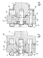
- This milling spindle 1 describes a preferred embodiment of the tool holder using a conventional milling spindle 1.
- This milling spindle 1 has an axially protruding for the radial guidance of the adapter 2 Shank 12, an end face 11 for axial guidance and for transmission of the torque a driver 13, the screw connection is held in a collar of the milling spindle 1.
- Adapter 2 placed axially.
- This adapter 2 has one for this purpose Guide bore 27, an end face 26 and a recess 28 for the driver 13.
- To secure these leading and coupling Connection between adapter 2 and milling spindle 1 are several clamping screws 14 provided the corresponding holes 29 in the adapter 2 reach through.
- the adapter 2 has on the side facing the rod cutter head 3 is coupling and guide elements that extend into the axial Clamping range 38 of the rod cutter head 3 range, in which the Guide and clamping elements (clamping wedges 36) for the bar knife 35 are located.
- the clamping elements for the bar knife 35 exist in the present Case of wedges 36, which the semicircular shafts of Bar knife 35 in corresponding recesses of the bar knife head lead and clamp.
- the position of the clamping wedges 36 in the clamping area 38 is secured in the axial direction by the fixing screws 361.
- the clamping action of the clamping wedges 36 brings the clamping screws 37 on.
- the shaft 22 of the adapter 2 extends into a guide bore 32 of the Rod cutter head 3. This guide bore 32 is in the axial Clamping area 38 of the bar knife 35.
- the shaft 22 can be slightly conical be designed so that the connection between adapter 2 and rod cutter head 3 can be guaranteed without play in the radial direction.
- the adapter 2 also has an end face 21 on which the adjacent End face 31, 31 'of the rod cutter head 3 can securely create.
- this end face 21 is located within the path of the bar knife 35. Another part is the rod knife 35 outside the path arranged. Is located between these two parts of the end face 21 there is an annular space 25 in which the rear ends of the bar knife protrude.
- a groove 232 incorporated in this groove 232 is a Driver 23 held by screw 231. This driver 23 engages into a corresponding recess (groove 33) on the rod cutter head 3 almost free of play.
- the rod cutter head 3 is symmetrical. He owns the on both sides radial axis 30 guide bores 32, 32 'in the central area be separated from each other by the collar 34. The outside each lying boundary surface of the federal government serves to attack the clamping head 24th
- the rod cutter head 3 has symmetrical on both sides of the axis 30 mutually arranged guide and coupling elements, so that the Rod cutter head 30 for the purpose of changing its working direction, after the release of the adapter 2, only about the radial axis 30 by 180 ° must be pivoted. This pivoting changes the Direction of inclination of the clamping surface of the bar knife 35, so that from the so-called Right-hand operation can be switched to left-hand operation, without using a differently designed bar cutter head 3.
- a pin 242 is attached, which is in a central threaded hole of the adapter 2 engages and is reliably and precisely fixed therein.
- the rod cutter head 3 receives through the Pin 242 an additional radial guide, which is mainly the assembly of the cutter head.
- An outer threaded section on Pin 242 receives the clamping nut 241.
- the clamping nut 241 has an axially projecting section with corresponding Key faces and a radially outward facing Collar with a larger diameter in the outer guide hole 32 of the bar cutter head 3 place.
- a cover plate 4 on the outer End face 31 'of the rod cutter head 3 attached.
- This cover plate 4 has at least one protrusion 42 inside the collar of the Clamping nut 241 overlaps. Because this cover plate 4 by means of fastening screws 41 is stably attached to the rod cutter head 3, can very large, lifting tensile forces by means of the clamping screw 241 the rod cutter head 3 are exercised.
- the cover plate 4 can additionally be equipped with a profile that the sharp-edged Heads of the bar knife 35 overlaps. During transportation and Storage are then reliably protected. Before dismantling the Bar cutter head 3 of the adapter 2, the cover plate 4 in a first operation by means of the fastening screws 41.
- a tool holder in which the coupling and Guide elements of the milling spindle 1 'are designed so that they Tasks of the adapter 2 that has been described with reference to FIG. 1 can take over with. That is, the shaft 12 'of the milling spindle 1' the rod knife 35 extends into the axially defined clamping range 38.
- the end face 11 'for axially fixing a symmetrically formed Bar knife head 3 extends over the area of the bar knife and extends symmetrically into the area of the end faces 31, 31 ' trained rod cutter head 3.
- the clamping head 24 is on the same Effective as described with reference to FIG. 1.
- the pin 242 is inserted directly into a corresponding one Threaded hole of the milling spindle 1 'screwed in.
- FIG. 6 describes an embodiment similar to FIG. 5. Also in this case, the milling spindle 1 "takes over the function of the adapter 2.
- the Coupling and guide elements for the rod cutter head 3 are here all arranged within the path of the bar knife 35.
- the shaft 12 "of the milling spindle 1" protrudes in the axial direction up to the clamping area 38 the bar knife 35.
- the axial support of the bar knife head 3 takes place here solely through the end face 11 "of the milling spindle 1".
- the driver 13 is arranged in the region of this end face 11" and engages in corresponding grooves or recesses on the symmetrical trained knife head 3 ".
- a protective ring 15 on the milling spindle 1 " is in this case a protective ring 15 on the milling spindle 1 ".
- the protective ring 15 overlaps the free space End sections of the bar knife 35 and thus avoids accidents and reduces pollution.
- the guard ring 15 has no guide or here Clutch performance.
Landscapes
- Engineering & Computer Science (AREA)
- Mechanical Engineering (AREA)
- Milling Processes (AREA)
- Turning (AREA)
- Cutting Tools, Boring Holders, And Turrets (AREA)
Applications Claiming Priority (2)
| Application Number | Priority Date | Filing Date | Title |
|---|---|---|---|
| DE10112729A DE10112729B4 (de) | 2001-03-14 | 2001-03-14 | Werkzeughalter mit ringförmigem Stabmesserkopf |
| DE10112729 | 2001-03-14 |
Publications (3)
| Publication Number | Publication Date |
|---|---|
| EP1240967A2 true EP1240967A2 (fr) | 2002-09-18 |
| EP1240967A3 EP1240967A3 (fr) | 2004-01-02 |
| EP1240967B1 EP1240967B1 (fr) | 2007-12-12 |
Family
ID=7677742
Family Applications (1)
| Application Number | Title | Priority Date | Filing Date |
|---|---|---|---|
| EP02005463A Expired - Lifetime EP1240967B1 (fr) | 2001-03-14 | 2002-03-09 | Port-outil pour des fraises à tailler annulaire les roues coniques à denture helicoidale et fraise à tailler |
Country Status (3)
| Country | Link |
|---|---|
| EP (1) | EP1240967B1 (fr) |
| AT (1) | ATE380620T1 (fr) |
| DE (2) | DE10112729B4 (fr) |
Family Cites Families (5)
| Publication number | Priority date | Publication date | Assignee | Title |
|---|---|---|---|---|
| GB649538A (en) * | 1947-02-08 | 1951-01-31 | Oerlikon Buehrle Ag | Improvements in or relating to cutters for cutting curved tooth gear wheels |
| GB972365A (en) * | 1962-10-08 | 1964-10-14 | Gleason Works | Improvements relating to apparatus for cutting gears and the like |
| US3571876A (en) * | 1968-10-21 | 1971-03-23 | Gleason Works | Means for mounting blades in a cutter |
| DD132935A1 (de) * | 1977-02-02 | 1978-11-22 | Anton Hipp | Stirnfraeskopf mit stabartigen fraesmeisseln |
| EP1071533B1 (fr) * | 1998-02-11 | 2004-04-07 | The Gleason Works | Outil de coupe permettant de produire des articles dentes |
-
2001
- 2001-03-14 DE DE10112729A patent/DE10112729B4/de not_active Expired - Fee Related
-
2002
- 2002-03-09 EP EP02005463A patent/EP1240967B1/fr not_active Expired - Lifetime
- 2002-03-09 AT AT02005463T patent/ATE380620T1/de not_active IP Right Cessation
- 2002-03-09 DE DE50211334T patent/DE50211334D1/de not_active Expired - Fee Related
Also Published As
| Publication number | Publication date |
|---|---|
| ATE380620T1 (de) | 2007-12-15 |
| EP1240967A3 (fr) | 2004-01-02 |
| DE10112729A1 (de) | 2002-10-02 |
| DE10112729B4 (de) | 2007-01-18 |
| DE50211334D1 (de) | 2008-01-24 |
| EP1240967B1 (fr) | 2007-12-12 |
Similar Documents
| Publication | Publication Date | Title |
|---|---|---|
| EP2032295B1 (fr) | Point de séparation entre deux éléments partiels d'un système d'outil rotatif | |
| DE60202138T2 (de) | Stumpfschleifscheibe und schneidanordnungen dafür | |
| EP2178675B1 (fr) | Système de montage et démontage rapide | |
| DE3448086C2 (fr) | ||
| DE2902299A1 (de) | Lochsaegeanordnung | |
| WO2013037458A1 (fr) | Système de serrage et corps de base, pince de serrage et outil rotatif associé, et procédé permettant d'installer l'outil rotatif dans le système de serrage | |
| DE102012222617A1 (de) | Welle zur Drehkopplung einer Hauptvorrichtung mit einer rohrförmigen Vorrichtung | |
| EP2929992B1 (fr) | Logement de couteau pour une machine à découper | |
| DE69813820T2 (de) | Bohrkopf mit vibrationseffekt | |
| DE4032176A1 (de) | Lochsaege | |
| DE19911141A1 (de) | Werkzeughalter | |
| EP0286837A1 (fr) | Unité de coupe | |
| DE3004077C2 (de) | Bohrkrone | |
| DE102012222627A1 (de) | Rohrförmige Vorrichtung zur Verbindung mit einer Welle | |
| DE1239642B (de) | Erweiterungsbohrer | |
| DE19818148B4 (de) | Spannvorrichtung | |
| DE2905363C2 (de) | Scherbolzenkupplung | |
| DE102017113396A1 (de) | Arbeitsspindel mit Radialklemmeinrichtung | |
| DD149621A5 (de) | Halter und mitnehmer fuer drehbare schneidwerkzeuge | |
| DE3143462A1 (de) | Bohrwerkzeug | |
| DE2935423A1 (de) | Befestigungsvorrichtung fuer einen mehrspindelkopf einer bearbeitungsmaschine | |
| EP1240967A2 (fr) | Port-outil pour des fraises à tailler annulaire les roues coniques à denture helicoidale et fraise à tailler | |
| EP0374788B1 (fr) | Tige de forage télescopique | |
| DE2125483A1 (de) | Mehrfachspindel-Befestigungseinrichtung für eine Werkzeugmaschine | |
| DE4102937A1 (de) | Antriebsuebertragende werkzeugaufnahmeeinheiten |
Legal Events
| Date | Code | Title | Description |
|---|---|---|---|
| PUAI | Public reference made under article 153(3) epc to a published international application that has entered the european phase |
Free format text: ORIGINAL CODE: 0009012 |
|
| AK | Designated contracting states |
Kind code of ref document: A2 Designated state(s): AT BE CH CY DE DK ES FI FR GB GR IE IT LI LU MC NL PT SE TR |
|
| AX | Request for extension of the european patent |
Free format text: AL;LT;LV;MK;RO;SI |
|
| PUAL | Search report despatched |
Free format text: ORIGINAL CODE: 0009013 |
|
| AK | Designated contracting states |
Kind code of ref document: A3 Designated state(s): AT BE CH CY DE DK ES FI FR GB GR IE IT LI LU MC NL PT SE TR |
|
| AX | Request for extension of the european patent |
Extension state: AL LT LV MK RO SI |
|
| 17P | Request for examination filed |
Effective date: 20040621 |
|
| AKX | Designation fees paid |
Designated state(s): AT BE CH CY DE DK ES FI FR GB GR IE IT LI LU MC NL PT SE TR |
|
| GRAP | Despatch of communication of intention to grant a patent |
Free format text: ORIGINAL CODE: EPIDOSNIGR1 |
|
| GRAS | Grant fee paid |
Free format text: ORIGINAL CODE: EPIDOSNIGR3 |
|
| GRAA | (expected) grant |
Free format text: ORIGINAL CODE: 0009210 |
|
| AK | Designated contracting states |
Kind code of ref document: B1 Designated state(s): AT BE CH CY DE DK ES FI FR GB GR IE IT LI LU MC NL PT SE TR |
|
| REG | Reference to a national code |
Ref country code: GB Ref legal event code: FG4D Free format text: NOT ENGLISH |
|
| REG | Reference to a national code |
Ref country code: CH Ref legal event code: EP Ref country code: CH Ref legal event code: NV Representative=s name: PATENTANWALTSBUERO JEAN HUNZIKER |
|
| REG | Reference to a national code |
Ref country code: IE Ref legal event code: FG4D Free format text: LANGUAGE OF EP DOCUMENT: GERMAN |
|
| GBT | Gb: translation of ep patent filed (gb section 77(6)(a)/1977) |
Effective date: 20080102 |
|
| REF | Corresponds to: |
Ref document number: 50211334 Country of ref document: DE Date of ref document: 20080124 Kind code of ref document: P |
|
| PG25 | Lapsed in a contracting state [announced via postgrant information from national office to epo] |
Ref country code: SE Free format text: LAPSE BECAUSE OF FAILURE TO SUBMIT A TRANSLATION OF THE DESCRIPTION OR TO PAY THE FEE WITHIN THE PRESCRIBED TIME-LIMIT Effective date: 20080312 |
|
| PGFP | Annual fee paid to national office [announced via postgrant information from national office to epo] |
Ref country code: CH Payment date: 20080320 Year of fee payment: 7 |
|
| PG25 | Lapsed in a contracting state [announced via postgrant information from national office to epo] |
Ref country code: NL Free format text: LAPSE BECAUSE OF FAILURE TO SUBMIT A TRANSLATION OF THE DESCRIPTION OR TO PAY THE FEE WITHIN THE PRESCRIBED TIME-LIMIT Effective date: 20071212 Ref country code: FI Free format text: LAPSE BECAUSE OF FAILURE TO SUBMIT A TRANSLATION OF THE DESCRIPTION OR TO PAY THE FEE WITHIN THE PRESCRIBED TIME-LIMIT Effective date: 20071212 |
|
| PGFP | Annual fee paid to national office [announced via postgrant information from national office to epo] |
Ref country code: GB Payment date: 20080318 Year of fee payment: 7 |
|
| NLV1 | Nl: lapsed or annulled due to failure to fulfill the requirements of art. 29p and 29m of the patents act | ||
| PGFP | Annual fee paid to national office [announced via postgrant information from national office to epo] |
Ref country code: AT Payment date: 20080319 Year of fee payment: 7 |
|
| PG25 | Lapsed in a contracting state [announced via postgrant information from national office to epo] |
Ref country code: ES Free format text: LAPSE BECAUSE OF FAILURE TO SUBMIT A TRANSLATION OF THE DESCRIPTION OR TO PAY THE FEE WITHIN THE PRESCRIBED TIME-LIMIT Effective date: 20080323 |
|
| PGFP | Annual fee paid to national office [announced via postgrant information from national office to epo] |
Ref country code: DE Payment date: 20080408 Year of fee payment: 7 |
|
| EN | Fr: translation not filed | ||
| BERE | Be: lapsed |
Owner name: RICHARDT RAINER Effective date: 20080331 |
|
| PG25 | Lapsed in a contracting state [announced via postgrant information from national office to epo] |
Ref country code: PT Free format text: LAPSE BECAUSE OF FAILURE TO SUBMIT A TRANSLATION OF THE DESCRIPTION OR TO PAY THE FEE WITHIN THE PRESCRIBED TIME-LIMIT Effective date: 20080512 |
|
| PGFP | Annual fee paid to national office [announced via postgrant information from national office to epo] |
Ref country code: IT Payment date: 20080329 Year of fee payment: 7 |
|
| REG | Reference to a national code |
Ref country code: IE Ref legal event code: FD4D |
|
| PLBE | No opposition filed within time limit |
Free format text: ORIGINAL CODE: 0009261 |
|
| STAA | Information on the status of an ep patent application or granted ep patent |
Free format text: STATUS: NO OPPOSITION FILED WITHIN TIME LIMIT |
|
| PG25 | Lapsed in a contracting state [announced via postgrant information from national office to epo] |
Ref country code: IE Free format text: LAPSE BECAUSE OF FAILURE TO SUBMIT A TRANSLATION OF THE DESCRIPTION OR TO PAY THE FEE WITHIN THE PRESCRIBED TIME-LIMIT Effective date: 20071212 Ref country code: MC Free format text: LAPSE BECAUSE OF NON-PAYMENT OF DUE FEES Effective date: 20080331 Ref country code: DK Free format text: LAPSE BECAUSE OF FAILURE TO SUBMIT A TRANSLATION OF THE DESCRIPTION OR TO PAY THE FEE WITHIN THE PRESCRIBED TIME-LIMIT Effective date: 20071212 Ref country code: FR Free format text: LAPSE BECAUSE OF FAILURE TO SUBMIT A TRANSLATION OF THE DESCRIPTION OR TO PAY THE FEE WITHIN THE PRESCRIBED TIME-LIMIT Effective date: 20080926 |
|
| 26N | No opposition filed |
Effective date: 20080915 |
|
| PG25 | Lapsed in a contracting state [announced via postgrant information from national office to epo] |
Ref country code: GR Free format text: LAPSE BECAUSE OF FAILURE TO SUBMIT A TRANSLATION OF THE DESCRIPTION OR TO PAY THE FEE WITHIN THE PRESCRIBED TIME-LIMIT Effective date: 20080313 |
|
| PG25 | Lapsed in a contracting state [announced via postgrant information from national office to epo] |
Ref country code: BE Free format text: LAPSE BECAUSE OF NON-PAYMENT OF DUE FEES Effective date: 20080331 |
|
| PG25 | Lapsed in a contracting state [announced via postgrant information from national office to epo] |
Ref country code: CY Free format text: LAPSE BECAUSE OF FAILURE TO SUBMIT A TRANSLATION OF THE DESCRIPTION OR TO PAY THE FEE WITHIN THE PRESCRIBED TIME-LIMIT Effective date: 20071212 |
|
| PG25 | Lapsed in a contracting state [announced via postgrant information from national office to epo] |
Ref country code: AT Free format text: LAPSE BECAUSE OF NON-PAYMENT OF DUE FEES Effective date: 20090309 |
|
| REG | Reference to a national code |
Ref country code: CH Ref legal event code: PL |
|
| GBPC | Gb: european patent ceased through non-payment of renewal fee |
Effective date: 20090309 |
|
| PG25 | Lapsed in a contracting state [announced via postgrant information from national office to epo] |
Ref country code: DE Free format text: LAPSE BECAUSE OF NON-PAYMENT OF DUE FEES Effective date: 20091001 Ref country code: CH Free format text: LAPSE BECAUSE OF NON-PAYMENT OF DUE FEES Effective date: 20090331 Ref country code: LI Free format text: LAPSE BECAUSE OF NON-PAYMENT OF DUE FEES Effective date: 20090331 |
|
| PG25 | Lapsed in a contracting state [announced via postgrant information from national office to epo] |
Ref country code: GB Free format text: LAPSE BECAUSE OF NON-PAYMENT OF DUE FEES Effective date: 20090309 |
|
| PG25 | Lapsed in a contracting state [announced via postgrant information from national office to epo] |
Ref country code: LU Free format text: LAPSE BECAUSE OF NON-PAYMENT OF DUE FEES Effective date: 20080309 |
|
| PG25 | Lapsed in a contracting state [announced via postgrant information from national office to epo] |
Ref country code: TR Free format text: LAPSE BECAUSE OF FAILURE TO SUBMIT A TRANSLATION OF THE DESCRIPTION OR TO PAY THE FEE WITHIN THE PRESCRIBED TIME-LIMIT Effective date: 20071212 |
|
| PG25 | Lapsed in a contracting state [announced via postgrant information from national office to epo] |
Ref country code: IT Free format text: LAPSE BECAUSE OF NON-PAYMENT OF DUE FEES Effective date: 20090309 |