EP1240986B2 - Stanzanordnung mit Absaug- sowie Gebläseeinrichtung - Google Patents
Stanzanordnung mit Absaug- sowie Gebläseeinrichtung Download PDFInfo
- Publication number
- EP1240986B2 EP1240986B2 EP02005516A EP02005516A EP1240986B2 EP 1240986 B2 EP1240986 B2 EP 1240986B2 EP 02005516 A EP02005516 A EP 02005516A EP 02005516 A EP02005516 A EP 02005516A EP 1240986 B2 EP1240986 B2 EP 1240986B2
- Authority
- EP
- European Patent Office
- Prior art keywords
- stamping
- suction
- arrangement according
- sheet
- printed
- Prior art date
- Legal status (The legal status is an assumption and is not a legal conclusion. Google has not performed a legal analysis and makes no representation as to the accuracy of the status listed.)
- Expired - Lifetime
Links
- 238000007664 blowing Methods 0.000 title 1
- 238000007639 printing Methods 0.000 claims description 16
- 230000002093 peripheral effect Effects 0.000 claims description 4
- 230000007246 mechanism Effects 0.000 claims 5
- 230000001360 synchronised effect Effects 0.000 claims 1
- 238000007645 offset printing Methods 0.000 abstract description 6
- 238000004080 punching Methods 0.000 description 46
- 239000003086 colorant Substances 0.000 description 2
- 238000001035 drying Methods 0.000 description 2
- 238000000034 method Methods 0.000 description 2
- 238000012545 processing Methods 0.000 description 2
- 230000001105 regulatory effect Effects 0.000 description 2
- 229910000831 Steel Inorganic materials 0.000 description 1
- 238000001816 cooling Methods 0.000 description 1
- 230000000694 effects Effects 0.000 description 1
- 239000000463 material Substances 0.000 description 1
- 239000002184 metal Substances 0.000 description 1
- 238000012805 post-processing Methods 0.000 description 1
- 238000000926 separation method Methods 0.000 description 1
- 239000010959 steel Substances 0.000 description 1
Images
Classifications
-
- B—PERFORMING OPERATIONS; TRANSPORTING
- B26—HAND CUTTING TOOLS; CUTTING; SEVERING
- B26D—CUTTING; DETAILS COMMON TO MACHINES FOR PERFORATING, PUNCHING, CUTTING-OUT, STAMPING-OUT OR SEVERING
- B26D7/00—Details of apparatus for cutting, cutting-out, stamping-out, punching, perforating, or severing by means other than cutting
- B26D7/18—Means for removing cut-out material or waste
- B26D7/1845—Means for removing cut-out material or waste by non mechanical means
- B26D7/1863—Means for removing cut-out material or waste by non mechanical means by suction
-
- B—PERFORMING OPERATIONS; TRANSPORTING
- B41—PRINTING; LINING MACHINES; TYPEWRITERS; STAMPS
- B41F—PRINTING MACHINES OR PRESSES
- B41F13/00—Common details of rotary presses or machines
- B41F13/54—Auxiliary folding, cutting, collecting or depositing of sheets or webs
- B41F13/56—Folding or cutting
Definitions
- the invention relates to a punching arrangement referred to in the preamble of claim 1 Art.
- the punching in offset printing multicolored printed sheet is carried out expedient manner after the last printing unit, as in particular by the punching of openings in the sheet they lose stability, so that a more accurate printing would be difficult or impossible. It should be noted that the sheets to be printed in offset sheet-fed presses are always taken on their leading edge and passed on when passing through the respective printing units.
- Such a stamping plant comprises a first cylinder, which generally has such a large diameter that it rotates only once for the processing of several successive sheets. He carries on its otherwise smooth lateral surface a plurality of circumferentially successively arranged, so-called punching plates whose number corresponds to the number of sheets to be processed in a full revolution of this punching cylinder. With this arrangement can then be punched a punched in each sheet. If several punched pieces are to be punched in a sheet, so can be arranged on the outer surface of the punching cylinder for each sheet and a plurality of punching plates and positioned offset from each other in the circumferential direction and / or axial direction.
- punching plates are only about 0.8 mm over the smooth surface of the punching cylinder radially projecting burrs or cutting, whose contour determines the shape of the punched to be punched.
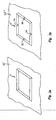
- punching is meant to be here expressed that the contour is not continuous, but has interruptions, so that the diecut is not completely punched out but by connecting webs, which remain due to these interruptions between him and the rest of the bow, with remains connected to the bow. This will be further explained below with reference to Fig. 3b explained in more detail.
- the punching is carried out in that opposite to the punching cylinder, a further cylinder is arranged with a smooth, hard surface, which presses the passing through the gap between the two cylinders arc against the projecting punched metal burrs.
- the sheets After punching the sheets are stacked to dry each other. If the drying process progressed so far that it can no longer lead to blurring of the colors, the stacked stampings are cut out of several sheet comprehensive stacks characterized in that their connecting webs to the respective sheet with a suitable tool by machine or by hand in a separate Operation be severed.
- a punching arrangement of the reproduced in the preamble of claim 1 is known type, in which the punched pieces are punched completely free of the individual sheets and in the directly behind the punching a fixed during operation, is provided with negative pressure suction funnel, which serves to wegzu busyn freed punching.
- negative pressure suction funnel which serves to wegzu busyn freed punching.
- pressure rollers or rollers are provided which press the sheet against a counter-pressure surface until he has left the scope of the suction funnel.
- the invention has for its object to provide a punching arrangement referred to in the preamble of claim 1 way, which can be arranged immediately behind the last printing unit of the offset sheet printing machine without the risk of blurring the last printed ink.
- the punching tool is formed so that no connecting webs remain between the punched pieces and the rest of the sheet, ie the Diecuts are completely punched free.
- a fixed during operation suction device is provided which generates a negative pressure immediately above the surface of the respective sheet, through which the liberated punched product is sucked.
- a stationary during operation fan means which presses with the aid of a gas flow, the sheet to its contact surface despite the negative pressure generated by the suction and stabilized
- fixed during operation is intended to express that the device in question does not move during operation, in particular does not participate in the movements necessary for the further transport and punching of the printed sheets.
- fixed positions of both the suction and blower means during operation can be varied to accommodate the generally different product to product positions of the diecuts to be produced.
- blower device as a suction device, which draws the sheet against the contact surface by means of a negative pressure generated on the side of the contact surface opposite the sheet and provided by holes provided in the contact surface.
- the blower device operates at overpressure and comprises at least one fixed during operation nozzle, which is arranged on the same side of the sheet as the suction and in the immediate vicinity of the punching area a gas stream, preferably a compressed air flow directed against the sheet, by which he counter the effect of the negative pressure of the suction device is pressed against the contact surface and stabilized there.
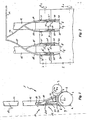
- a punching arrangement 1 comprises two cylinders 2, 3 rotating in the direction of the arrows R1, R2, each having a steel peripheral surface, of which the larger cylinder 2 carries on its otherwise completely smooth lateral surface two punching plates 4, 4 arranged diametrically opposite one another.
- the in Fig. 1 By the gap formed between the cylinders 2, 3, the in Fig. 1 not to scale, but for the sake of clarity greatly enlarged, run in an offset printing machine freshly printed sheet 6 through, which are held and guided in the usual manner in these machines only at its front edge of a corresponding gripping device (not shown).
- the sheet 6 lie with its dry bottom on the outer surface of the larger cylinder 2 and located on this lateral surface punching plates 4, 4 at. Due to the smooth lateral surface of the smaller cylinder 3, the sheets are so against the radially projecting punching plates 4, 4 (see Fig. 3a ) pressed that surrounded by its sharp edge portion of the sheet 6 is punched as a punched out of the sheet completely. It is assumed that at each revolution of the large cylinder 2 two printed sheets 6 pass through the punching assembly 1, so that a punched sheet is punched through the punching plates 4, 4 on two successive sheets 6 at the same point.
- the position of the sheet 6 relative to the punching plates 4, 4 is in Fig. 1 shown so that the blank is completely within the surface of the sheet 6, so that by the punching process, a window is formed, which is surrounded on all sides of sheet material.
- the punching arrangement according to the invention is not limited thereto.
- the punching plates 4, 4, of which also several can be provided for each sheet to be processed 6, can also be arranged so that at least one of them punched a punched product at the edge of the relevant sheet 6.
- suction 8 enters a suction device 11, from which it is sucked off after the complete free dancing.
- the suction port 9 is actually located at a much smaller distance directly above the lateral surface of the cylinder 2, as this Fig. 1 shows.
- the distance between the underside of the funnel 8 adapted to the curvature of the cylinder 2 and the lateral surface of the cylinder 2 is between 0.5 cm and 1.5 cm and is preferably about 1 cm.
- the outlet opening located at the tapered end 10 of the suction funnel 8 opens directly into a Suction line 12, which is connected at its end, not shown, with a vacuum generating blower device and a collecting device for receiving the extracted punched pieces.
- a slide 13 is provided, with the aid of which the strength of the negative pressure can be regulated, through which the punched pieces are sucked.
- this slider is as in Fig. 1 shown directed so obliquely to the longitudinal axis of the suction line 12 that its upper, the width of the passage influencing edge of the suction hopper 8 is farther away. This prevents sucked punched pieces accumulate on the slide 13 and the suction line 12 can clog.
- the size of the suction port 9 of the suction hopper 8 is adjustable in order to optimally adapt to different punching unit sizes ..
- the punch assembly 1 further comprises a fixed during operation fan device 14, from which in the Fig. 2 only one supply line 16 is shown for compressed air, which opens into two manifolds 17, 17 ', each of which in turn splits into two branch lines 18, 19 and 18', 19 'for each suction funnel 8, 8', each via a Distributor 20 into three flexible nozzle lines 21, 22, 23 and 24, 25, 26 and 21 ', 22', 23 'and 24', 25 ', 26' opens.
- Each of the nozzle lines 21 to 26 ' carries at its free end a nozzle 30 which is located at a small distance above the lateral surface of the cylinder 2.
- the distance of the nozzles 30 from the lateral surface of the cylinder 2 is preferably in the range of 2 cm to 4 cm.
- the compressed air emerging from the nozzles 30 which are stationary during operation and which can be regulated in their strength by means of a pressure regulator (not shown) provided in the supply line 16 presses the sheet 6 passing under the nozzles 30 against the jacket surface of the cylinder 2, so that the sheet 6 despite the negative pressure generated by the respective hopper 8 and 8 'in the area in which the liberated punching moves due to the forward movement of the sheet 6, remains stable and can be easily forwarded. It is essential that the freshly printed on his top and therefore still wet sheet 6 remains non-contact on this page and thus blurring of the colors is avoided.
- a manually operable valve 31, 32 and 31 ', 32' is provided, with the help of the compressed air supply to the nozzle 30 in question can be turned off ,
- nozzles 30 Commercially available cooling nozzles for drill stands can be used whose opening has a diameter of about 5 mm. It has been shown that an admission of the nozzle 30 with an overpressure of 4 bar is advantageous.
- the nozzles 30 are in the immediate vicinity of the outer surfaces of the suction funnel 8 and 8 ', whose inlet openings 9 and 9' are only slightly larger than the respective blank to be sucked. This ensures that the sheet 6 are pressed by the emerging from the nozzle 30 compressed air in the immediate vicinity of the area to the lateral surface of the cylinder 2, in which the associated suction hopper 8 generates a negative pressure that could otherwise cause the sheet 6 of the lateral surface of the cylinder 2 stand out. Due to the flexibility of the nozzle lines 21 to 25 ', the nozzles 30 can be pivoted within wide ranges and thus their configuration can be adapted to the contour of the suction opening 9 or 9' to the associated suction funnel 8 or 8 '.
- Fig. 2 how to especially the Fig. 2 also removes several punched pieces can be punched out of the sheet 6 at the same time, then preferably for each punched a separate suction funnel 8, 8 'with the associated nozzle lines 21 to 26 and 21 to 26' is provided.
- a cutout 35 or 35 'of the lateral surface of a cylinder 2 is reproduced, with the actually curved lateral surface cutout 35 or 35' being shown for the sake of clarity.
- Each of the two lateral surface cutouts 35 and 35 ' carries a stamped sheet 4 or 4', wherein the former is formed according to the invention, while the latter corresponds to the prior art.
- the two 4, 4 ' are each about 0.8 mm above the lateral surface of the respective cylinder 2 in the radial direction.
- the punching was printed in an offset sheet-fed press sheet 6 according to the prior art carried out so that the punching plates used in the punching 4 'recesses 36, of which Fig. 3b in each side edge one is reproduced. Through these recesses 36, the blank was not completely punched out of the relevant sheet, but it remained at each recess 36, a connecting web between the punching and the rest of the sheet are, which then later had to be severed by hand.
Landscapes
- Engineering & Computer Science (AREA)
- Mechanical Engineering (AREA)
- Life Sciences & Earth Sciences (AREA)
- Forests & Forestry (AREA)
- Perforating, Stamping-Out Or Severing By Means Other Than Cutting (AREA)
- Details Of Cutting Devices (AREA)
- Discharge By Other Means (AREA)
- Massaging Devices (AREA)
- Filters For Electric Vacuum Cleaners (AREA)
- Motor Or Generator Cooling System (AREA)
Applications Claiming Priority (2)
| Application Number | Priority Date | Filing Date | Title |
|---|---|---|---|
| DE20104247U DE20104247U1 (de) | 2001-03-12 | 2001-03-12 | Stanzanordnung |
| DE20104247U | 2001-03-12 |
Publications (4)
| Publication Number | Publication Date |
|---|---|
| EP1240986A2 EP1240986A2 (de) | 2002-09-18 |
| EP1240986A3 EP1240986A3 (de) | 2004-05-19 |
| EP1240986B1 EP1240986B1 (de) | 2006-10-04 |
| EP1240986B2 true EP1240986B2 (de) | 2010-01-27 |
Family
ID=7954164
Family Applications (1)
| Application Number | Title | Priority Date | Filing Date |
|---|---|---|---|
| EP02005516A Expired - Lifetime EP1240986B2 (de) | 2001-03-12 | 2002-03-11 | Stanzanordnung mit Absaug- sowie Gebläseeinrichtung |
Country Status (4)
| Country | Link |
|---|---|
| EP (1) | EP1240986B2 (cs) |
| AT (1) | ATE341428T1 (cs) |
| CZ (1) | CZ297940B6 (cs) |
| DE (2) | DE20104247U1 (cs) |
Families Citing this family (3)
| Publication number | Priority date | Publication date | Assignee | Title |
|---|---|---|---|---|
| DE20104247U1 (de) † | 2001-03-12 | 2001-09-06 | Offsetdruck Nürnberg GmbH & Co. Papierverarbeitungs-KG, 90411 Nürnberg | Stanzanordnung |
| DE10338352A1 (de) | 2003-08-21 | 2005-03-17 | Cgh Consultants | Verfahren zum Inline-Stanzen beim Bogenoffsetdruck und Bogenoffsetdruckmaschine |
| DE102006038937A1 (de) * | 2006-08-18 | 2008-02-21 | Koenig & Bauer Aktiengesellschaft | Bogenoffsetdruckmaschine mit einer Stanzvorrichtung |
Citations (1)
| Publication number | Priority date | Publication date | Assignee | Title |
|---|---|---|---|---|
| DE20104247U1 (de) † | 2001-03-12 | 2001-09-06 | Offsetdruck Nürnberg GmbH & Co. Papierverarbeitungs-KG, 90411 Nürnberg | Stanzanordnung |
Family Cites Families (10)
| Publication number | Priority date | Publication date | Assignee | Title |
|---|---|---|---|---|
| DD95851A1 (cs) * | 1972-01-17 | 1973-02-20 | ||
| DE2235511C3 (de) * | 1972-07-14 | 1975-02-13 | Automatic Druckmaschinenfabrik Dr. W. Hinniger U. Soehne, 1000 Berlin | Einrichtung zum Stanzen von Lochreihen in endlose Papierbahnen an einer Rotationsdruckmaschine |
| US3998116A (en) * | 1975-03-03 | 1976-12-21 | F. L. Smithe Machine Company, Inc. | Apparatus for removing cut panels from sheet material |
| US5140880A (en) * | 1991-05-08 | 1992-08-25 | Littleton Industrial Consultants, Inc. | Push-pull apparatus and method for web cutting and trim strip removal |
| DE4138277C2 (de) * | 1991-11-21 | 1998-10-29 | Kba Planeta Ag | Verfahren und Vorrichtung zum abschmierfreien Stanzen, Rillen und Perforieren |
| DE4308710A1 (de) * | 1992-03-18 | 1993-10-28 | Schule Gmbh F H | Entfernung von Zuschnitt-Abfallstücken aus Stanzmessern |
| DE4229699C2 (de) * | 1992-09-05 | 1995-09-21 | Heidelberger Druckmasch Ag | Vorrichtung zur kontrollierten Beseitigung von Abfall-Stücken von Bedruckstoffen |
| US5660380A (en) * | 1995-08-15 | 1997-08-26 | W. L. Gore & Associates, Inc. | Vacuum fixture and method for dimensioning and manipulating materials |
| FR2774018B1 (fr) * | 1998-01-28 | 2000-04-07 | Offset Feuilles Nord | Procede de decoupe feuille a feuille avec extraction des rognures de decoupe, dispositif d'extraction de rognures de decoupe, et ligne d'impression et de decoupe feuille a feuille |
| DE29818343U1 (de) * | 1998-10-14 | 2000-02-24 | Heidelberger Druckmaschinen Ag, 69115 Heidelberg | Bogendruckmaschine |
-
2001
- 2001-03-12 DE DE20104247U patent/DE20104247U1/de not_active Expired - Lifetime
-
2002
- 2002-03-11 DE DE50208301T patent/DE50208301D1/de not_active Expired - Lifetime
- 2002-03-11 AT AT02005516T patent/ATE341428T1/de active
- 2002-03-11 EP EP02005516A patent/EP1240986B2/de not_active Expired - Lifetime
- 2002-03-12 CZ CZ20020886A patent/CZ297940B6/cs not_active IP Right Cessation
Patent Citations (1)
| Publication number | Priority date | Publication date | Assignee | Title |
|---|---|---|---|---|
| DE20104247U1 (de) † | 2001-03-12 | 2001-09-06 | Offsetdruck Nürnberg GmbH & Co. Papierverarbeitungs-KG, 90411 Nürnberg | Stanzanordnung |
Also Published As
| Publication number | Publication date |
|---|---|
| ATE341428T1 (de) | 2006-10-15 |
| CZ297940B6 (cs) | 2007-05-02 |
| EP1240986A3 (de) | 2004-05-19 |
| CZ2002886A3 (cs) | 2002-10-16 |
| EP1240986A2 (de) | 2002-09-18 |
| DE50208301D1 (de) | 2006-11-16 |
| EP1240986B1 (de) | 2006-10-04 |
| DE20104247U1 (de) | 2001-09-06 |
Similar Documents
| Publication | Publication Date | Title |
|---|---|---|
| EP0695707B1 (de) | Einrichtung zum berührungsfreien Führen bogenförmigen Materials | |
| EP0706881B1 (de) | Bogenführungsmodul für eine Wendeeinrichtung in einer für Schön- und Widerdruck einsetzbaren Rotations-druckmaschine | |
| DE10356413A1 (de) | Vorrichtung zur veredelnden Bearbeitung von bogenförmigen Substraten | |
| DE19733691C2 (de) | Bogen verarbeitende Rotationsdruckmaschine | |
| EP1867449A1 (de) | Abfallgebläse für eine Bogenstanz- und Prägemaschine | |
| CH654252A5 (de) | Vorrichtung zum fuehren eines bogens auf dem druckzylinder einer druckmaschine. | |
| DE102012002110B4 (de) | Vorrichtung zur Stanzbearbeitung von bogenförmigen Substraten | |
| EP0468254B1 (de) | Querschneider für mit Druckbildern versehene Materialbahnen | |
| EP1935820B1 (de) | Bogenbearbeitungsmaschine mit Bogenbremsvorrichtung und Verfahren zum Reinigen einer Bogenbremsvorrichtung | |
| EP0000011B2 (de) | Bogenrotationsdruckmaschine. | |
| EP1240986B2 (de) | Stanzanordnung mit Absaug- sowie Gebläseeinrichtung | |
| EP0924069B1 (de) | Bogenführungseinrichtung in einer Druckmaschine | |
| AT413274B (de) | Bogenleiteinrichtung in einer rotationsdruckmaschine | |
| DE102004029037A1 (de) | Vorrichtung zum Bearbeiten von Substraten | |
| DE19940534A1 (de) | Druckmaschine mit einer Fingerschutzeinrichtung | |
| DE102007018117B4 (de) | Querschneider für eine Papierbahn | |
| DE4342203C3 (de) | Einrichtung zum Einwirken auf Bogen in einer Bogenrotationsdruckmaschine | |
| EP1656259B1 (de) | Verfahren zum inline-stanzen beim bogenoffsetdruck und bogenoffsetdruckmaschine | |
| EP0068340A1 (de) | Falzapparat | |
| EP1718463B1 (de) | Druckmaschine mit falztrichter | |
| DD249224A1 (de) | Transferzylinder in druckmaschinen | |
| DE102006038937A1 (de) | Bogenoffsetdruckmaschine mit einer Stanzvorrichtung | |
| EP1995064B1 (de) | Bogenglätteinrichtung in Druckmaschinen zur Unterstützung der Bogenführung | |
| EP1916107A2 (de) | Vorrichtung und Verfahren zur veredelnden Bearbeitung von bogenförmigen Substraten in einer Bogendruckmaschinen | |
| DE102019127868A1 (de) | Druckmaschine mit einer Blaseinrichtung vor einem Druckspalt |
Legal Events
| Date | Code | Title | Description |
|---|---|---|---|
| PUAI | Public reference made under article 153(3) epc to a published international application that has entered the european phase |
Free format text: ORIGINAL CODE: 0009012 |
|
| AK | Designated contracting states |
Kind code of ref document: A2 Designated state(s): AT BE CH CY DE DK ES FI FR GB GR IE IT LI LU MC NL PT SE TR |
|
| AX | Request for extension of the european patent |
Free format text: AL;LT;LV;MK;RO;SI |
|
| PUAL | Search report despatched |
Free format text: ORIGINAL CODE: 0009013 |
|
| AK | Designated contracting states |
Kind code of ref document: A3 Designated state(s): AT BE CH CY DE DK ES FI FR GB GR IE IT LI LU MC NL PT SE TR |
|
| AX | Request for extension of the european patent |
Extension state: AL LT LV MK RO SI |
|
| 17P | Request for examination filed |
Effective date: 20041107 |
|
| AKX | Designation fees paid |
Designated state(s): AT BE CH CY DE DK ES FI FR GB GR IE IT LI LU MC NL PT SE TR |
|
| AXX | Extension fees paid |
Extension state: LT Payment date: 20041107 Extension state: LV Payment date: 20041107 Extension state: SI Payment date: 20041107 Extension state: RO Payment date: 20041107 |
|
| 17Q | First examination report despatched |
Effective date: 20050622 |
|
| GRAP | Despatch of communication of intention to grant a patent |
Free format text: ORIGINAL CODE: EPIDOSNIGR1 |
|
| RAP1 | Party data changed (applicant data changed or rights of an application transferred) |
Owner name: OFFSETDRUCK NUERNBERG GMBH & CO. PAPIERVERARBEITU |
|
| GRAS | Grant fee paid |
Free format text: ORIGINAL CODE: EPIDOSNIGR3 |
|
| RIN1 | Information on inventor provided before grant (corrected) |
Inventor name: WIMMER, EUGENC/O OFFSETDRUCK NUERNBERG GMBH & CO. Inventor name: MUECK, THOMASC/O OFFSETDRUCK NUERNBERG GMBH & CO. |
|
| GRAA | (expected) grant |
Free format text: ORIGINAL CODE: 0009210 |
|
| AK | Designated contracting states |
Kind code of ref document: B1 Designated state(s): AT BE CH CY DE DK ES FI FR GB GR IE IT LI LU MC NL PT SE TR |
|
| AX | Request for extension of the european patent |
Extension state: LT LV RO SI |
|
| PG25 | Lapsed in a contracting state [announced via postgrant information from national office to epo] |
Ref country code: IT Free format text: LAPSE BECAUSE OF FAILURE TO SUBMIT A TRANSLATION OF THE DESCRIPTION OR TO PAY THE FEE WITHIN THE PRESCRIBED TIME-LIMIT;WARNING: LAPSES OF ITALIAN PATENTS WITH EFFECTIVE DATE BEFORE 2007 MAY HAVE OCCURRED AT ANY TIME BEFORE 2007. THE CORRECT EFFECTIVE DATE MAY BE DIFFERENT FROM THE ONE RECORDED. Effective date: 20061004 Ref country code: FI Free format text: LAPSE BECAUSE OF FAILURE TO SUBMIT A TRANSLATION OF THE DESCRIPTION OR TO PAY THE FEE WITHIN THE PRESCRIBED TIME-LIMIT Effective date: 20061004 Ref country code: NL Free format text: LAPSE BECAUSE OF FAILURE TO SUBMIT A TRANSLATION OF THE DESCRIPTION OR TO PAY THE FEE WITHIN THE PRESCRIBED TIME-LIMIT Effective date: 20061004 Ref country code: IE Free format text: LAPSE BECAUSE OF FAILURE TO SUBMIT A TRANSLATION OF THE DESCRIPTION OR TO PAY THE FEE WITHIN THE PRESCRIBED TIME-LIMIT Effective date: 20061004 |
|
| REG | Reference to a national code |
Ref country code: GB Ref legal event code: FG4D Free format text: NOT ENGLISH |
|
| REG | Reference to a national code |
Ref country code: CH Ref legal event code: EP |
|
| REG | Reference to a national code |
Ref country code: IE Ref legal event code: FG4D Free format text: LANGUAGE OF EP DOCUMENT: GERMAN |
|
| REF | Corresponds to: |
Ref document number: 50208301 Country of ref document: DE Date of ref document: 20061116 Kind code of ref document: P |
|
| PG25 | Lapsed in a contracting state [announced via postgrant information from national office to epo] |
Ref country code: DK Free format text: LAPSE BECAUSE OF FAILURE TO SUBMIT A TRANSLATION OF THE DESCRIPTION OR TO PAY THE FEE WITHIN THE PRESCRIBED TIME-LIMIT Effective date: 20070104 Ref country code: SE Free format text: LAPSE BECAUSE OF FAILURE TO SUBMIT A TRANSLATION OF THE DESCRIPTION OR TO PAY THE FEE WITHIN THE PRESCRIBED TIME-LIMIT Effective date: 20070104 |
|
| PG25 | Lapsed in a contracting state [announced via postgrant information from national office to epo] |
Ref country code: ES Free format text: LAPSE BECAUSE OF FAILURE TO SUBMIT A TRANSLATION OF THE DESCRIPTION OR TO PAY THE FEE WITHIN THE PRESCRIBED TIME-LIMIT Effective date: 20070115 |
|
| REG | Reference to a national code |
Ref country code: CH Ref legal event code: NV Representative=s name: BOVARD AG PATENTANWAELTE |
|
| GBT | Gb: translation of ep patent filed (gb section 77(6)(a)/1977) |
Effective date: 20070103 |
|
| PG25 | Lapsed in a contracting state [announced via postgrant information from national office to epo] |
Ref country code: PT Free format text: LAPSE BECAUSE OF FAILURE TO SUBMIT A TRANSLATION OF THE DESCRIPTION OR TO PAY THE FEE WITHIN THE PRESCRIBED TIME-LIMIT Effective date: 20070316 |
|
| LTIE | Lt: invalidation of european patent or patent extension |
Effective date: 20061004 |
|
| NLV1 | Nl: lapsed or annulled due to failure to fulfill the requirements of art. 29p and 29m of the patents act | ||
| EN | Fr: translation not filed | ||
| REG | Reference to a national code |
Ref country code: IE Ref legal event code: FD4D |
|
| PLBI | Opposition filed |
Free format text: ORIGINAL CODE: 0009260 |
|
| PLAZ | Examination of admissibility of opposition: despatch of communication + time limit |
Free format text: ORIGINAL CODE: EPIDOSNOPE2 |
|
| PLBA | Examination of admissibility of opposition: reply received |
Free format text: ORIGINAL CODE: EPIDOSNOPE4 |
|
| PLAX | Notice of opposition and request to file observation + time limit sent |
Free format text: ORIGINAL CODE: EPIDOSNOBS2 |
|
| 26 | Opposition filed |
Opponent name: SCHOBER GMBH Effective date: 20070626 |
|
| PLBB | Reply of patent proprietor to notice(s) of opposition received |
Free format text: ORIGINAL CODE: EPIDOSNOBS3 |
|
| BERE | Be: lapsed |
Owner name: OFFSETDRUCK NURNBERG G.M.B.H. & CO. PAPIERVERARBE Effective date: 20070331 |
|
| PG25 | Lapsed in a contracting state [announced via postgrant information from national office to epo] |
Ref country code: BE Free format text: LAPSE BECAUSE OF NON-PAYMENT OF DUE FEES Effective date: 20070331 |
|
| PG25 | Lapsed in a contracting state [announced via postgrant information from national office to epo] |
Ref country code: MC Free format text: LAPSE BECAUSE OF NON-PAYMENT OF DUE FEES Effective date: 20070331 |
|
| PG25 | Lapsed in a contracting state [announced via postgrant information from national office to epo] |
Ref country code: GR Free format text: LAPSE BECAUSE OF FAILURE TO SUBMIT A TRANSLATION OF THE DESCRIPTION OR TO PAY THE FEE WITHIN THE PRESCRIBED TIME-LIMIT Effective date: 20070105 Ref country code: FR Free format text: LAPSE BECAUSE OF FAILURE TO SUBMIT A TRANSLATION OF THE DESCRIPTION OR TO PAY THE FEE WITHIN THE PRESCRIBED TIME-LIMIT Effective date: 20070525 |
|
| PLAB | Opposition data, opponent's data or that of the opponent's representative modified |
Free format text: ORIGINAL CODE: 0009299OPPO |
|
| PG25 | Lapsed in a contracting state [announced via postgrant information from national office to epo] |
Ref country code: FR Free format text: LAPSE BECAUSE OF FAILURE TO SUBMIT A TRANSLATION OF THE DESCRIPTION OR TO PAY THE FEE WITHIN THE PRESCRIBED TIME-LIMIT Effective date: 20061004 |
|
| PLBP | Opposition withdrawn |
Free format text: ORIGINAL CODE: 0009264 |
|
| PLBD | Termination of opposition procedure: decision despatched |
Free format text: ORIGINAL CODE: EPIDOSNOPC1 |
|
| APBM | Appeal reference recorded |
Free format text: ORIGINAL CODE: EPIDOSNREFNO |
|
| APBP | Date of receipt of notice of appeal recorded |
Free format text: ORIGINAL CODE: EPIDOSNNOA2O |
|
| APBQ | Date of receipt of statement of grounds of appeal recorded |
Free format text: ORIGINAL CODE: EPIDOSNNOA3O |
|
| APBW | Interlocutory revision of appeal recorded |
Free format text: ORIGINAL CODE: EPIDOSNIRAPO |
|
| PG25 | Lapsed in a contracting state [announced via postgrant information from national office to epo] |
Ref country code: LU Free format text: LAPSE BECAUSE OF NON-PAYMENT OF DUE FEES Effective date: 20070311 Ref country code: CY Free format text: LAPSE BECAUSE OF FAILURE TO SUBMIT A TRANSLATION OF THE DESCRIPTION OR TO PAY THE FEE WITHIN THE PRESCRIBED TIME-LIMIT Effective date: 20061004 |
|
| PG25 | Lapsed in a contracting state [announced via postgrant information from national office to epo] |
Ref country code: TR Free format text: LAPSE BECAUSE OF FAILURE TO SUBMIT A TRANSLATION OF THE DESCRIPTION OR TO PAY THE FEE WITHIN THE PRESCRIBED TIME-LIMIT Effective date: 20061004 |
|
| PUAH | Patent maintained in amended form |
Free format text: ORIGINAL CODE: 0009272 |
|
| STAA | Information on the status of an ep patent application or granted ep patent |
Free format text: STATUS: PATENT MAINTAINED AS AMENDED |
|
| 27A | Patent maintained in amended form |
Effective date: 20100127 |
|
| AK | Designated contracting states |
Kind code of ref document: B2 Designated state(s): AT BE CH CY DE DK ES FI FR GB GR IE IT LI LU MC NL PT SE TR |
|
| AX | Request for extension of the european patent |
Extension state: LT LV RO SI |
|
| REG | Reference to a national code |
Ref country code: CH Ref legal event code: AEN Free format text: AUFRECHTERHALTUNG DES PATENTES IN GEAENDERTER FORM |
|
| REG | Reference to a national code |
Ref country code: ES Ref legal event code: FD2A Effective date: 20070312 |
|
| REG | Reference to a national code |
Ref country code: CH Ref legal event code: PFA Owner name: OFFSETDRUCK NUERNBERG GMBH & CO. PAPIERVERARBEITU Free format text: OFFSETDRUCK NUERNBERG GMBH & CO. PAPIERVERARBEITUNGS-KG#REICHSWALDSTRASSE 52#90571 SCHWAIG BEI NUERNBERG (DE) -TRANSFER TO- OFFSETDRUCK NUERNBERG GMBH & CO. PAPIERVERARBEITUNGS-KG#REICHSWALDSTRASSE 52#90571 SCHWAIG BEI NUERNBERG (DE) |
|
| PGFP | Annual fee paid to national office [announced via postgrant information from national office to epo] |
Ref country code: CH Payment date: 20120323 Year of fee payment: 11 |
|
| PGFP | Annual fee paid to national office [announced via postgrant information from national office to epo] |
Ref country code: GB Payment date: 20120322 Year of fee payment: 11 |
|
| PGFP | Annual fee paid to national office [announced via postgrant information from national office to epo] |
Ref country code: AT Payment date: 20120321 Year of fee payment: 11 |
|
| REG | Reference to a national code |
Ref country code: CH Ref legal event code: PL |
|
| REG | Reference to a national code |
Ref country code: AT Ref legal event code: MM01 Ref document number: 341428 Country of ref document: AT Kind code of ref document: T Effective date: 20130311 |
|
| GBPC | Gb: european patent ceased through non-payment of renewal fee |
Effective date: 20130311 |
|
| PG25 | Lapsed in a contracting state [announced via postgrant information from national office to epo] |
Ref country code: AT Free format text: LAPSE BECAUSE OF NON-PAYMENT OF DUE FEES Effective date: 20130311 Ref country code: CH Free format text: LAPSE BECAUSE OF NON-PAYMENT OF DUE FEES Effective date: 20130331 Ref country code: LI Free format text: LAPSE BECAUSE OF NON-PAYMENT OF DUE FEES Effective date: 20130331 Ref country code: GB Free format text: LAPSE BECAUSE OF NON-PAYMENT OF DUE FEES Effective date: 20130311 |
|
| REG | Reference to a national code |
Ref country code: DE Ref legal event code: R082 Ref document number: 50208301 Country of ref document: DE Representative=s name: STROHSCHAENK UND KOLLEGEN, DE Ref country code: DE Ref legal event code: R081 Ref document number: 50208301 Country of ref document: DE Owner name: KUEBER, PETER, DE Free format text: FORMER OWNER: ODN DRUCK UND MEDIENSERVICE GMBH & CO. KG, 90571 SCHWAIG, DE Ref country code: DE Ref legal event code: R081 Ref document number: 50208301 Country of ref document: DE Owner name: KUEBER, PETER, DE Free format text: FORMER OWNER: OFFSETDRUCK NUERNBERG GMBH & CO. PAPIERVERARBEITUNGS-KG, 90411 NUERNBERG, DE Ref country code: DE Ref legal event code: R082 Ref document number: 50208301 Country of ref document: DE Representative=s name: PATENTANWAELTE STROHSCHAENK, URI, STRASSER & K, DE |
|
| PGFP | Annual fee paid to national office [announced via postgrant information from national office to epo] |
Ref country code: DE Payment date: 20170529 Year of fee payment: 16 |
|
| REG | Reference to a national code |
Ref country code: DE Ref legal event code: R119 Ref document number: 50208301 Country of ref document: DE |
|
| PG25 | Lapsed in a contracting state [announced via postgrant information from national office to epo] |
Ref country code: DE Free format text: LAPSE BECAUSE OF NON-PAYMENT OF DUE FEES Effective date: 20181002 |