EP1243399A2 - Verfahren und Anlage zur Herstellung einer Folie aus thermoplastischem Kunststoff - Google Patents
Verfahren und Anlage zur Herstellung einer Folie aus thermoplastischem Kunststoff Download PDFInfo
- Publication number
- EP1243399A2 EP1243399A2 EP02003766A EP02003766A EP1243399A2 EP 1243399 A2 EP1243399 A2 EP 1243399A2 EP 02003766 A EP02003766 A EP 02003766A EP 02003766 A EP02003766 A EP 02003766A EP 1243399 A2 EP1243399 A2 EP 1243399A2
- Authority
- EP
- European Patent Office
- Prior art keywords
- film bubble
- calibration device
- plastic
- bubble
- film
- Prior art date
- Legal status (The legal status is an assumption and is not a legal conclusion. Google has not performed a legal analysis and makes no representation as to the accuracy of the status listed.)
- Withdrawn
Links
- 238000000034 method Methods 0.000 title claims abstract description 18
- 229920001169 thermoplastic Polymers 0.000 title claims abstract description 16
- 239000004416 thermosoftening plastic Substances 0.000 title claims abstract description 15
- 238000004519 manufacturing process Methods 0.000 title claims description 9
- 239000004033 plastic Substances 0.000 claims abstract description 38
- 238000007600 charging Methods 0.000 claims description 34
- 239000002184 metal Substances 0.000 claims description 10
- 238000007786 electrostatic charging Methods 0.000 claims description 8
- 238000009434 installation Methods 0.000 claims 1
- 239000011888 foil Substances 0.000 description 20
- 230000005684 electric field Effects 0.000 description 8
- 238000001816 cooling Methods 0.000 description 3
- 238000011161 development Methods 0.000 description 3
- 230000018109 developmental process Effects 0.000 description 3
- 238000007711 solidification Methods 0.000 description 3
- 230000008023 solidification Effects 0.000 description 3
- 230000000694 effects Effects 0.000 description 2
- 239000007921 spray Substances 0.000 description 2
- 230000015572 biosynthetic process Effects 0.000 description 1
- 230000013228 contact guidance Effects 0.000 description 1
- 230000006735 deficit Effects 0.000 description 1
- 238000005516 engineering process Methods 0.000 description 1
- 238000000605 extraction Methods 0.000 description 1
- 239000000155 melt Substances 0.000 description 1
- 239000002985 plastic film Substances 0.000 description 1
- 229920006255 plastic film Polymers 0.000 description 1
- 230000002940 repellent Effects 0.000 description 1
- 239000005871 repellent Substances 0.000 description 1
- 239000012815 thermoplastic material Substances 0.000 description 1
- 230000007704 transition Effects 0.000 description 1
- 230000000007 visual effect Effects 0.000 description 1
Images

Classifications
-
- B—PERFORMING OPERATIONS; TRANSPORTING
- B29—WORKING OF PLASTICS; WORKING OF SUBSTANCES IN A PLASTIC STATE IN GENERAL
- B29C—SHAPING OR JOINING OF PLASTICS; SHAPING OF MATERIAL IN A PLASTIC STATE, NOT OTHERWISE PROVIDED FOR; AFTER-TREATMENT OF THE SHAPED PRODUCTS, e.g. REPAIRING
- B29C71/00—After-treatment of articles without altering their shape; Apparatus therefor
- B29C71/0081—After-treatment of articles without altering their shape; Apparatus therefor using an electric field, e.g. for electrostatic charging
-
- B—PERFORMING OPERATIONS; TRANSPORTING
- B29—WORKING OF PLASTICS; WORKING OF SUBSTANCES IN A PLASTIC STATE IN GENERAL
- B29C—SHAPING OR JOINING OF PLASTICS; SHAPING OF MATERIAL IN A PLASTIC STATE, NOT OTHERWISE PROVIDED FOR; AFTER-TREATMENT OF THE SHAPED PRODUCTS, e.g. REPAIRING
- B29C48/00—Extrusion moulding, i.e. expressing the moulding material through a die or nozzle which imparts the desired form; Apparatus therefor
- B29C48/03—Extrusion moulding, i.e. expressing the moulding material through a die or nozzle which imparts the desired form; Apparatus therefor characterised by the shape of the extruded material at extrusion
- B29C48/09—Articles with cross-sections having partially or fully enclosed cavities, e.g. pipes or channels
- B29C48/10—Articles with cross-sections having partially or fully enclosed cavities, e.g. pipes or channels flexible, e.g. blown foils
-
- B—PERFORMING OPERATIONS; TRANSPORTING
- B29—WORKING OF PLASTICS; WORKING OF SUBSTANCES IN A PLASTIC STATE IN GENERAL
- B29C—SHAPING OR JOINING OF PLASTICS; SHAPING OF MATERIAL IN A PLASTIC STATE, NOT OTHERWISE PROVIDED FOR; AFTER-TREATMENT OF THE SHAPED PRODUCTS, e.g. REPAIRING
- B29C48/00—Extrusion moulding, i.e. expressing the moulding material through a die or nozzle which imparts the desired form; Apparatus therefor
- B29C48/25—Component parts, details or accessories; Auxiliary operations
- B29C48/88—Thermal treatment of the stream of extruded material, e.g. cooling
- B29C48/90—Thermal treatment of the stream of extruded material, e.g. cooling with calibration or sizing, i.e. combined with fixing or setting of the final dimensions of the extruded article
- B29C48/901—Thermal treatment of the stream of extruded material, e.g. cooling with calibration or sizing, i.e. combined with fixing or setting of the final dimensions of the extruded article of hollow bodies
- B29C48/902—Thermal treatment of the stream of extruded material, e.g. cooling with calibration or sizing, i.e. combined with fixing or setting of the final dimensions of the extruded article of hollow bodies internally
-
- B—PERFORMING OPERATIONS; TRANSPORTING
- B29—WORKING OF PLASTICS; WORKING OF SUBSTANCES IN A PLASTIC STATE IN GENERAL
- B29C—SHAPING OR JOINING OF PLASTICS; SHAPING OF MATERIAL IN A PLASTIC STATE, NOT OTHERWISE PROVIDED FOR; AFTER-TREATMENT OF THE SHAPED PRODUCTS, e.g. REPAIRING
- B29C48/00—Extrusion moulding, i.e. expressing the moulding material through a die or nozzle which imparts the desired form; Apparatus therefor
- B29C48/25—Component parts, details or accessories; Auxiliary operations
- B29C48/88—Thermal treatment of the stream of extruded material, e.g. cooling
- B29C48/90—Thermal treatment of the stream of extruded material, e.g. cooling with calibration or sizing, i.e. combined with fixing or setting of the final dimensions of the extruded article
- B29C48/901—Thermal treatment of the stream of extruded material, e.g. cooling with calibration or sizing, i.e. combined with fixing or setting of the final dimensions of the extruded article of hollow bodies
- B29C48/903—Thermal treatment of the stream of extruded material, e.g. cooling with calibration or sizing, i.e. combined with fixing or setting of the final dimensions of the extruded article of hollow bodies externally
-
- B—PERFORMING OPERATIONS; TRANSPORTING
- B29—WORKING OF PLASTICS; WORKING OF SUBSTANCES IN A PLASTIC STATE IN GENERAL
- B29C—SHAPING OR JOINING OF PLASTICS; SHAPING OF MATERIAL IN A PLASTIC STATE, NOT OTHERWISE PROVIDED FOR; AFTER-TREATMENT OF THE SHAPED PRODUCTS, e.g. REPAIRING
- B29C48/00—Extrusion moulding, i.e. expressing the moulding material through a die or nozzle which imparts the desired form; Apparatus therefor
- B29C48/25—Component parts, details or accessories; Auxiliary operations
- B29C48/88—Thermal treatment of the stream of extruded material, e.g. cooling
- B29C48/911—Cooling
- B29C48/9135—Cooling of flat articles, e.g. using specially adapted supporting means
- B29C48/915—Cooling of flat articles, e.g. using specially adapted supporting means with means for improving the adhesion to the supporting means
- B29C48/9165—Electrostatic pinning
-
- B—PERFORMING OPERATIONS; TRANSPORTING
- B29—WORKING OF PLASTICS; WORKING OF SUBSTANCES IN A PLASTIC STATE IN GENERAL
- B29C—SHAPING OR JOINING OF PLASTICS; SHAPING OF MATERIAL IN A PLASTIC STATE, NOT OTHERWISE PROVIDED FOR; AFTER-TREATMENT OF THE SHAPED PRODUCTS, e.g. REPAIRING
- B29C48/00—Extrusion moulding, i.e. expressing the moulding material through a die or nozzle which imparts the desired form; Apparatus therefor
- B29C48/25—Component parts, details or accessories; Auxiliary operations
- B29C48/88—Thermal treatment of the stream of extruded material, e.g. cooling
- B29C48/885—External treatment, e.g. by using air rings for cooling tubular films
-
- B—PERFORMING OPERATIONS; TRANSPORTING
- B29—WORKING OF PLASTICS; WORKING OF SUBSTANCES IN A PLASTIC STATE IN GENERAL
- B29C—SHAPING OR JOINING OF PLASTICS; SHAPING OF MATERIAL IN A PLASTIC STATE, NOT OTHERWISE PROVIDED FOR; AFTER-TREATMENT OF THE SHAPED PRODUCTS, e.g. REPAIRING
- B29C48/00—Extrusion moulding, i.e. expressing the moulding material through a die or nozzle which imparts the desired form; Apparatus therefor
- B29C48/25—Component parts, details or accessories; Auxiliary operations
- B29C48/88—Thermal treatment of the stream of extruded material, e.g. cooling
- B29C48/90—Thermal treatment of the stream of extruded material, e.g. cooling with calibration or sizing, i.e. combined with fixing or setting of the final dimensions of the extruded article
- B29C48/908—Thermal treatment of the stream of extruded material, e.g. cooling with calibration or sizing, i.e. combined with fixing or setting of the final dimensions of the extruded article characterised by calibrator surface, e.g. structure or holes for lubrication, cooling or venting
-
- B—PERFORMING OPERATIONS; TRANSPORTING
- B29—WORKING OF PLASTICS; WORKING OF SUBSTANCES IN A PLASTIC STATE IN GENERAL
- B29C—SHAPING OR JOINING OF PLASTICS; SHAPING OF MATERIAL IN A PLASTIC STATE, NOT OTHERWISE PROVIDED FOR; AFTER-TREATMENT OF THE SHAPED PRODUCTS, e.g. REPAIRING
- B29C48/00—Extrusion moulding, i.e. expressing the moulding material through a die or nozzle which imparts the desired form; Apparatus therefor
- B29C48/25—Component parts, details or accessories; Auxiliary operations
- B29C48/88—Thermal treatment of the stream of extruded material, e.g. cooling
- B29C48/911—Cooling
- B29C48/9115—Cooling of hollow articles
- B29C48/912—Cooling of hollow articles of tubular films
-
- B—PERFORMING OPERATIONS; TRANSPORTING
- B29—WORKING OF PLASTICS; WORKING OF SUBSTANCES IN A PLASTIC STATE IN GENERAL
- B29C—SHAPING OR JOINING OF PLASTICS; SHAPING OF MATERIAL IN A PLASTIC STATE, NOT OTHERWISE PROVIDED FOR; AFTER-TREATMENT OF THE SHAPED PRODUCTS, e.g. REPAIRING
- B29C53/00—Shaping by bending, folding, twisting, straightening or flattening; Apparatus therefor
- B29C53/02—Bending or folding
- B29C53/10—Bending or folding of blown tubular films, e.g. gusseting
Definitions
- the invention relates to a method for producing a film thermoplastic, in which the plastic consists of a Blow head of an extruder emerges with the formation of a film bubble and the Foil bubble subsequently passes through a calibration device in which it opens a predetermined diameter is calibrated and then laid flat by means of a flat laying device and then wound up becomes.
- thermoplastic material This manufacturing process for the production of also as blown film designated films made of thermoplastic material is widely known.
- the plastic in thermoplastic, melted state from the usually annular opening of the Blow head emerges and is immediately inflated to a film bubble, which is below cooling below the solidification temperature solidified.
- the bubble is also replaced by a Calibration device guided and calibrated in its diameter and here then from a flat laying device to a double film web laid flat and then wound up.
- the calibration device is usually in the form of a so-called calibration basket executed, the outside of the film bubble surrounds and includes a plurality of calibration arms, the outside with the circumference of the film bubble in contact to this in their Define and calibrate the diameter.
- the calibration arms can for example, have a plurality of rotatable plastic rollers that Roll on the surface of the bubble and calibrate it at the same time. Embodiments with rotating brushes or the like are also known.
- a contactless calibration of the film bubble can therefore be done be advantageous in certain applications.
- EP 0 273 739 has already proposed that Foil bubble between strong on the inside and outside of the bubble attacking air streams without contact to create contact friction with the resulting surface impairments of the Avoid film bubble.
- the necessary investment in this powerful blowers, air lines and appropriate control technology However, it is very high and there is also the problem that if the air flow is too strong, undesirable temperature influences the bubble can occur, the quality of the film obtained influence negatively.
- the invention has therefore set itself the task of a method for Propose production of a film of thermoplastic, at which is a contactless calibration of the Foil bubble can be done.
- Thermoplastic has the useful property that it can when passing through a sufficiently strong electric field in good allow electrostatic charging in a controllable manner and this Maintain electrostatic charge for a certain period of time.
- Thermoplastic has the useful property that it can when passing through a sufficiently strong electric field in good allow electrostatic charging in a controllable manner and this Maintain electrostatic charge for a certain period of time.
- This Maintain electrostatic charge for a certain period of time uses the invention.
- thermoplastic plastic forming the film bubble before its Cooling below the solidification temperature and before entering the Calibration device is charged electrostatically, it is possible to use this to be guided through the calibration device without contact, if this is included same potential is charged electrically.
- the resulting Repulsive forces between the electrically charged bubble and the Calibration device are sufficient on the one hand, radial forces on the film bubble to exercise this on the outside to their desired diameter calibrate, but at the same time prevent that the bubble with the parts of the calibration device charged with the same potential comes. In this way, the annoying markings, grooves, Damage etc. on the surface of the bubble when passing through by the calibration device in a surprisingly simple manner reliable avoided.
- the charge of the plastic forming the film bubble before entering the calibration device can be carried out in two different ways.
- the flat laying device with which the film bubble after it has passed is laid flat by the calibration device to form a double film web, with an electric charge of the same potential as the plastic and the Calibration device can be acted on, so that the film bubble is also contactless can pass through the lay-up device and therefore also in this No damage to the surface of the film bubble can.
- the electrostatic charging of the plastic forming the film bubble entry into the calibration device should already be sufficient to include a non-contact guidance of the film bubble within the lay-flat device to ensure.
- Embodiment of the invention proposed that the film bubble after the passage through the calibration device and before reaching the Flat laying device again charged with an electrical charge and is electrostatically charged.
- the bubble can a corresponding one between the calibration device and the flat laying device pass through the electric field so that it reappears in the desired manner is electrostatically charged.
- the electrostatic charging of the plastic can be advantageous in one Gap caused between two electrodes, one of which is inside the film bubble is arranged and the other to form one Passage gap for the film bubble the same outside ring-shaped surrounds. Both electrodes have one for the electrostatic charging of the Plastic sufficient electrical potential difference, so that for the electrostatic charge required electric field across Direction of propagation of the film bubble can be generated.
- the plastic can also be electrostatically charged So-called spray electrodes can be achieved, both in both cases positive as well as negative charging can be considered.
- the invention further comprises a plant for producing a film thermoplastic, which is an extruder with a die for the A plastic bubble emerges on the outside of the plastic Calibration device acting on the film bubble and one of the calibration devices subordinate lay-flat device for the film bubble includes and according to the method according to one of Claims 1 to 6 is operated.
- the system points to achieve the desired contactless guidance the film bubble in the calibration device a charging device for the plastic, which is arranged in front of the calibration device and from there are two parts, between which there is a passage gap for the plastic is trained.
- the system according to the invention comprises a High voltage source with mains connection, voltage regulator and rectifier for the generation of pulsed direct current, one pole of which High voltage source to an isolated part of the charging device and the calibration device is connected.
- the Charging device can then, for example, by connecting the further part of the charging device to ground the desired electric field are generated, which is the one forming the film bubble Plastic as it passes through the charging device in the desired electrostatic charges.
- the calibration device is on connected to the same pole of the high voltage source and thus points the same potential as the electrostatically charged bubble, so that the desired repulsion between the bubble and the Calibration device is achieved and the film bubble the contactless Passes through the calibration device and at the same time in its diameter calibrated as desired.
- the charging device explained above can be located between the blow head and calibration device arranged in the running direction of the film bubble are or may be arranged within the die.
- the calibration device advantageously comprises a plurality of bow-like curved metal segments that run along a the perimeter of the foil bubble surrounding circular line are arranged and with the direct current of the High voltage source can be acted on, so that the desired forces without contact from the calibration device over the entire scope of the Foil bubble in the passage area through the calibration device onto the latter can be transmitted without contact friction between the Foil bubble and the calibration device is created.
- Plant can both the electrically insulated part of the Charging device, the calibration head and the flat laying device be connected to the same pole of the high voltage source, so that also in the area of the flat laying device due to the electrostatic Charging the film bubble and loading the flat laying device with the same electrical potential Foil bubble is guaranteed.
- the plant shown in Figure 1 for the production of a film Thermoplastic does not include any of the details shown blow head 1, the extruder with a not visible here melted thermoplastic is applied.
- Out the blow head 1 occurs in a manner known per se via an upper side annular outlet opening of the plastic in thermoplastic state and is immediately inflated into a film bubble 4 and in Direction of arrow L discharged vertically.
- This bubble has one circular cross section with a central axis M.
- thermoplastic state Immediately after exiting the blow head is the film bubble 4 forming plastic due to its high temperature still in thermoplastic state, but cools rapidly below it Solidification temperature, whereby the film bubble 4 into a rigid Condition is transferred.
- the transition between the thermoplastic state and the solidified state of the film bubble 4 is characterized by a so-called Frost line F marked, which is indicated in Figure 1.
- the charging device 5 consists of two parts, namely one Inner ring 51, which is arranged in the interior of the film bubble 4, and an outer ring 50 which around the inner ring 51 while leaving a annular passage gap 52 is arranged through which the Foil bubble 4 passes through.
- the outer ring 50 is not connected to one via a connecting line 53 High voltage source shown with mains connection, voltage regulator and Rectifier for the generation of pulsed direct current at one pole the same, so that the outer ring with that of the High voltage source emitted pulsed direct current can be applied is.
- the outer ring 50 is not closer to the other system parts in FIG shown in an electrically insulated manner.
- the inner ring 51 is grounded, for example, so that between the outer and inner ring 50, 51 a transverse, in particular perpendicular to Running direction L of the film bubble 4 generated electric field E. which is the one passing through the passage gap 52 Foil bubble 4 penetrates transversely to its running direction L.
- Foil bubble 4 As a result of the prevailing between outer ring 50 and inner ring 51 Potential difference and the generated electric field E is the Foil bubble 4 forming plastic when passing through the Charging device electrostatically charged in the desired manner.
- both positive and negative charging of the Foil bubble can be achieved and the amount of this charge can also by appropriate control and regulation of the charging device 5 connected via the connecting line 53 high voltage source can be set individually.
- the electrostatically charged in this way Foil bubble 4 follows the charging device 5 and above its frost line F, d. h in the solidified state in a calibration device 2 a, in which the film bubble 4 is calibrated in its scope.
- the calibration device 2 includes a film bubble 4 circumferential calibration basket 20, on the inside in Direction towards that passing through the calibration device 2 Foil bubble 4 a plurality of support arms 21 are arranged.
- This Support arms 21 carry on their free, the outer circumference of the film bubble 4 adjacent end each metal segments 22, their number and arrangement are shown only schematically in FIG.
- the calibration device 2 is also connected to the via a connecting line 23 High voltage source connected, as is also the case with the charging device 5 via the connecting line 53 is the case.
- the calibration device has the same electrical potential as on the Charging device and on the film bubble 4 charged by this on.
- This electrical potential acts via the metal segments 22, which in close proximity to the surface of the same potential electrostatic charged bubble 4 are positioned on the bubble 4, causing repulsive forces between the calibration device and Set foil bubble 4.
- the film bubble 4 electrostatically charged in the same way acting force directed radially in the direction of the central axis M. to calibrate the film bubble 4 as well as resulting from the repulsive Forces between the metal segments 22 and the surface of the Foil bubble 4 setting distance can be determined individually.
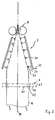
- FIG. 2 shows a further development of the system according to the invention optionally in addition to the training according to FIG. 1 can and connects above the calibration device 2.
- the film bubble 4 which can be seen in the lower area of FIG has already passed the calibration device 2 according to FIG. 1 and is in Running direction according to arrows L further in the vertical direction along the Central axis M moves. After sufficient cooling of the calibrated Foil bubble 4 is this by means of a flat laying device 3, which in the figure 2 is only shown schematically, laid flat to form a double film web and pulled through a pair of draw rollers 8, whereupon they one Extraction and take-up device, not shown, is supplied.
- the Foil bubble 4 in the flat laying device 3 without contact.
- the flat laying device 3 comprises a support frame 30 a large number of which faces the surface of the film bubble 4 of support arms 31 are arranged on their free, the film bubble 4th adjacent ends each have metal segments 32.
- a Connection line 33 is the flat laying device 3 in turn to a electrical high voltage source connectable with and from this generated pulsed direct current.
- the metal segments 32 of the flat laying device 3 the same electrical potential is applied, which is also electrically by the Charging device 5 corresponds to charged bubble 4.
- the film bubble 4 is again passed through the passage gap 62 and the electrically insulated Outer ring 60 is connected to the electrical via a connecting line 63 Voltage of the high voltage source can be applied with the same potential, so that the film bubble 4 in passing through the charging device 6 in analogous to that of the charging device 5 again electrostatically can be charged to the contactless lay flat in the To ensure flat laying device 3.
- the flat laying device 3 is only schematic and strong shown in simplified form, with particular reference to the representation of Entry guides and side guides for the film bladder 4 are omitted has been. However, these can be electrostatic in the same way be charged to act on the film bubble 4 without contact.
- charging devices 5 and / or 6 with inner rings and Outer rings can also use so-called spray electrodes, which are suitable for the electrostatic charging of plastic films.
Landscapes
- Engineering & Computer Science (AREA)
- Mechanical Engineering (AREA)
- Physics & Mathematics (AREA)
- Thermal Sciences (AREA)
- Extrusion Moulding Of Plastics Or The Like (AREA)
- Shaping By String And By Release Of Stress In Plastics And The Like (AREA)
Abstract
Description
- Figur 1
- in schematisierter Darstellung eine Anlage zur Herstellung einer Folie im Bereich ihres Blaskopfes und der Kalibriereinrichtung,
- Figur 2
- eine weitere Ausführungsform einer Anlage zur Herstellung einer Folie im Bereich der Flachlegeeinrichtung.
Claims (12)
- Verfahren zur Herstellung einer Folie aus thermoplastischem Kunststoff, bei welchem der Kunststoff aus einem Blaskopf eines Extruders unter Ausbildung einer Folienblase austritt und die Folienblase nachfolgend eine Kalibriereinrichtung durchläuft, in der sie auf einen vorbestimmbaren Durchmesser kalibriert wird sowie anschließend mittels einer Flachlegeeinrichtung flachgelegt wird, dadurch gekennzeichnet, daß der die Folienblase bildende Kunststoff vor dem Eintritt in die Kalibriereinrichtung mit einer elektrischen Ladung beaufschlagt und elektrostatisch aufgeladen wird und die Kalibriereinrichtung mit einer elektrischen Ladung gleichen Potentials in der Weise aufgeladen wird, daß die Folienblase berührungslos die Kalibriereinrichtung durchläuft.
- Verfahren nach Anspruch 1, dadurch gekennzeichnet, daß der Kunststoff nach seinem Austritt aus dem Blaskopf elektrostatisch aufgeladen wird.
- Verfahren nach Anspruch 1, dadurch gekennzeichnet, daß der Kunststoff vor seinem Austritt aus dem Blaskopf innerhalb desselben elektrostatisch aufgeladen wird.
- Verfahren nach einem der Ansprüche 1 bis 3, dadurch gekennzeichnet, daß die Flachlegeeinrichtung mit einer elektrischen Ladung gleichen Potentials wie der Kunststoff und die Kalibriereinrichtung aufgeladen wird, dergestalt, daß die Folienblase berührungslos die Flachlegeeinrichtung durchläuft.
- Verfahren nach Anspruch 4, dadurch gekennzeichnet, daß der die Folienblase bildende Kunststoff nach dem Durchlauf durch die Kalibriereinrichtung und vor dem Erreichen der Flachlegeeinrichtung erneut mit elektrischer Ladung beaufschlagt und elektrostatisch aufgeladen wird.
- Verfahren nach einem der Ansprüche 1 bis 5, dadurch gekennzeichnet, daß der die Folienblase bildende Kunststoff einen zwischen zwei Elektroden ausgebildeten Spalt durchläuft, wobei die Elektroden eine für die elektrostatische Aufladung des Kunststoffes ausreichende elektrische Potentialdifferenz aufweisen.
- Anlage zur Herstellung einer Folie aus thermoplastischem Kunststoff, die einen Extruder mit Blaskopf für den Austritt einer Folienblase aus dem Kunststoff, eine außenseitig auf die Folienblase einwirkende Kalibriereinrichtung sowie eine der Kalibriereinrichtung nachgeordnete Flachlegeeinrichtung für die Folienblase umfaßt und nach dem Verfahren gemäß einem der Ansprüche 1 bis 6 betrieben wird, gekennzeichnet durch eine vor der Kalibriereinrichtung angeordnete Aufladungseinrichtung für den Kunststoff mit zwei Teilen, zwischen denen ein Durchtrittsspalt für den Kunststoff ausgebildet ist sowie eine Hochspannungsquelle mit Netzanschluß, Spannungsregler und Gleichrichter für die Erzeugung von gepulstem Gleichstrom, deren einer Pol an ein isoliert gelagertes Teil der Aufladungseinrichtung und die Kalibriereinrichtung angeschlossen ist.
- Anlage nach Anspruch 7, dadurch gekennzeichnet, daß die Aufladungseinrichtung zwischen Blaskopf und Kalibriereinrichtung in Laufrichtung der Folienblase gesehen angeordnet ist.
- Anlage nach Anspruch 7, dadurch gekennzeichnet, daß die Aufladungseinrichtung innerhalb des Blaskopfes angeordnet ist.
- Anlage nach einem der Ansprüche 7 bis 9, dadurch gekennzeichnet, daß die Kalibriereinrichtung eine Vielzahl von bügelartig gebogenen Metallsegmenten umfaßt, die entlang einer den Umfang der Folienblase umgebenden Kreislinie angeordnet sind und mit dem Gleichstrom der Hochspannungsquelle beaufschlagbar sind.
- Anlage nach einem der Ansprüche 7 bis 10, dadurch gekennzeichnet, daß das elektrisch isoliert gelagerte Teil der Aufladungseinrichtung, der Kalibrierkorb und die Flachlegeeinrichtung mit dem gleichen Pol der Hochspannungsquelle verbunden sind.
- Anlage nach Anspruch 11, dadurch gekennzeichnet, daß zwischen Kalibriereinrichtung und Flachlegeeinrichtung in Laufrichtung der Folienblase gesehen eine weitere Aufladungseinrichtung für die Folienblase vorgesehen ist.
Applications Claiming Priority (2)
| Application Number | Priority Date | Filing Date | Title |
|---|---|---|---|
| DE10113089A DE10113089C1 (de) | 2001-03-17 | 2001-03-17 | Verfahren und Anlage zur Herstellung einer Folie aus thermoplastischem Kunststoff |
| DE10113089 | 2001-03-17 |
Publications (2)
| Publication Number | Publication Date |
|---|---|
| EP1243399A2 true EP1243399A2 (de) | 2002-09-25 |
| EP1243399A3 EP1243399A3 (de) | 2003-12-03 |
Family
ID=7677965
Family Applications (1)
| Application Number | Title | Priority Date | Filing Date |
|---|---|---|---|
| EP02003766A Withdrawn EP1243399A3 (de) | 2001-03-17 | 2002-02-20 | Verfahren und Anlage zur Herstellung einer Folie aus thermoplastischem Kunststoff |
Country Status (4)
| Country | Link |
|---|---|
| US (1) | US20020180111A1 (de) |
| EP (1) | EP1243399A3 (de) |
| JP (1) | JP2002326269A (de) |
| DE (1) | DE10113089C1 (de) |
Cited By (2)
| Publication number | Priority date | Publication date | Assignee | Title |
|---|---|---|---|---|
| EP1537973A3 (de) * | 2003-11-21 | 2009-11-18 | Kiefel Extrusion Gmbh | Kalibrierkorb |
| CN114770914A (zh) * | 2022-03-24 | 2022-07-22 | 广州市普同实验分析仪器有限公司 | 膜泡定型装置 |
Families Citing this family (6)
| Publication number | Priority date | Publication date | Assignee | Title |
|---|---|---|---|---|
| CA2691559A1 (en) * | 2007-06-28 | 2008-12-31 | Reifenhaeuser Gmbh & Co. Kg Maschinenfabrik | Device for producing blown films |
| EP2298678B1 (de) * | 2009-09-18 | 2012-02-22 | Reifenhäuser GmbH & Co. Maschinenfabrik | Wickelvorrichtung |
| EP3216583B1 (de) | 2016-03-11 | 2021-04-28 | Reifenhäuser GmbH & Co. KG Maschinenfabrik | Koextrusionsadapter |
| CN110181800B (zh) * | 2019-06-28 | 2021-05-28 | 重庆瑞霆塑胶有限公司 | 倾斜架调整机构 |
| CN111497203B (zh) * | 2020-04-30 | 2021-10-15 | 福建连众智惠实业有限公司 | 一种人字夹板自动开合调整机构 |
| CN113829598A (zh) * | 2021-09-29 | 2021-12-24 | 墨现科技(东莞)有限公司 | 压阻薄膜及其制备方法和应用 |
Family Cites Families (7)
| Publication number | Priority date | Publication date | Assignee | Title |
|---|---|---|---|---|
| US3436442A (en) * | 1965-10-12 | 1969-04-01 | Walter R Saks | Process and apparatus for manufacturing flocked fabric |
| US3750948A (en) * | 1971-11-09 | 1973-08-07 | Nikka Kk | Apparatus for depositing powdered substance on the inner surface of inflation tube |
| FR2415528A1 (fr) * | 1978-01-25 | 1979-08-24 | Cellophane Sa | Amelioration aux procedes de fabrication de films par placage electrostatique |
| JPS564434A (en) * | 1979-06-23 | 1981-01-17 | Koichi Hirata | Manufacturing method of reinforced film tube |
| DE3014989C2 (de) * | 1980-04-18 | 1991-01-24 | Windmöller & Hölscher, 4540 Lengerich | Verfahren zur Steuerung der Foliendicke an einer Blasfolienextruderanlage |
| US4728277A (en) * | 1986-12-30 | 1988-03-01 | Mirek Planeta | Film-handling devices for thin flexible films |
| DE19719048A1 (de) * | 1997-05-06 | 1998-11-12 | Reifenhaeuser Masch | Verfahren und Anlage zum Aufwickeln einer Kunststoff-Folie zu einem Coil im Zuge der Herstellung von Blasfolien |
-
2001
- 2001-03-17 DE DE10113089A patent/DE10113089C1/de not_active Expired - Fee Related
-
2002
- 2002-02-20 EP EP02003766A patent/EP1243399A3/de not_active Withdrawn
- 2002-03-13 JP JP2002069102A patent/JP2002326269A/ja not_active Ceased
- 2002-03-18 US US10/101,547 patent/US20020180111A1/en not_active Abandoned
Cited By (2)
| Publication number | Priority date | Publication date | Assignee | Title |
|---|---|---|---|---|
| EP1537973A3 (de) * | 2003-11-21 | 2009-11-18 | Kiefel Extrusion Gmbh | Kalibrierkorb |
| CN114770914A (zh) * | 2022-03-24 | 2022-07-22 | 广州市普同实验分析仪器有限公司 | 膜泡定型装置 |
Also Published As
| Publication number | Publication date |
|---|---|
| EP1243399A3 (de) | 2003-12-03 |
| JP2002326269A (ja) | 2002-11-12 |
| DE10113089C1 (de) | 2002-08-14 |
| US20020180111A1 (en) | 2002-12-05 |
Similar Documents
| Publication | Publication Date | Title |
|---|---|---|
| EP0115804B1 (de) | Verfahren zum Herstellen einer Weichkunststoffolie | |
| DE3628201A1 (de) | Verfahren und vorrichtung zur ausbildung einer schlauchfolie | |
| DE2951449A1 (de) | Verfahren und vorrichtung zum herstellen von zweischichtigem bahnmaterial | |
| EP2347878B1 (de) | Verfahren zur herstellung von peroxidvernetzten polyethylenrohren in einer extrusionslinie | |
| DE102013012134A1 (de) | Vorrichtung zur Herstellung von inline gereckten Folien | |
| EP1488910B1 (de) | Vorrichtung zur Herstellung einer Folie aus thermoplastischem Kunststoff | |
| DE102011018320A1 (de) | Verfahren zur Dickenregelung von Blasfolien | |
| DE102015006891A1 (de) | Anlage zum Herstellen einer Folienbahn sowie Verfahren zum Betreiben einer solchen Anlage | |
| DE10113089C1 (de) | Verfahren und Anlage zur Herstellung einer Folie aus thermoplastischem Kunststoff | |
| DE102015016825A1 (de) | Kühlring für eine Blasfolienanlage, Blasfolienanlage und Verfahren zum Betreiben einer Blasfolienanlage | |
| EP1851027B1 (de) | Vorrichtung und Verfahren zum Antrieb einer Vorheizwalzenanordnung in einer Kalander-Vorrichtung | |
| DE102008006818A1 (de) | Vorrichtung zur Herstellung von Blasfolie | |
| DE102011109385A1 (de) | Variables Längsreckwerk für das Verstrecken einer Kunststofffolie | |
| WO2009000510A2 (de) | Vorrichtung zur herstellung von blasfolien | |
| EP0553367B1 (de) | Vorrichtung zum Herstellen von Schlauchfolien | |
| EP0850747B1 (de) | Vorrichtung zum Anlegen einer aus einer Breitschlitzdüse austretenden Folie an eine sich drehende Abzugswalze | |
| EP0920973B1 (de) | Vorrichtung zum Anlegen einer aus einer Breitschlitzdüse austretenden Folie an eine sich drehende Abzugswalze | |
| DE2162229A1 (de) | Verfahren und vorrichtung zur einspeisung von ausgangsstoffen in den scherspalt von maschinen zur herstellung von flaechigen kunststoffgebilden | |
| DE102019126219B3 (de) | Verfahren zum Betreiben einer Anlage zum Herstellen einer Folienbahn und Anlage zur Durchführung dieses Verfahrens | |
| DE3640365C2 (de) | ||
| DE19842778B4 (de) | Verfahren und Werkzeuganordnung zur Herstellung einer Schlauchfolie | |
| EP4384371B1 (de) | Streckvorrichtung und verfahren zum verstrecken einer kunststofffolie in ihrer transportrichtung | |
| DE19631640C1 (de) | Verfahren zur Regelung der Foliendicke an einer Blasfolienanlage | |
| DE102018103853A1 (de) | Verfahren zur Ausbildung einer Harzfolie | |
| DE102004017952B4 (de) | Vorrichtung zum Transport eines Folienschlauches |
Legal Events
| Date | Code | Title | Description |
|---|---|---|---|
| PUAI | Public reference made under article 153(3) epc to a published international application that has entered the european phase |
Free format text: ORIGINAL CODE: 0009012 |
|
| AK | Designated contracting states |
Kind code of ref document: A2 Designated state(s): AT BE CH CY DE DK ES FI FR GB GR IE IT LI LU MC NL PT SE TR |
|
| AX | Request for extension of the european patent |
Free format text: AL;LT;LV;MK;RO;SI |
|
| PUAL | Search report despatched |
Free format text: ORIGINAL CODE: 0009013 |
|
| AK | Designated contracting states |
Kind code of ref document: A3 Designated state(s): AT BE CH CY DE DK ES FI FR GB GR IE IT LI LU MC NL PT SE TR |
|
| AX | Request for extension of the european patent |
Extension state: AL LT LV MK RO SI |
|
| AKX | Designation fees paid | ||
| REG | Reference to a national code |
Ref country code: DE Ref legal event code: 8566 |
|
| STAA | Information on the status of an ep patent application or granted ep patent |
Free format text: STATUS: THE APPLICATION IS DEEMED TO BE WITHDRAWN |
|
| 18D | Application deemed to be withdrawn |
Effective date: 20040604 |