EP1243400A2 - Vorrichtung zum Herstellen von Wellrohren - Google Patents
Vorrichtung zum Herstellen von Wellrohren Download PDFInfo
- Publication number
- EP1243400A2 EP1243400A2 EP01129884A EP01129884A EP1243400A2 EP 1243400 A2 EP1243400 A2 EP 1243400A2 EP 01129884 A EP01129884 A EP 01129884A EP 01129884 A EP01129884 A EP 01129884A EP 1243400 A2 EP1243400 A2 EP 1243400A2
- Authority
- EP
- European Patent Office
- Prior art keywords
- mold
- mold jaws
- machine table
- jaws
- molding section
- Prior art date
- Legal status (The legal status is an assumption and is not a legal conclusion. Google has not performed a legal analysis and makes no representation as to the accuracy of the status listed.)
- Granted
Links
Images

Classifications
-
- B—PERFORMING OPERATIONS; TRANSPORTING
- B29—WORKING OF PLASTICS; WORKING OF SUBSTANCES IN A PLASTIC STATE IN GENERAL
- B29C—SHAPING OR JOINING OF PLASTICS; SHAPING OF MATERIAL IN A PLASTIC STATE, NOT OTHERWISE PROVIDED FOR; AFTER-TREATMENT OF THE SHAPED PRODUCTS, e.g. REPAIRING
- B29C49/00—Blow-moulding, i.e. blowing a preform or parison to a desired shape within a mould; Apparatus therefor
- B29C49/0015—Making articles of indefinite length, e.g. corrugated tubes
- B29C49/0021—Making articles of indefinite length, e.g. corrugated tubes using moulds or mould parts movable in a closed path, e.g. mounted on movable endless supports
- B29C49/0022—Making articles of indefinite length, e.g. corrugated tubes using moulds or mould parts movable in a closed path, e.g. mounted on movable endless supports characterised by mould return means
-
- B—PERFORMING OPERATIONS; TRANSPORTING
- B29—WORKING OF PLASTICS; WORKING OF SUBSTANCES IN A PLASTIC STATE IN GENERAL
- B29C—SHAPING OR JOINING OF PLASTICS; SHAPING OF MATERIAL IN A PLASTIC STATE, NOT OTHERWISE PROVIDED FOR; AFTER-TREATMENT OF THE SHAPED PRODUCTS, e.g. REPAIRING
- B29C48/00—Extrusion moulding, i.e. expressing the moulding material through a die or nozzle which imparts the desired form; Apparatus therefor
- B29C48/03—Extrusion moulding, i.e. expressing the moulding material through a die or nozzle which imparts the desired form; Apparatus therefor characterised by the shape of the extruded material at extrusion
- B29C48/09—Articles with cross-sections having partially or fully enclosed cavities, e.g. pipes or channels
-
- B—PERFORMING OPERATIONS; TRANSPORTING
- B29—WORKING OF PLASTICS; WORKING OF SUBSTANCES IN A PLASTIC STATE IN GENERAL
- B29C—SHAPING OR JOINING OF PLASTICS; SHAPING OF MATERIAL IN A PLASTIC STATE, NOT OTHERWISE PROVIDED FOR; AFTER-TREATMENT OF THE SHAPED PRODUCTS, e.g. REPAIRING
- B29C48/00—Extrusion moulding, i.e. expressing the moulding material through a die or nozzle which imparts the desired form; Apparatus therefor
- B29C48/03—Extrusion moulding, i.e. expressing the moulding material through a die or nozzle which imparts the desired form; Apparatus therefor characterised by the shape of the extruded material at extrusion
- B29C48/13—Articles with a cross-section varying in the longitudinal direction, e.g. corrugated pipes
-
- B—PERFORMING OPERATIONS; TRANSPORTING
- B29—WORKING OF PLASTICS; WORKING OF SUBSTANCES IN A PLASTIC STATE IN GENERAL
- B29C—SHAPING OR JOINING OF PLASTICS; SHAPING OF MATERIAL IN A PLASTIC STATE, NOT OTHERWISE PROVIDED FOR; AFTER-TREATMENT OF THE SHAPED PRODUCTS, e.g. REPAIRING
- B29C48/00—Extrusion moulding, i.e. expressing the moulding material through a die or nozzle which imparts the desired form; Apparatus therefor
- B29C48/25—Component parts, details or accessories; Auxiliary operations
- B29C48/30—Extrusion nozzles or dies
- B29C48/303—Extrusion nozzles or dies using dies or die parts movable in a closed circuit, e.g. mounted on movable endless support
-
- B—PERFORMING OPERATIONS; TRANSPORTING
- B29—WORKING OF PLASTICS; WORKING OF SUBSTANCES IN A PLASTIC STATE IN GENERAL
- B29C—SHAPING OR JOINING OF PLASTICS; SHAPING OF MATERIAL IN A PLASTIC STATE, NOT OTHERWISE PROVIDED FOR; AFTER-TREATMENT OF THE SHAPED PRODUCTS, e.g. REPAIRING
- B29C49/00—Blow-moulding, i.e. blowing a preform or parison to a desired shape within a mould; Apparatus therefor
- B29C49/0015—Making articles of indefinite length, e.g. corrugated tubes
- B29C49/0023—Making articles of indefinite length, e.g. corrugated tubes using adjustable machine tables, e.g. to align extrusion nozzles with the moulds
-
- B—PERFORMING OPERATIONS; TRANSPORTING
- B29—WORKING OF PLASTICS; WORKING OF SUBSTANCES IN A PLASTIC STATE IN GENERAL
- B29C—SHAPING OR JOINING OF PLASTICS; SHAPING OF MATERIAL IN A PLASTIC STATE, NOT OTHERWISE PROVIDED FOR; AFTER-TREATMENT OF THE SHAPED PRODUCTS, e.g. REPAIRING
- B29C49/00—Blow-moulding, i.e. blowing a preform or parison to a desired shape within a mould; Apparatus therefor
- B29C49/42—Component parts, details or accessories; Auxiliary operations
- B29C49/48—Moulds
- B29C49/4823—Moulds with incorporated heating or cooling means
- B29C2049/4825—Moulds with incorporated heating or cooling means for cooling moulds or mould parts
-
- B—PERFORMING OPERATIONS; TRANSPORTING
- B29—WORKING OF PLASTICS; WORKING OF SUBSTANCES IN A PLASTIC STATE IN GENERAL
- B29C—SHAPING OR JOINING OF PLASTICS; SHAPING OF MATERIAL IN A PLASTIC STATE, NOT OTHERWISE PROVIDED FOR; AFTER-TREATMENT OF THE SHAPED PRODUCTS, e.g. REPAIRING
- B29C35/00—Heating, cooling or curing, e.g. crosslinking or vulcanising; Apparatus therefor
- B29C35/16—Cooling
-
- B—PERFORMING OPERATIONS; TRANSPORTING
- B29—WORKING OF PLASTICS; WORKING OF SUBSTANCES IN A PLASTIC STATE IN GENERAL
- B29C—SHAPING OR JOINING OF PLASTICS; SHAPING OF MATERIAL IN A PLASTIC STATE, NOT OTHERWISE PROVIDED FOR; AFTER-TREATMENT OF THE SHAPED PRODUCTS, e.g. REPAIRING
- B29C48/00—Extrusion moulding, i.e. expressing the moulding material through a die or nozzle which imparts the desired form; Apparatus therefor
- B29C48/001—Combinations of extrusion moulding with other shaping operations
- B29C48/0018—Combinations of extrusion moulding with other shaping operations combined with shaping by orienting, stretching or shrinking, e.g. film blowing
-
- B—PERFORMING OPERATIONS; TRANSPORTING
- B29—WORKING OF PLASTICS; WORKING OF SUBSTANCES IN A PLASTIC STATE IN GENERAL
- B29C—SHAPING OR JOINING OF PLASTICS; SHAPING OF MATERIAL IN A PLASTIC STATE, NOT OTHERWISE PROVIDED FOR; AFTER-TREATMENT OF THE SHAPED PRODUCTS, e.g. REPAIRING
- B29C49/00—Blow-moulding, i.e. blowing a preform or parison to a desired shape within a mould; Apparatus therefor
- B29C49/0015—Making articles of indefinite length, e.g. corrugated tubes
- B29C49/0025—Making articles of indefinite length, e.g. corrugated tubes subsequent mould cavities being different, e.g. for making bells
-
- B—PERFORMING OPERATIONS; TRANSPORTING
- B29—WORKING OF PLASTICS; WORKING OF SUBSTANCES IN A PLASTIC STATE IN GENERAL
- B29C—SHAPING OR JOINING OF PLASTICS; SHAPING OF MATERIAL IN A PLASTIC STATE, NOT OTHERWISE PROVIDED FOR; AFTER-TREATMENT OF THE SHAPED PRODUCTS, e.g. REPAIRING
- B29C49/00—Blow-moulding, i.e. blowing a preform or parison to a desired shape within a mould; Apparatus therefor
- B29C49/0015—Making articles of indefinite length, e.g. corrugated tubes
- B29C49/0027—Making articles of indefinite length, e.g. corrugated tubes involving the change of moulds, e.g. in production processes without interrupting the production processes
-
- B—PERFORMING OPERATIONS; TRANSPORTING
- B29—WORKING OF PLASTICS; WORKING OF SUBSTANCES IN A PLASTIC STATE IN GENERAL
- B29C—SHAPING OR JOINING OF PLASTICS; SHAPING OF MATERIAL IN A PLASTIC STATE, NOT OTHERWISE PROVIDED FOR; AFTER-TREATMENT OF THE SHAPED PRODUCTS, e.g. REPAIRING
- B29C49/00—Blow-moulding, i.e. blowing a preform or parison to a desired shape within a mould; Apparatus therefor
- B29C49/42—Component parts, details or accessories; Auxiliary operations
- B29C49/42407—Procedures for start-up or material change
- B29C49/42408—Temperature conditioning, e.g. pre-heating of the moulds
-
- B—PERFORMING OPERATIONS; TRANSPORTING
- B29—WORKING OF PLASTICS; WORKING OF SUBSTANCES IN A PLASTIC STATE IN GENERAL
- B29C—SHAPING OR JOINING OF PLASTICS; SHAPING OF MATERIAL IN A PLASTIC STATE, NOT OTHERWISE PROVIDED FOR; AFTER-TREATMENT OF THE SHAPED PRODUCTS, e.g. REPAIRING
- B29C49/00—Blow-moulding, i.e. blowing a preform or parison to a desired shape within a mould; Apparatus therefor
- B29C49/42—Component parts, details or accessories; Auxiliary operations
- B29C49/48—Moulds
- B29C49/4823—Moulds with incorporated heating or cooling means
-
- B—PERFORMING OPERATIONS; TRANSPORTING
- B29—WORKING OF PLASTICS; WORKING OF SUBSTANCES IN A PLASTIC STATE IN GENERAL
- B29L—INDEXING SCHEME ASSOCIATED WITH SUBCLASS B29C, RELATING TO PARTICULAR ARTICLES
- B29L2023/00—Tubular articles
- B29L2023/18—Pleated or corrugated hoses
Definitions
- the present invention relates to a device for producing corrugated pipes made of thermoplastic, in which in a circuit complementary in pairs Shaping jaws together along an adjoining spray head Forming line guided, moved apart at the end of the molding line and separately from each other to their beginning, with a molding line device to move the mold jaws along the molding line and one Return conveyor for returning the mold jaws from the end of the molding section to begin with, the forming section device having a machine table with a lower guide and lower drive means for the mold jaws and a Cover frame fastened to the machine table with an upper guide and upper drive means for the mold jaws.
- the return conveyors can have a gripper arm, which grips a mold jaw located at the end of the molding section, to the beginning the molding line moves, the mold jaw sets there and back to the end the molding line moves to grip the next mold jaw there again.
- the molding line itself is the mold jaws of separate drives, on the one hand lie on the machine table and secondly on the cover frame above are arranged, moved.
- a shuttle type corrugated pipe system is known from EP 0 764 516 A2.
- a gantry crane is anchored to a base plate on which the molding line lies or the mold jaws are moved along the molding path.
- this known system is disadvantageous in several ways. To the for one, the system is not very variable.
- a corrugated pipe system is also known in which the Mold jaw pairs are summarized in two groups.
- a first group is mounted on a sled that can be moved back and forth on a lower support frame is.
- a second group of mold jaws is supported on a slide, which can be moved back and forth on an upper support frame.
- the mold jaws are included Can be moved apart and moved together on the sled. To the mold jaws drive back, they are first moved apart on the sled, then the carriage with the extended mold jaws on the Mold the other slide past back to the beginning of the molding line driven and finally the mold jaws are moved together again on the slide.
- this device is not very practical because it is always several mold jaws have to be moved apart at once, so that de in fact, only a very short molding line is available.
- the present invention has for its object an improved corrugated pipe system to create the disadvantages of the prior art Avoids technology and further develops the latter in an advantageous manner.
- the promotion of the mold jaws should be improved, both in terms of the funding from the return conveyor as well as in terms of funding through the main drive in the area of the molding section.
- the mold section device and the return conveyor form separate units, one as a return conveyor on a base plate anchored portal robot is provided and the molding section unit one the base plate is a movable unit.
- the return conveyor designed as a gantry robot and the molding line device with machine table and main drives no common unit.
- the mold path device with machine table, guide for the mold jaws and main drive for the Mold jaws form an independent mobile unit that moves out of the portal robot can be. For example, this enables the expensive molding line device to be transported to different locations in order to store there to produce fully. Transport, assembly and disassembly are considerably simplified.
- a portal robot known per se can in particular be used as the return conveyor Find.
- the gantry robot can face one another Have longitudinal rails mounted and driven on this flat portal, that extends across the molding section and can be moved parallel to it is.
- a pair of sledges can be mounted on the portal, which on the opposite side are movable to each other. On each of the sledges is convenient a gripper arm is attached with which the mold jaws to be returned are gripped can be.
- Each of the gripping arms is preferably relative to the portal or the one mounted thereon Height adjustable carriage by means of a lifting drive, so that the gripped Mold jaws are lifted off the machine table essentially vertically can.
- the need not to take off Slides can be moved outwards, rather the mold jaws can be used independently be lifted by the other movement axes of the portal robot. This allows mold jaws of different heights to be gripped easily.
- the mold jaws can therefore advantageously at its top essentially on one be gripped by the center of gravity of the respective mold jaw axis, so that no torque and tilting moments on the gripper arm and the ones above it Sledges work.
- a position detection device is preferred to record the relative position of the machine table and return conveyor and a central control device connected to the position detection device provided that the molding line device and the return conveyor in dependence the detected orientation to each other.
- This electronic Coupling replaces a mechanical coupling of return conveyor and machine table.
- the molding path device is preferably along a predetermined axis, in particular, movable along rails embedded in the base plate.
- the Accordingly, the position detection device can be of uniaxial design.
- Absolute encoders are preferably provided which, on the one hand, control the position of the Machine table and attachments to it and on the other hand the position of the Specify portals that can be moved parallel to the machine table. Further can be an absolute encoder for detecting the position of the mold jaw main drive be provided on the machine table.
- the absolute encoders have the advantage that the correct position data is always available even after a power failure are available and no new adjustment is necessary.
- the cover frame is mounted on four columns that attach to the machine table motor-driven telescopic, especially in the transport position mentioned are lowerable.
- the cover frame can be used independently of the above Lowerability in the transport position together with those mounted on it Guides and drives can be height-adjustable relative to the machine table.
- the lifting drive can be lowered into the transport position separate actuators may be provided.
- the cover frame is preferred together with the drives and guides mounted on them on the columns
- the provided threaded spindles are adjustable in height, especially on the columns stored.
- the columns can be arranged above the cover frame Yoke connected.
- the yoke mentioned can be used together with the columns and the cover frame are lowered into the transport position mentioned become.
- the upper drive means mounted on the cover frame are formed in such a way are that they move the mold jaws perpendicular to the machine table allow. This ensures that thermal expansion of the mold jaws in the direction perpendicular to the machine table during operation.
- the mold jaws are not between the drive pinions the lower drive means arranged in the machine table and the upper, drive means mounted on the cover frame are constrained or fitted. in principle could be provided to compensate for the thermal expansion that the upper Drive pinions are arranged adjustable in height.
- the upper drive pinions are vertical to the machine table Rotate axes and the upper ones provided on the mold jaws Racks are arranged vertically so that the mold jaw side Shift the racks in the vertical direction relative to the drive pinions can.
- the engagement between the drive pinion and the rack is not changed, a smooth and precise drive is guaranteed.
- auxiliary drive takes over the mold jaws if these from the gantry robot at the front end of the molding section on the machine table be discontinued and pushes them at a higher speed than the leading ones Mold jaws in the feed direction.
- the insertion means provided at the beginning of the molding section include a damping device, the shock when opening the returned mold jaws dampens on the leading mold jaws.
- the Slide-in means are formed by several pneumatic cylinders, their piston rods press the mold jaws against the leading mold jaws.
- the Pneumatic cylinders already have integrated damping due to the used Air pressure. This can gently unlock the returned Mold jaws can be achieved.
- a direct cooling of the mold jaws provided. Flowing into the mold jaws Heat from the extruded plastic pipe is dissipated more efficiently and thermal stresses control and expansion of the mold jaws better.
- a cooling device is provided which a cooling circuit and docking for releasable docking of the coolant circuit to trained in the mold jaws Has coolant channels. So there are coolant channels directly in the mold jaws trained through which the coolant flows.
- the docking means can the mold jaws located on the molding line to the cooling device be connected. Coolant can flow through the mold jaws on the Molding section can be circulated.
- the cooling device advantageously has flexible coolant hoses, which can be coupled to the mold jaws, so that the coolant hoses be carried over a distance with the mold jaws and coolant during the mold jaw movement circulates through the mold jaws on the molding line can be.
- the mold jaws can have expansion stores into which coolant channels located on the mold jaw side can expand, especially after the cooling device and thus the circulating circuit is undocked.
- the cooling device can simultaneously act as a heating device can be used to preheat the mold jaws. This will make the Start-up time significantly reduced and the time required when starting up the machine Committee considerably reduced.
- a parking station for Special mold jaws such as socket mold jaws and the like can be provided.
- the Corresponding special shaped jaws can be parked there and by the return conveyor can only be fed into the machine cycle if this is desired. If the special mold jaws are fed in, the corresponding will not used pair of molded jaws parked on the parking station.
- the exchange can be is particularly easy to accomplish, since the parking station is directly on the machine table is provided at the end of the molding section, so that this is simply normal Cycle of the return conveyor can take place.
- a changing station for feeding in new ones Mold jaws and exit of old mold jaws into and out of the mold jaw cycle be provided when converting the machine.
- the Exchange station designed separately from the machine table.
- the Exchange station have a movable changing table that in and out the working area of the return conveyor, preferably to that facing away from the spray head Be driven at the end of the machine table of the molding line device can.
- rails can be placed in the base plate transverse to the direction of the molding section be provided in the area of the end on which the shuttle table can be moved.
- the mold jaws to be changed can be moved using the machine table moved out of the system and new mold jaws again be driven in.
- the return conveyor takes off the retracted shuttle table the mold jaws and feeds them at the front end of the molding line Machine table.
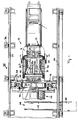
- FIG. 1 shows the molding section 2 downstream of a spray head 1, along which a plastic plastic tube emerging from the spray head 1 is cross-profiled becomes.
- complementary mold jaws are placed in pairs along the Forming section 2 performed on the machine table 4.
- the machine table 4 has a chassis 5, with which the machine table 4 in a bottom plate 6 anchored rails 7 can be moved. Like Figure 1 shows, the machine table 4 can move in the working direction of the spray head 1 become. A traversing drive for the machine table 4 can basically be different be trained. According to an advantageous embodiment, this can be a ball screw drive his.
- the machine table 4 is moved away from the spray head 1 Position shown. During operation, the machine table 4 is in accordance with Figure 1 move to the right so that those located on the machine table 4 Mold jaws 3 are retracted to the spray head 1.
- a cover frame 8 is arranged above the machine table 4. Like the figures 1 and 2 show, four columns 9 are anchored on the machine table 4, on which the Cover frame 8 is slidably mounted. The columns 9 are at their upper end connected to each other by a yoke 10. The yoke 10 is rigid on the columns 9 attached. In addition, the yoke 10 is arranged by means of two laterally arranged, transverse ones Tie rod 11 anchored to the machine table 4 to intercept the forces of the upper drive means arranged on the cover frame 8, which will be explained later be exercised. This avoids twisting of the columns 9.
- the cover frame 8 is slidable on the columns 9 stored. It is by means of four lifting spindles 12, each arranged on the columns 9 are supported and height adjustable.
- the associated lifting drive 53 is on the Arranged top of the yoke 10 and via suitable gear on the lifting spindles connected. The drive movement of the Lift actuator 53 synchronously transmitted to all lifting spindles (see FIG. 1).
- the cover frame can be relative to the columns 9 and relative to the
- the yoke 10 can be moved up and down, as particularly illustrated in FIG. 4.
- the cover frame 8 together with the yoke 10 and the one arranged thereon Superstructures lowered into a transport position towards the machine table 4 become.
- the columns 9 are designed to be telescopic. through Telescopic drives 13 in the form of lifting spindles can be telescoped together to each of the columns 9 become.
- Figure 4 are in the extended working position the columns 9 support cuffs 14 around an extended part of the columns 9 placed.
- the extended columns 9 can have a step-shaped heel 15, which also serves to link the lifting spindles to the support sleeves 14 are opened so that a precise and defined position of the columns 9 in extended state is reached.
- the upper part of the columns 9 can be lowered until the stepped shoulders 15 sit on the lower cylinders of the columns 9. With this additional drop the total height of the mold section device, which is denoted overall by 16, can be considerably reduced. Also the yoke 10 rigidly attached to the columns 9 with the superstructures located thereon is lowered accordingly. This facilitates the transportation of the molding line device 16 considerable. Before the yoke 10 is lowered, the yokes are attached to it To release tie rod 11.
- a main drive is used to advance the mold jaws 3 on the machine table 4 provided, the lower drive means 17, which are integrated in the machine table, and includes upper drive means 18 which are mounted on the cover frame 8.
- the lower drive means 17 have four drive pinions 19, each around horizontal axes can be driven transversely to the longitudinal direction of the molding section 2.
- the lower drive pinions 19 are combined in pairs and are from the side on the machine table 4 arranged drives 20 driven.
- the drives 20 are each coupled via a gear stage 21 to a drive shaft on which the Drive pinion 19 sit or are formed.
- the drives 20 are preferably can be removed from the machine table 4 to reduce its overall width during transport to be able to.
- the mold jaws to be driven on the machine table 4 have 2 on their underside, two racks 55, into which the lower drive pinions 19 can intervene.
- the lower drive means 17 are seated, as are the upper drive means 18, in the half of the machine table 4 facing the spray head 1, which, however, extends towards the spray head beyond the drive pinion, so that returned mold jaws placed on the machine table in front of the drive pinions can then be used with separate drive means, as explained below will be able to be pushed onto the drive pinion 19.
- the upper drive means 18 on the cover frame 8 comprise a pair of each other spaced upper drive pinion 22 driven about vertical axes of rotation can be (see Figure 4).
- the upper drive pinion 22 can be corresponding Drives and possibly gear stages are driven.
- the mold jaws 3 have racks 23 mounted on their upper sides are tilted into an upright arrangement so that their end face the circumference of the Drive pinion 22 is facing.
- the racks 23 on the Top of the mold jaws 3 oriented towards the outside, so that they are with you pair of complementary mold jaws 3 between the two drive pinions 22 run through it.
- the forces exerted by the drive pinions 22 thus act the mold jaws 3 closing.
- the special arrangement of the upper drive means 18 has the great advantage that thermal expansion of the mold jaws is permitted and are harmless to the drive. Between the racks 23 and the top Drive pinions 22 can have a certain offset in the vertical direction, without this hindering the advance of the mold jaws 3.
- a guide bar 29 is provided, which is preferably a T-shaped Can have profile.
- the mold jaws 3 have on their underside undercut guide projections 24 with which they guide the guide bar 29 can reach under the machine table 4. This will provide additional security reached. Additional guide rollers can also be attached to the machine table be provided.
- a longitudinal guide is also provided on the top of the mold jaws 3.
- 3 guide rollers can be on the cover frame 8 and the top of the mold jaws and an associated guide bar can be provided.
- the guides on the machine table 4 and on the cover frame 8 fork at the end the molding section V-shaped, so that the mold jaws at the end of the molding section be pushed apart and lifted off the corrugated pipe.
- the V-shaped fork 30 of the guides on the machine table 4 is shown in FIG. 1.
- Auxiliary feed means 31 are provided which are an insertion device for returned Form jaws 3 forms.
- the returned mold jaws 3 are at the front end of the machine table 4 placed on this so that they are not yet in engagement with the drive pinions 19 and 22, respectively.
- pneumatic cylinders 32 is provided, the working direction of which is parallel to the molding section 2.
- the pneumatic cylinders 32 are on the end frame connected to the machine table 4 56 arranged.
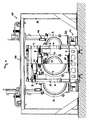
- FIG. 3 shows, on a cross member 33 of the end frame, that at the front end of the machine table 4 just above its surface is arranged, four pneumatic cylinders 32 are arranged.
- two further pneumatic cylinders 32 are arranged on an upper one Cross member 34 of the end frame 56.
- the pneumatic cylinder 32 When the pneumatic cylinder 32 is actuated, one on the front end of the machine table 4, a pair of molded jaws 3 to an already on the Form stretch 2 located, leading mold jaws are shot open.
- the pneumatic cylinders 32 push the mold jaw pair to be unlocked for this purpose against the leading pair of molded jaws.
- the pneumatic cylinders 32 have a dampening effect when unlocking and reduce a possible impact between the pair of mold jaws pushed and leading.
- a portal robot 35 is provided, which is fixed on the Base plate 6 is anchored and the molding section 2 or the molding section device 16 spanned.
- On both sides of the molding section 2 are each along one a plurality of supports 36 in the base plate parallel to the straight line 2 6 anchored. Two sit on the upper ends of the supports 36 to the molding section 2 parallel longitudinal beams 37, on which a spanning the molding section 2 Portal 38 is movably mounted.
- the portal 38 is flat.
- the portal 38 consists of two cross members 39 and 40.
- the portal 38 is in on stored in a known manner along the longitudinal beams 37 and movable.
- cross slides 41, 42 are seated on the portal 38, which run in opposite directions on the portal 38 are movable.
- the cross slides 41 and 42 can each be double be so that they sit on the cross members 39 and 40.
- Each of the cross slides 41 and 42 are associated with a slide drive 57, 58 for moving the slide.
- each of the cross slides 41 and 42 there is a gripper arm 43, 44 which is attached to the respective one Cross slide is mounted adjustable in height.
- Each of the gripper arms 43 and 44 is a lifting drive 45 and 46 assigned so that the gripping arms 43 and 44 independently can be raised and lowered vertically from the position of the slide.
- At the end of the gripping arms 43 and 44 are preferably form-fitting working Gripping devices provided, with the help of the mold jaws 3 on their upper sides, can be gripped in particular on corresponding bolt heads.
- the portal robot 35 grips a pair at the end of the Molding section 2 of shaped jaws 3 moved apart. This is preferably done during the spreading movement of the mold jaws 3 at the fork 30. Two-axis synchronization takes place for the portal robot to grip the mold jaws.
- the movement of the gripper arms 43 and 44 are both in The x-direction and the y-direction are synchronized with the movement of the mold jaws.
- the gripper arms of the gantry robot move exactly according to the Movement of the mold jaws along the fork 30. To compensate for position inaccuracies the mold jaws z. B.
- the gripping arms 43 and 44 sensors that are precise the relative position of the gripping devices on the gripping arms to the mold jaws, especially their bolt heads, especially in the last section of the Approach of the gripping devices to the mold jaws.
- the one connected to the sensors Control device can make appropriate corrections to the movement of the Arrange gripper arms and position inaccuracies of the mold jaws as a result of Compensate for thermal expansion and the like.
- the mold jaws 3 are lifted from the machine table 4 by the portal robot 35, moved laterally past the machine table 4 back to the beginning of the molding section and placed on the spray head end of the machine table 4 again. Placed on the machine table, the mold jaws 3 of the Pneumatic cylinders 32 pushed onto the leading pair of mold jaws and brought into engagement with the drive pinions 19 and 22.
- the machine table 4 is over the rear Mold jaw removal area in which the gantry robot 35 at the end of the molding section the mold jaws 3 engages, extended. He forms on his the spray head 1 opposite end a parking station 47 for special mold jaws such. B. socket mold jaws etc., which are only fed into the mold jaw cycle at the appropriate time Need to become.
- the portal robot 35 grabs this and places it at the front end of the Machine table 4 from.
- the parking station 47 advantageously lies directly on the machine table 4.
- the portal robot then simply grips the next pair of mold jaws 3 to get this back to the spray head end of the machine table to promote and drop there.
- the portal robot 35 takes care of the entry and exit.
- a change station 48 is provided in the base plate 6 in which a shuttle table 50 retractable and extendable is.
- the changing table 50 lies approximately at the end of the travel range of the machine table 4 when this has moved away from the spray head 1.
- the portal robot 35 takes retracted mold jaws from the changing table 50, around them at the end of the machine table 4 facing the spray head 1 to drop this.
- the portal robot takes the old mold jaws out 35 located at the end of the molding section 2 and puts them on the empty shuttle table 50.
- the changing table 50 is preferably of such a size that that at least a pair of mold jaws can be placed on it.
- the interaction between the machine table 4 or the entire molding section device 16 and the portal robot 35 separate therefrom is replaced by a central control device controlled.
- a position detection device is provided.
- the machine table 4 can preferably by means of a ball screw along the rails 7 anchored in the ground be moved.
- the ball screw or its drive is an absolute encoder assigned, which always precisely indicates the position of the machine table 4.
- the position device has an absolute encoder that drives the portal 38 is assigned. From this, the control device can always exactly the relative Determine the position of the molding line device and the portal robot in relation to one another.
- the control device can control the portal robot 35 in such a way that the mold jaws 3 during their movement on the machine table 4 attacks. The mold jaws 3 are therefore returned without any interruption of the process.
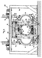
- FIG. 2 shows, there is a cooling device 51 or its on the upper cover frame 8 Docking agent 52 stored.
- the cooling device 51 has leak-free couplings, the coupling of the mold jaws 3 located on the molding section 2 to the Cooling device 51 allowed. Coolant channels are formed in the mold jaws 3 themselves, so that direct cooling of the mold jaws 3 is possible.
- the cooler 51 or their mold-side connections move with the mold jaws 3 as they move on the machine table 4 along the molding section 2 a piece of the distance, so that during the movement on the molding line 2 coolant can be circulated through the mold jaws 3. At the end of the molding line 2 uncouple the leak-free couplings of the cooling device 51.
- the Coolant remains in the mold jaws 3.
Landscapes
- Engineering & Computer Science (AREA)
- Mechanical Engineering (AREA)
- Manufacturing & Machinery (AREA)
- Moulds For Moulding Plastics Or The Like (AREA)
- Injection Moulding Of Plastics Or The Like (AREA)
- Extrusion Moulding Of Plastics Or The Like (AREA)
- Shaping Of Tube Ends By Bending Or Straightening (AREA)
Abstract
Description
- Fig. 1
- eine Draufsicht auf eine Wellrohranlage nach einem bevorzugten Ausführungsbeispiel der vorliegenden Erfindung, die einen fest am Boden installierten Portalroboter und eine auf Schienen verfahrbare Formstreckeneinrichtung mit Maschinentisch und daran befestigen Aufbauten zeigt,
- Fig. 2
- eine Seitenansicht der Wellrohranlage aus Figur 1, wobei die mobile Formstreckeneinrichtung von einem Spritzkopf weggefahren ist,
- Fig. 3
- eine Frontansicht der Formstreckeneinrichtung und des diese überspannenden Portalroboters von der Spritzkopfseite her, und
- Fig. 4
- eine Frontansicht der Wellrohranlage ähnlich Figur 3, wobei die Anlage in zwei Konfigurationen mit unterschiedlichen Formbackengrößen dargestellt ist.
Claims (17)
- Vorrichtung zur Herstellung von Wellrohren aus thermoplastischem Kunststoff, bei der in einem Kreislauf sich paarweise ergänzende Formbacken (3) gemeinsam entlang einer sich an einen Spritzkopf (1) anschließenden Formstrecke (2) geführt, am Ende der Formstrecke auseinandergefahren und separat voneinander zu deren Anfang zurückgeführt werden, mit einer Formstreckeneinrichtung (16) zur Bewegung der Formbacken entlang der Formstrecke und einem Rückförderer (35) zur Rückförderung der Formbacken (3) vom Ende der Formstrecke zu deren Anfang, wobei die Formstreckeneinrichtung (16) einen Maschinentisch (4) mit einer unteren Führung (29) und unteren Antriebsmitteln (17) für die Formbacken (3) und einen am Maschinentisch befestigten Deckrahmen (8) mit einer oberen Führung und oberen Antriebsmitteln (18) für die Formbacken aufweist, dadurch gekennzeichnet, daß die Formstreckeneinrichtung (16) und der Rückförderer (35) voneinander getrennte Einheiten bilden, wobei als Rückförderer ein an einer Bodenplatte (6) verankerter Portalroboter (35) vorgesehen und die Formstreckeneinheit (16) eine auf der Bodenplatte (6) verfahrbare Einheit ist.
- Vorrichtung nach dem vorhergehenden Anspruch, wobei eine Positionserfassungseinrichtung, insbesondere ein dem Maschinentisch (4) zugeordneter Absolutwertgeber, ein der entsprechenden Bewegungsachse des Portalroboters (35) zugeordneter Absolutwertgeber sowie ein den Antriebsmitteln zur Bewegung der Formbacken auf dem Maschinentisch zugeordneter Absolutwertgeber, zur Erfassung der Position des Maschinentisches (4) relativ zu dem Rückförderer (35), sowie eine mit der Positionserfassungseinrichtung verbundene zentrale Steuereinrichtung zur Ansteuerung der Formstreckeneinrichtung (16) und des Rückförderers (35) vorgesehen sind.
- Vorrichtung nach einem der vorhergehenden Ansprüchen, wobei der Portalroboter (35) ein ebenes Portal (38), das sich quer über die Formstrecke (2) erstreckt und parallel zu dieser verfahrbar ist, ein Paar Schlitten (41, 42), die an dem Portal gelagert und an diesem gegensinnig zueinander verfahrbar sind, sowie ein Paar an den Schlitten (41, 42) gelagerte Greifeinrichtungen (43, 44) aufweist, wobei die Greifeinrichtungen vertikal verfahrbar, insbesondere mittels eines Hubantriebs (45, 46) senkrecht zur Ebene des Maschinentischs (4) relativ zu dem jeweiligen Schlitten verfahrbar sind.
- Vorrichtung nach dem Oberbegriffs des Anspruchs 1, wobei die am Deckrahmen (8) gelagerten oberen Antriebsmittel (18) derart ausgebildet sind, daß sie eine Verschiebung der Formbacken (3) senkrecht zum Maschinentisch (4) zulassen, insbesondere um vertikale Achsen umlaufende Antriebsritzel (22) besitzen, die mit an den Formbacken (3) vorgesehenen Zahnstangen (23) zusammenwirken.
- Vorrichtung nach einem der vorhergehenden Ansprüche, wobei am Anfang der Formstrecke (2) von dem Rückförderer (35) separate Einschubmittel (32) zum Aufschließen eines rückgeführten Formbackenpaares (3) an bereits auf der Formstrecke befindliche, vorauseilende Formbacken (3) vorgesehen sind, wobei die Einschubmittel (32) eine Dämpfungseinrichtung zur Dämpfung der Vorschubbewegung beim Anstoßen der rückgeführten Formbacken an die vorauseilenden Formbacken aufweisen.
- Vorrichtung nach dem vorhergehenden Anspruch, wobei die Einschubmittel von zumindest einem am Maschinentisch (4) gelagerten Pneumatikzylinder (32) gebildet sind.
- Vorrichtung nach einem der vorhergehenden Ansprüche, wobei der Deckrahmen (8) relativ zum Maschinentisch (4) höhenverstellbar gelagert und mittels eines Hubantriebs (12) einstellbar ist.
- Vorrichtung nach einem der vorhergehenden Ansprüche, wobei der Deckrahmen (8) zum Maschinentisch (4) hin in eine Transportstellung absenkbar ausgebildet, vorzugsweise mittels motorisch teleskopierbarer, am Maschinentisch befestigter Säulen (9) abgestützt ist
- Vorrichtung nach dem Oberbegriff des Anspruchs 1, wobei eine Kühlvorrichtung (51) zur Kühlung der Formbacken (3) vorgesehen ist, die einen Kühlkreislauf und Andockmittel zum lösbaren Andocken des Kühlmittelkreislaufs an in den Formbacken ausgebildete Kühlmittelkanäle aufweist.
- Vorrichtung nach dem vorhergehenden Anspruch, wobei die Kühlvorrichtung (51) beweglich ausgebildete Kühlmittelleitungen, insbesondere -schläuchen, vorgesehen sind, derart, daß die angedockten Kühlmittelleitungen über eine Strecke mit den bewegten Formbacken (3) mitführbar sind.
- Vorrichtung nach einem der vorhergehenden Ansprüche, wobei formbackenseitige Kühlmittelkanäle und maschinentischseitige Kühlmittelleitungen mit leckagefreien Kupplungen versehen sind, die beim Andocken automatisch öffnen sowie beim Abdocken automatisch die formbackenseitigen Kühlmittelkanäle und die maschinentischseitigen Kühlmittelleitungen leckagefrei verschließen.
- Vorrichtung nach einem der vorhergehenden Ansprüche, wobei die Formbacken (3) Ausdehnspeicher besitzen, in die sich in formbackenseitigen Kühlmittelkanälen befindliches Kühlmittel ausdehnen kann.
- Vorrichtung nach einem der Ansprüche 9 bis 12, wobei die Kühlvorrichtung (51) gleichzeitig als Heizvorrichtung zum Vorheizen der Formbacken ausgebildet ist.
- Vorrichtung nach einem der vorhergehenden Ansprüche, wobei auf dem Maschinentisch am Ende der Formstrecke eine Parkstation (47) für Sonderformbacken wie Muffenformbacken und dergleichen vorgesehen ist.
- Vorrichtung nach einem der vorhergehenden Ansprüche, wobei am Ende der Formstrecke eine Wechselstation (48) zum Einspeisen neuer Formbacken und Ausspeisen alter Formbacken in den bzw. aus dem Formbackenkreislauf vorgesehen ist, wobei die Wechselstation (48) vorzugsweise einen verfahrbaren Wechseltisch (50) aufweist, der in den und aus dem Arbeitsbereich des Rückförderers (35), vorzugsweise an das dem Spritzkopf (1) abgewandte Ende des Maschinentischs (4) der Formstreckeneinrichtung (16), fahrbar ist.
- Vorrichtung nach dem vorhergehenden Anspruch, wobei in der Bodenplatte (6) Schienen (49) quer zur Richtung der Formstrecke im Bereich deren Endes vorgesehen sind, auf denen der Wechseltisch (50) verfahrbar ist.
- Vorrichtung nach einem der vorhergehenden Ansprüche, wobei in der Bodenplatte (6) Schienen (7) vorgesehen sind, auf denen die Formstreckeneinrichtung (16) vorzugsweise parallel zur Arbeitsrichtung des Spritzkopfes (1) verfahrbar ist.
Priority Applications (1)
| Application Number | Priority Date | Filing Date | Title |
|---|---|---|---|
| EP03029291A EP1407873B1 (de) | 2001-03-21 | 2001-12-14 | Vorrichtung zur Herstellung von Wellrohren |
Applications Claiming Priority (2)
| Application Number | Priority Date | Filing Date | Title |
|---|---|---|---|
| DE20104922U DE20104922U1 (de) | 2001-03-21 | 2001-03-21 | Wellrohranlage |
| DE20104922U | 2001-03-21 |
Related Child Applications (1)
| Application Number | Title | Priority Date | Filing Date |
|---|---|---|---|
| EP03029291A Division EP1407873B1 (de) | 2001-03-21 | 2001-12-14 | Vorrichtung zur Herstellung von Wellrohren |
Publications (3)
| Publication Number | Publication Date |
|---|---|
| EP1243400A2 true EP1243400A2 (de) | 2002-09-25 |
| EP1243400A3 EP1243400A3 (de) | 2004-03-31 |
| EP1243400B1 EP1243400B1 (de) | 2006-04-05 |
Family
ID=7954635
Family Applications (2)
| Application Number | Title | Priority Date | Filing Date |
|---|---|---|---|
| EP01129884A Expired - Lifetime EP1243400B1 (de) | 2001-03-21 | 2001-12-14 | Vorrichtung zum Herstellen von Wellrohren |
| EP03029291A Expired - Lifetime EP1407873B1 (de) | 2001-03-21 | 2001-12-14 | Vorrichtung zur Herstellung von Wellrohren |
Family Applications After (1)
| Application Number | Title | Priority Date | Filing Date |
|---|---|---|---|
| EP03029291A Expired - Lifetime EP1407873B1 (de) | 2001-03-21 | 2001-12-14 | Vorrichtung zur Herstellung von Wellrohren |
Country Status (8)
| Country | Link |
|---|---|
| US (1) | US7118369B2 (de) |
| EP (2) | EP1243400B1 (de) |
| JP (1) | JP2002307527A (de) |
| CN (1) | CN100418743C (de) |
| CA (1) | CA2377652C (de) |
| DE (3) | DE20104922U1 (de) |
| ES (1) | ES2257638T3 (de) |
| MX (1) | MXPA02002617A (de) |
Cited By (2)
| Publication number | Priority date | Publication date | Assignee | Title |
|---|---|---|---|---|
| DE102004040019B4 (de) * | 2004-08-18 | 2011-06-22 | Drossbach GmbH & Co. KG, 86641 | Vorrichtung zur Herstellung von Wellrohren |
| CN103057019A (zh) * | 2013-01-22 | 2013-04-24 | 桂林电器科学研究院 | 塑料厚膜拉伸生产线铸片用的风冷装置 |
Families Citing this family (22)
| Publication number | Priority date | Publication date | Assignee | Title |
|---|---|---|---|---|
| US8733405B2 (en) | 2005-03-14 | 2014-05-27 | Advanced Drainage Systems, Inc. | Corrugated pipe with outer layer |
| DE102006050543B4 (de) * | 2006-10-26 | 2008-08-21 | Drossbach Gmbh & Co. Kg | Vorrichtung zur Aufbringung von Kunststoff auf ein Werkstück |
| DE102007007139A1 (de) | 2007-02-09 | 2008-08-14 | Drossbach Gmbh & Co Kg | Vorrichtung zur Aufbringung von Kunststoff auf ein Werkstück |
| EP1916087A1 (de) | 2006-10-26 | 2008-04-30 | Drossbach GmbH & Co. KG | Vorrichtung zur Aufbringung von Kunststoff auf ein Werkstück |
| CA2622692C (en) | 2007-02-26 | 2015-10-06 | Advanced Drainage Systems, Inc. | Defined ratio dual-wall pipe die |
| CA2622695C (en) | 2007-02-26 | 2015-11-03 | Advanced Drainage Systems, Inc. | Pipe extrusion die flow path apparatus and method |
| DE102007049656A1 (de) * | 2007-10-12 | 2009-04-23 | Unicor Gmbh | Korrugatoreinrichtung mit Greifer |
| US8820800B2 (en) | 2007-11-16 | 2014-09-02 | Advanced Drainage Systems, Inc. | Multi-wall corrugated pipe couplings and methods |
| US8820801B2 (en) | 2007-11-16 | 2014-09-02 | Advanced Drainage System, Inc. | Multi-wall corrugated pipe couplings and methods |
| US8114324B2 (en) * | 2008-10-14 | 2012-02-14 | Advanced Drainage Systems, Inc. | Apparatus and method for pressing an outer wall of pipe |
| US7988438B2 (en) | 2008-02-11 | 2011-08-02 | Advanced Drainage Systems, Inc. | Extrusion die vacuum seals |
| US8550807B2 (en) | 2008-05-28 | 2013-10-08 | Advanced Drainage Systems, Inc. | In-mold punch apparatus and methods |
| CN103317695B (zh) * | 2013-04-12 | 2015-06-17 | 大连三垒机器股份有限公司 | 波纹管成型机工作台的调整装置 |
| CA2852557C (en) * | 2014-05-20 | 2022-04-05 | Manfred A. A. Lupke | System and method for identifying thermal expansion issues in a corrugator |
| CN104772783B (zh) * | 2015-01-23 | 2022-11-01 | 东阳市沃特塑胶有限公司 | 一种伸缩管自动压缩切割机 |
| DE102016112421B4 (de) * | 2016-07-06 | 2021-10-21 | Schlemmer Gmbh | Corrugator, Extrusionsanlage sowie Verfahren |
| CN108515645A (zh) * | 2018-05-07 | 2018-09-11 | 扬州乾昇机械有限公司 | 一种可自动整理并转运软管的工装设备 |
| CN108790054A (zh) * | 2018-08-24 | 2018-11-13 | 阜阳裕晟电子科技有限公司 | 一种汽车方向盘上护罩模具 |
| KR102096350B1 (ko) * | 2019-09-02 | 2020-04-02 | 이경노 | 내·외관 일체형 보호관의 성형장치 및 그 보호관 |
| CN111070651B (zh) * | 2019-12-20 | 2022-01-11 | 伊书剑 | 一种花园水管用的护套制褶机构及其使用方法 |
| CN111196000B (zh) * | 2020-01-10 | 2021-09-21 | 韩前旗 | 用于塑料软管的可调式万能成型工装或验具的使用方法 |
| CN112677447B (zh) * | 2020-12-10 | 2022-07-12 | 潍坊中云科研有限公司 | 可选扩口的波纹管成型机 |
Family Cites Families (12)
| Publication number | Priority date | Publication date | Assignee | Title |
|---|---|---|---|---|
| DE2832350A1 (de) * | 1978-07-22 | 1980-01-31 | Wilhelm Hegler | Vorrichtung zur herstellung von rohren aus thermoplastischem kunststoff mit querprofilierung |
| DE3120480A1 (de) * | 1981-05-22 | 1982-12-09 | Hegler, Wilhelm, 8730 Bad Kissingen | Vorrichtung zur herstellung von kunststoffrohren mit querrillen |
| ES2019279B3 (es) * | 1986-11-13 | 1991-06-16 | Unicor Gmbh Rahn Plastmaschinen | Dispositivo para la fabricacion continua de tubos con paredes perfiladas transversales |
| AU686094B2 (en) * | 1992-09-25 | 1998-02-05 | Big 'o' Inc. | Method and apparatus for production of tubing |
| WO1994007673A1 (en) * | 1992-09-25 | 1994-04-14 | Big 'o' Inc. | Apparatus and method for the production of thermoplastic pipe or tubing |
| US5489201A (en) * | 1993-04-15 | 1996-02-06 | Cullom Machine Tool & Die, Inc. | Plastic tile corrugator and mold blocks |
| DE4318514C1 (de) * | 1993-06-03 | 1994-08-18 | Drossbach Gmbh & Co Kg | Vorrichtung zum Herstellen von Wellrohren aus thermoplastischem Kunststoff |
| DE9311140U1 (de) * | 1993-07-26 | 1993-09-09 | Drossbach GmbH & Co KG, 86641 Rain | Vorrichtung zum Herstellen von Wellrohren aus thermoplastischem Kunststoff |
| CA2077872C (en) * | 1993-12-20 | 1998-06-09 | Manfred A. A. Lupke | Apparatus for making annularly ribbed plastic pipe and method of making such pipe |
| DE4414977A1 (de) * | 1994-04-29 | 1995-11-02 | Wilhelm Hegler | Vorrichtung zur Herstellung von Rohren aus thermoplastischem Kunststoff mit Querprofilierung |
| DE19535231A1 (de) * | 1995-09-22 | 1997-03-27 | Hegler Ralph Peter | Vorrichtung zur Herstellung von Rohren aus thermoplastischem Kunststoff mit Querprofilierung |
| US7001171B2 (en) * | 2001-02-19 | 2006-02-21 | Starita Joseph M | Apparatus and methods for managing molds and forming transverse corrugations and other shapes in extruded tubular polymer melt parisons |
-
2001
- 2001-03-21 DE DE20104922U patent/DE20104922U1/de not_active Expired - Lifetime
- 2001-12-14 EP EP01129884A patent/EP1243400B1/de not_active Expired - Lifetime
- 2001-12-14 EP EP03029291A patent/EP1407873B1/de not_active Expired - Lifetime
- 2001-12-14 ES ES03029291T patent/ES2257638T3/es not_active Expired - Lifetime
- 2001-12-14 DE DE50109431T patent/DE50109431D1/de not_active Expired - Lifetime
- 2001-12-14 DE DE50109023T patent/DE50109023D1/de not_active Expired - Lifetime
-
2002
- 2002-02-25 JP JP2002048356A patent/JP2002307527A/ja active Pending
- 2002-03-11 MX MXPA02002617A patent/MXPA02002617A/es unknown
- 2002-03-20 US US10/103,164 patent/US7118369B2/en not_active Expired - Fee Related
- 2002-03-20 CA CA002377652A patent/CA2377652C/en not_active Expired - Fee Related
- 2002-03-21 CN CNB021078092A patent/CN100418743C/zh not_active Expired - Fee Related
Cited By (3)
| Publication number | Priority date | Publication date | Assignee | Title |
|---|---|---|---|---|
| DE102004040019B4 (de) * | 2004-08-18 | 2011-06-22 | Drossbach GmbH & Co. KG, 86641 | Vorrichtung zur Herstellung von Wellrohren |
| US8167603B2 (en) | 2004-08-18 | 2012-05-01 | Drossbach Gmbh & Co. Kg | Device for the production of corrugated pipes |
| CN103057019A (zh) * | 2013-01-22 | 2013-04-24 | 桂林电器科学研究院 | 塑料厚膜拉伸生产线铸片用的风冷装置 |
Also Published As
| Publication number | Publication date |
|---|---|
| JP2002307527A (ja) | 2002-10-23 |
| CA2377652C (en) | 2009-06-23 |
| EP1243400A3 (de) | 2004-03-31 |
| DE50109431D1 (de) | 2006-05-18 |
| ES2257638T3 (es) | 2006-08-01 |
| DE20104922U1 (de) | 2002-07-25 |
| DE50109023D1 (de) | 2006-04-27 |
| US20020136791A1 (en) | 2002-09-26 |
| EP1243400B1 (de) | 2006-04-05 |
| CA2377652A1 (en) | 2002-09-21 |
| CN100418743C (zh) | 2008-09-17 |
| MXPA02002617A (es) | 2004-11-12 |
| CN1383975A (zh) | 2002-12-11 |
| US7118369B2 (en) | 2006-10-10 |
| EP1407873B1 (de) | 2006-02-22 |
| EP1407873A1 (de) | 2004-04-14 |
Similar Documents
| Publication | Publication Date | Title |
|---|---|---|
| EP1407873A1 (de) | Vorrichtung zur Herstellung von Wellrohren | |
| EP3268144B1 (de) | Richtmaschine und verfahren zum wechseln von richtrollenelementen | |
| EP2118406B1 (de) | Parkanlage für kraftfahrzeuge und verfahren zum betrieb derselben | |
| EP1935811B1 (de) | Luftförderer für Behältnisse | |
| EP0764516A2 (de) | Vorrichtung zur Herstellung von Rohren aus thermoplastischem Kunststoff mit Querprofilierung | |
| DE102004040019B4 (de) | Vorrichtung zur Herstellung von Wellrohren | |
| EP0671228B1 (de) | Transporteinrichtung für Werkstücke in einer Presse | |
| DE4408449A1 (de) | Transportsystem | |
| DE19914974C2 (de) | Wechselcorrugator | |
| EP0759331B1 (de) | Vorrichtung zum schrittweisen Quertransport von Profilen zwischen dem Auslauf einer Metallstrangpresse und einer Streckrichtmaschine | |
| EP0901848B1 (de) | Transferpressen mit automatischem Toolingwechsel | |
| EP0246398B1 (de) | Giessformwechseleinrichtung an einer Gruppe von Kunststoff-Spritzgiessmaschinen | |
| DE10162282B4 (de) | Transfervorrichtung zum Transport von Formteilen zwischen Pressen mit oder ohne Zwischenstation | |
| EP1238780B1 (de) | Verfahren und Vorrichtung zur Herstellung von Rohren aus thermoplastischem Kunststoff mit Querprofilierung | |
| DE102005015580B4 (de) | Spannmodul | |
| DE69015042T2 (de) | Spritzstreckblasverfahren und -vorrichtung. | |
| DE69621443T2 (de) | Verbesserte spannrahmen-wechselvorrichtung | |
| DE19851746A1 (de) | Modularer Transfer mit Schwenk- und Linearantrieben | |
| DE102004015739B4 (de) | Transportvorrichtung | |
| DE3940127C2 (de) | Querverschiebeantrieb für einen Transportwagen zum automatischen Formwerkzeugwechsel bei Spritzgießmaschinen | |
| EP1053857A2 (de) | Blasformmaschine für das abfallarme Blasen | |
| DE4041593A1 (de) | Vorrichtung und verfahren zum ansammeln von kontinuierlich transportierten teilen | |
| DE3644915A1 (de) | Einrichtung zum abtransport der spritzlinge an einer gruppe von kunststoff-spritzgiessmaschinen | |
| DE202005021219U1 (de) | Vorrichtung zur Herstellung von Wellrohren | |
| EP3081330B1 (de) | Vorrichtung zum einsetzen von werkstücken oder werkzeugen in eine werkzeugmaschine |
Legal Events
| Date | Code | Title | Description |
|---|---|---|---|
| PUAI | Public reference made under article 153(3) epc to a published international application that has entered the european phase |
Free format text: ORIGINAL CODE: 0009012 |
|
| AK | Designated contracting states |
Kind code of ref document: A2 Designated state(s): AT BE CH CY DE DK ES FI FR GB GR IE IT LI LU MC NL PT SE TR |
|
| AX | Request for extension of the european patent |
Free format text: AL;LT;LV;MK;RO;SI |
|
| PUAL | Search report despatched |
Free format text: ORIGINAL CODE: 0009013 |
|
| 17P | Request for examination filed |
Effective date: 20040108 |
|
| AK | Designated contracting states |
Kind code of ref document: A3 Designated state(s): AT BE CH CY DE DK ES FI FR GB GR IE IT LI LU MC NL PT SE TR |
|
| AX | Request for extension of the european patent |
Extension state: AL LT LV MK RO SI |
|
| 17Q | First examination report despatched |
Effective date: 20040324 |
|
| AKX | Designation fees paid |
Designated state(s): DE ES FR GB IT |
|
| GRAP | Despatch of communication of intention to grant a patent |
Free format text: ORIGINAL CODE: EPIDOSNIGR1 |
|
| GRAS | Grant fee paid |
Free format text: ORIGINAL CODE: EPIDOSNIGR3 |
|
| GRAA | (expected) grant |
Free format text: ORIGINAL CODE: 0009210 |
|
| AK | Designated contracting states |
Kind code of ref document: B1 Designated state(s): DE ES FR GB IT |
|
| PG25 | Lapsed in a contracting state [announced via postgrant information from national office to epo] |
Ref country code: GB Free format text: LAPSE BECAUSE OF FAILURE TO SUBMIT A TRANSLATION OF THE DESCRIPTION OR TO PAY THE FEE WITHIN THE PRESCRIBED TIME-LIMIT Effective date: 20060405 |
|
| REG | Reference to a national code |
Ref country code: GB Ref legal event code: FG4D Free format text: NOT ENGLISH |
|
| REF | Corresponds to: |
Ref document number: 50109431 Country of ref document: DE Date of ref document: 20060518 Kind code of ref document: P |
|
| PG25 | Lapsed in a contracting state [announced via postgrant information from national office to epo] |
Ref country code: ES Free format text: LAPSE BECAUSE OF FAILURE TO SUBMIT A TRANSLATION OF THE DESCRIPTION OR TO PAY THE FEE WITHIN THE PRESCRIBED TIME-LIMIT Effective date: 20060716 |
|
| GBV | Gb: ep patent (uk) treated as always having been void in accordance with gb section 77(7)/1977 [no translation filed] |
Effective date: 20060405 |
|
| PLBE | No opposition filed within time limit |
Free format text: ORIGINAL CODE: 0009261 |
|
| STAA | Information on the status of an ep patent application or granted ep patent |
Free format text: STATUS: NO OPPOSITION FILED WITHIN TIME LIMIT |
|
| 26N | No opposition filed |
Effective date: 20070108 |
|
| EN | Fr: translation not filed | ||
| PG25 | Lapsed in a contracting state [announced via postgrant information from national office to epo] |
Ref country code: FR Free format text: LAPSE BECAUSE OF FAILURE TO SUBMIT A TRANSLATION OF THE DESCRIPTION OR TO PAY THE FEE WITHIN THE PRESCRIBED TIME-LIMIT Effective date: 20070309 |
|
| PG25 | Lapsed in a contracting state [announced via postgrant information from national office to epo] |
Ref country code: FR Free format text: LAPSE BECAUSE OF FAILURE TO SUBMIT A TRANSLATION OF THE DESCRIPTION OR TO PAY THE FEE WITHIN THE PRESCRIBED TIME-LIMIT Effective date: 20060405 |
|
| PGFP | Annual fee paid to national office [announced via postgrant information from national office to epo] |
Ref country code: IT Payment date: 20100527 Year of fee payment: 9 |
|
| PG25 | Lapsed in a contracting state [announced via postgrant information from national office to epo] |
Ref country code: IT Free format text: LAPSE BECAUSE OF NON-PAYMENT OF DUE FEES Effective date: 20101214 |
|
| REG | Reference to a national code |
Ref country code: DE Country of ref document: DE Ref legal event code: R082 Ref document number: 50109431 Representative=s name: MEYER & PARTNER GBR, DE |
|
| REG | Reference to a national code |
Ref country code: DE Ref legal event code: R081 Ref document number: 50109431 Country of ref document: DE Owner name: SIEGFRIED MEYER BAKUM GMBH & CO. KG, DE Free format text: FORMER OWNER: DROSSBACH GMBH & CO. KG, 86641 RAIN, DE Effective date: 20130416 Ref country code: DE Ref legal event code: R082 Ref document number: 50109431 Country of ref document: DE Representative=s name: MEYER & PARTNER GBR, DE Effective date: 20120921 |
|
| PGFP | Annual fee paid to national office [announced via postgrant information from national office to epo] |
Ref country code: DE Payment date: 20151127 Year of fee payment: 15 |
|
| REG | Reference to a national code |
Ref country code: DE Ref legal event code: R119 Ref document number: 50109431 Country of ref document: DE |
|
| PG25 | Lapsed in a contracting state [announced via postgrant information from national office to epo] |
Ref country code: DE Free format text: LAPSE BECAUSE OF NON-PAYMENT OF DUE FEES Effective date: 20170701 |