EP1243667A2 - Méthode et appareil de controle de flux de recirculation d'un gas pour système de fabrication de semiconducteur sous vide - Google Patents
Méthode et appareil de controle de flux de recirculation d'un gas pour système de fabrication de semiconducteur sous vide Download PDFInfo
- Publication number
- EP1243667A2 EP1243667A2 EP02006584A EP02006584A EP1243667A2 EP 1243667 A2 EP1243667 A2 EP 1243667A2 EP 02006584 A EP02006584 A EP 02006584A EP 02006584 A EP02006584 A EP 02006584A EP 1243667 A2 EP1243667 A2 EP 1243667A2
- Authority
- EP
- European Patent Office
- Prior art keywords
- gas
- pressure
- vacuum chamber
- gas recirculation
- vacuum pump
- Prior art date
- Legal status (The legal status is an assumption and is not a legal conclusion. Google has not performed a legal analysis and makes no representation as to the accuracy of the status listed.)
- Withdrawn
Links
Images


Classifications
-
- C—CHEMISTRY; METALLURGY
- C23—COATING METALLIC MATERIAL; COATING MATERIAL WITH METALLIC MATERIAL; CHEMICAL SURFACE TREATMENT; DIFFUSION TREATMENT OF METALLIC MATERIAL; COATING BY VACUUM EVAPORATION, BY SPUTTERING, BY ION IMPLANTATION OR BY CHEMICAL VAPOUR DEPOSITION, IN GENERAL; INHIBITING CORROSION OF METALLIC MATERIAL OR INCRUSTATION IN GENERAL
- C23C—COATING METALLIC MATERIAL; COATING MATERIAL WITH METALLIC MATERIAL; SURFACE TREATMENT OF METALLIC MATERIAL BY DIFFUSION INTO THE SURFACE, BY CHEMICAL CONVERSION OR SUBSTITUTION; COATING BY VACUUM EVAPORATION, BY SPUTTERING, BY ION IMPLANTATION OR BY CHEMICAL VAPOUR DEPOSITION, IN GENERAL
- C23C16/00—Chemical coating by decomposition of gaseous compounds, without leaving reaction products of surface material in the coating, i.e. chemical vapour deposition [CVD] processes
- C23C16/44—Chemical coating by decomposition of gaseous compounds, without leaving reaction products of surface material in the coating, i.e. chemical vapour deposition [CVD] processes characterised by the method of coating
- C23C16/455—Chemical coating by decomposition of gaseous compounds, without leaving reaction products of surface material in the coating, i.e. chemical vapour deposition [CVD] processes characterised by the method of coating characterised by the method used for introducing gases into reaction chamber or for modifying gas flows in reaction chamber
- C23C16/45593—Recirculation of reactive gases
-
- H—ELECTRICITY
- H10—SEMICONDUCTOR DEVICES; ELECTRIC SOLID-STATE DEVICES NOT OTHERWISE PROVIDED FOR
- H10P—GENERIC PROCESSES OR APPARATUS FOR THE MANUFACTURE OR TREATMENT OF DEVICES COVERED BY CLASS H10
- H10P95/00—Generic processes or apparatus for manufacture or treatments not covered by the other groups of this subclass
-
- C—CHEMISTRY; METALLURGY
- C23—COATING METALLIC MATERIAL; COATING MATERIAL WITH METALLIC MATERIAL; CHEMICAL SURFACE TREATMENT; DIFFUSION TREATMENT OF METALLIC MATERIAL; COATING BY VACUUM EVAPORATION, BY SPUTTERING, BY ION IMPLANTATION OR BY CHEMICAL VAPOUR DEPOSITION, IN GENERAL; INHIBITING CORROSION OF METALLIC MATERIAL OR INCRUSTATION IN GENERAL
- C23C—COATING METALLIC MATERIAL; COATING MATERIAL WITH METALLIC MATERIAL; SURFACE TREATMENT OF METALLIC MATERIAL BY DIFFUSION INTO THE SURFACE, BY CHEMICAL CONVERSION OR SUBSTITUTION; COATING BY VACUUM EVAPORATION, BY SPUTTERING, BY ION IMPLANTATION OR BY CHEMICAL VAPOUR DEPOSITION, IN GENERAL
- C23C16/00—Chemical coating by decomposition of gaseous compounds, without leaving reaction products of surface material in the coating, i.e. chemical vapour deposition [CVD] processes
- C23C16/44—Chemical coating by decomposition of gaseous compounds, without leaving reaction products of surface material in the coating, i.e. chemical vapour deposition [CVD] processes characterised by the method of coating
- C23C16/4412—Details relating to the exhausts, e.g. pumps, filters, scrubbers, particle traps
-
- Y—GENERAL TAGGING OF NEW TECHNOLOGICAL DEVELOPMENTS; GENERAL TAGGING OF CROSS-SECTIONAL TECHNOLOGIES SPANNING OVER SEVERAL SECTIONS OF THE IPC; TECHNICAL SUBJECTS COVERED BY FORMER USPC CROSS-REFERENCE ART COLLECTIONS [XRACs] AND DIGESTS
- Y10—TECHNICAL SUBJECTS COVERED BY FORMER USPC
- Y10S—TECHNICAL SUBJECTS COVERED BY FORMER USPC CROSS-REFERENCE ART COLLECTIONS [XRACs] AND DIGESTS
- Y10S438/00—Semiconductor device manufacturing: process
- Y10S438/909—Controlled atmosphere
-
- Y—GENERAL TAGGING OF NEW TECHNOLOGICAL DEVELOPMENTS; GENERAL TAGGING OF CROSS-SECTIONAL TECHNOLOGIES SPANNING OVER SEVERAL SECTIONS OF THE IPC; TECHNICAL SUBJECTS COVERED BY FORMER USPC CROSS-REFERENCE ART COLLECTIONS [XRACs] AND DIGESTS
- Y10—TECHNICAL SUBJECTS COVERED BY FORMER USPC
- Y10T—TECHNICAL SUBJECTS COVERED BY FORMER US CLASSIFICATION
- Y10T137/00—Fluid handling
- Y10T137/0318—Processes
- Y10T137/0324—With control of flow by a condition or characteristic of a fluid
- Y10T137/0379—By fluid pressure
-
- Y—GENERAL TAGGING OF NEW TECHNOLOGICAL DEVELOPMENTS; GENERAL TAGGING OF CROSS-SECTIONAL TECHNOLOGIES SPANNING OVER SEVERAL SECTIONS OF THE IPC; TECHNICAL SUBJECTS COVERED BY FORMER USPC CROSS-REFERENCE ART COLLECTIONS [XRACs] AND DIGESTS
- Y10—TECHNICAL SUBJECTS COVERED BY FORMER USPC
- Y10T—TECHNICAL SUBJECTS COVERED BY FORMER US CLASSIFICATION
- Y10T137/00—Fluid handling
- Y10T137/0318—Processes
- Y10T137/0396—Involving pressure control
-
- Y—GENERAL TAGGING OF NEW TECHNOLOGICAL DEVELOPMENTS; GENERAL TAGGING OF CROSS-SECTIONAL TECHNOLOGIES SPANNING OVER SEVERAL SECTIONS OF THE IPC; TECHNICAL SUBJECTS COVERED BY FORMER USPC CROSS-REFERENCE ART COLLECTIONS [XRACs] AND DIGESTS
- Y10—TECHNICAL SUBJECTS COVERED BY FORMER USPC
- Y10T—TECHNICAL SUBJECTS COVERED BY FORMER US CLASSIFICATION
- Y10T137/00—Fluid handling
- Y10T137/8593—Systems
- Y10T137/85954—Closed circulating system
-
- Y—GENERAL TAGGING OF NEW TECHNOLOGICAL DEVELOPMENTS; GENERAL TAGGING OF CROSS-SECTIONAL TECHNOLOGIES SPANNING OVER SEVERAL SECTIONS OF THE IPC; TECHNICAL SUBJECTS COVERED BY FORMER USPC CROSS-REFERENCE ART COLLECTIONS [XRACs] AND DIGESTS
- Y10—TECHNICAL SUBJECTS COVERED BY FORMER USPC
- Y10T—TECHNICAL SUBJECTS COVERED BY FORMER US CLASSIFICATION
- Y10T137/00—Fluid handling
- Y10T137/8593—Systems
- Y10T137/85978—With pump
- Y10T137/86083—Vacuum pump
Definitions
- the present invention relates to a gas recirculation flow control method and apparatus for use in an evacuation system for introducing a process gas into a vacuum chamber of semiconductor manufacturing equipment or the like and exhausting the process gas from the vacuum chamber.
- the gas recirculation flow control method and apparatus control the recirculation flow rate of the gas exhausted from the vacuum chamber and returned thereto through a gas recirculation line.
- a gas is introduced into a vacuum chamber, and the gas is exhausted by reducing the pressure in the vacuum chamber to a desired pressure with a vacuum pump.
- the amount of gas used in such semiconductor manufacturing equipment is increasing.
- only a part of the gas introduced into the vacuum chamber contributes to the desired reaction.
- the rest of the gas, which accounts for a greater part of the introduced gas is exhausted as it is without reacting.
- a gas recirculation process wherein a part of gas exhausted from the vacuum chamber is returned to the vacuum chamber is carried out for the purpose of increasing the utilization efficiency of the unreacted gas.
- the flow rate of the gas recirculating in the gas recirculation process i.e. recirculation ratio
- Fig. 1 is a diagram showing a structural example of an evacuation system in which the flow rate of a recirculating gas is controlled by directly measuring the recirculating gas flow rate using a mass flow controller as stated above.
- the evacuation system includes a vacuum chamber 1 into which a gas is introduced.
- the vacuum chamber 1 has a shower head 2.
- the evacuation system further includes an adaptive pressure control valve 3, a first vacuum pump suction-side gate valve 4, a first vacuum pump 5, a second vacuum pump suction-side gate valve 6, a second vacuum pump 7, a gas recirculation line 8, a gas recirculation line gate valve (on-off valve) 9, a mass flow controller 10, a first pressure sensor 11 for detecting the pressure in the vacuum chamber 1, and a second pressure sensor 12 for detecting the pressure in the upstream side of the gas recirculation line 8.
- an adaptive pressure control valve 3 a first vacuum pump suction-side gate valve 4, a first vacuum pump 5, a second vacuum pump suction-side gate valve 6, a second vacuum pump 7, a gas recirculation line 8, a gas recirculation line gate valve (on-off valve) 9, a mass flow controller 10, a first pressure sensor 11 for detecting the pressure in the vacuum chamber 1, and a second pressure sensor 12 for detecting the pressure in the upstream side of the gas recirculation line 8.
- a gas G 1 is introduced into the vacuum chamber 1 through the shower head 2 at a flow rate Q 1 .
- the introduced gas is exhausted by the first vacuum pump 5 to reduce the pressure in the vacuum chamber 1 to a desired pressure.
- the first vacuum pump 5 is evacuated by the second vacuum pump 7 to lower the back pressure of the first vacuum pump 5 below an allowable back pressure.
- a part of gas G 2 exhausted from the first vacuum pump 5 is returned to the vacuum chamber 1 through the gas recirculation line 8.
- the recirculation flow rate Q 2 of gas returned to the vacuum chamber 1 is measured by the mass flow controller 10 provided in the gas recirculation line 8 and is controlled by varying the effective pumping speeds of the first vacuum pump 5 and the second vacuum pump 7, etc. on the basis of the measured flow rate Q 2 .
- the flow rate of the recirculating gas G 2 is measured directly with a mass flow controller.
- This method needs a differential pressure of more than about 50 kPa for the operation of the mass flow controller.
- the differential pressure in the gas recirculation line 8 is not more than 50 kPa. Accordingly, a mass flow controller cannot be used to control the flow rate of the recirculating gas, depending upon the type of evacuation system to which the control method is applied.
- the present invention was made in view of the above-described circumstances.
- An object of the present invention is to provide a gas recirculation flow control method and apparatus for use in an evacuation system, which are simple in arrangement and capable of readily controlling the recirculation flow rate of a gas returning to a vacuum chamber through a gas recirculation line even when the differential pressure in the gas recirculation line is not greater than the working pressure of a mass flow controller used (i.e. not more than 50 kPa).
- a gas recirculation flow control method for use in an evacuation system having a vacuum chamber into which a gas is introduced.
- the evacuation system further has a first vacuum pump for exhausting the gas from the vacuum chamber and reducing the pressure in the vacuum chamber to a desired pressure, a second vacuum pump for performing evacuation to lower the back pressure of the first vacuum pump below an allowable back pressure, and a gas recirculation line for returning a part of gas exhausted from the first vacuum pump to the vacuum chamber.
- the gas recirculation flow rate Q 2 can be controlled simply by adjusting the differential pressure Pd-Pc in the gas recirculation line by varying the effective pumping speed of the second vacuum pump.
- a gas recirculation flow control method for use in an evacuation system having a vacuum chamber into which a gas is introduced.
- the evacuation system further has a first vacuum pump for exhausting the gas from the vacuum chamber and reducing the pressure in the vacuum chamber to a desired pressure, a second vacuum pump for performing evacuation to lower the back pressure of the first vacuum pump below an allowable back pressure, and a gas recirculation line for returning a part of gas exhausted from the first vacuum pump to the vacuum chamber.
- the gas recirculation flow rate Q 2 can be controlled simply by adjusting the differential pressure Pd-Pc in the gas recirculation line by varying the flow rate of the purge gas introduced upstream or inside the second vacuum pump.
- a gas recirculation flow control method for use in an evacuation system having a vacuum chamber into which a gas is introduced.
- the evacuation system further has a first vacuum pump for exhausting the gas from the vacuum chamber and reducing the pressure in the vacuum chamber to a desired pressure, a second vacuum pump for performing evacuation to lower the back pressure of the first vacuum pump below an allowable back pressure, and a gas recirculation line for returning a part of gas exhausted from the first vacuum pump to the vacuum chamber.
- the gas recirculation flow rate Q 2 can be controlled simply by introducing the gas at the total flow rate Qt, adjusting the effective pumping speed of the first vacuum pump, adjusting the flow rate of the introduced gas. and adjusting the effective pumping speed of the second vacuum pump.
- a gas recirculation flow control method for use in an evacuation system having a vacuum chamber into which a gas is introduced.
- the evacuation system further has a first vacuum pump for exhausting the gas from the vacuum chamber and reducing the pressure in the vacuum chamber to a desired pressure, a second vacuum pump for performing evacuation to lower the back pressure of the first vacuum pump below an allowable back pressure, and a gas recirculation line for returning a part of gas exhausted from the first vacuum pump to the vacuum chamber.
- the gas recirculation flow rate Q 2 can be controlled simply by introducing the gas at the total flow rate Qt, adjusting the effective pumping speed of the first vacuum pump, and adjusting the flow rate of the purge gas.
- the effective pumping speed of the second vacuum pump may be adjusted by a conductance control device provided upstream of the second vacuum pump.
- the effective pumping speed of the second vacuum pump may be adjusted by varying the number of revolutions of the second vacuum pump.
- the present invention provides a gas recirculation flow control apparatus for use in an evacuation system having a vacuum chamber into which a gas is introduced.
- the evacuation system further has a first vacuum pump for exhausting the gas from the vacuum chamber and reducing the pressure in the vacuum chamber to a desired pressure, a second vacuum pump for performing evacuation to lower the back pressure of the first vacuum pump below an allowable back pressure, a gas recirculation line for returning a part of gas exhausted from the first vacuum pump to the vacuum chamber, a first pressure sensor for detecting the pressure in the vacuum chamber, and a second pressure sensor for detecting the pressure in the upstream side of the gas recirculation line.
- the gas recirculation flow control device can control the gas recirculation flow rate Q 2 simply by adjusting the differential pressure Pd-Pc in the gas recirculation line, which is detected with the first and second pressure sensors, by varying the effective pumping speed of the second vacuum pump.
- the present invention provides a gas recirculation flow control apparatus for use in an evacuation system having a vacuum chamber into which a gas is introduced.
- the evacuation system further has a first vacuum pump for exhausting the gas from the vacuum chamber and reducing the pressure in the vacuum chamber to a desired pressure, a second vacuum pump for performing evacuation to lower the back pressure of the first vacuum pump below an allowable back pressure, a gas recirculation line for returning a part of gas exhausted from the first vacuum pump to the vacuum chamber, a first pressure sensor for detecting the pressure in the vacuum chamber, and a second pressure sensor for detecting the pressure in the upstream side of the gas recirculation line.
- the gas recirculation flow control device can control the gas recirculation flow rate Q 2 simply by adjusting the differential pressure Pd-Pc in the gas recirculation line, which is detected with the first and second pressure sensors, by varying the purge gas flow rate.
- the present invention provides a gas recirculation flow control apparatus for use in an evacuation system having a vacuum chamber into which a gas is introduced.
- the evacuation system further has a first vacuum pump for exhausting the gas from the vacuum chamber and reducing the pressure in the vacuum chamber to a desired pressure, a second vacuum pump for performing evacuation to lower the back pressure of the first vacuum pump below an allowable back pressure, a gas recirculation line for returning a part of gas exhausted from the first vacuum pump to the vacuum chamber, a first pressure sensor for detecting the pressure in the vacuum chamber, a second pressure sensor for detecting the pressure in the upstream side of the gas recirculation line, and an on-off valve for selectively opening and closing the gas recirculation line.
- the gas recirculation flow control device can control the gas recirculation flow rate Q 2 simply by on-off controlling the on-off valve, monitoring the pressure detected with the first pressure sensor, adjusting the flow rate of the gas introduced into the vacuum chamber, and adjusting the effective pumping speeds of the first and second vacuum pumps.
- the present invention provides a gas recirculation flow control apparatus for use in an evacuation system having a vacuum chamber into which a gas is introduced.
- the evacuation system further has a first vacuum pump for exhausting the gas from the vacuum chamber and reducing the pressure in the vacuum chamber to a desired pressure, a second vacuum pump for performing evacuation to lower the back pressure of the first vacuum pump below an allowable back pressure, a gas recirculation line for returning a part of gas exhausted from the first vacuum pump to the vacuum chamber, a first pressure sensor for detecting the pressure in the vacuum chamber, a second pressure sensor for detecting the pressure in the upstream side of the gas recirculation line, and an on-off valve for selectively opening and closing the gas recirculation line.
- the gas recirculation flow control device can control the gas recirculation flow rate Q 2 simply by on-off controlling the on-off valve, monitoring the pressure detected with the first pressure sensor, adjusting the flow rate of the gas introduced into the vacuum chamber, adjusting the effective pumping speed of the first vacuum pump, and adjusting the purge gas flow rate.
- the gas recirculation flow control device preferably has the function of automatically performing an operation for controlling the recirculation flow rate of the gas.
- Fig. 1 is a diagram showing a structural example of an evacuation system in which a conventional gas recirculation flow control method is carried out.
- Fig. 2 is a diagram showing a structural example of an evacuation system having a gas recirculation flow control apparatus according to the present invention.
- Fig. 3 is a diagram showing another structural example of an evacuation system having a gas recirculation flow control apparatus according to the present invention.
- Fig. 4 is a diagram showing an example in which the gas recirculation ratio is adjusted by a gas recirculation flow control method according to the present invention.
- Fig. 2 is a diagram showing an arrangement of an evacuation system having a gas recirculation flow control apparatus according to the present invention.
- Reference numeral 13 denotes a conductance controller provided upstream of the second vacuum pump 7.
- Reference numeral 14 denotes a mass flow controller for controlling the flow rate of the gas to be introduced into the shower head 2.
- a gas recirculation flow control device 20 controls the flow rate of the recirculating gas returning to the vacuum chamber 1 through the gas recirculation line 8.
- the gas recirculation flow control device 20 is supplied with output signals from the first pressure sensor 11 and the second pressure sensor 12.
- the gas recirculation flow control device 20 controls the mass flow controller 14, the gas recirculation line gate valve 9, the adaptive pressure control valve 3, the first vacuum pump suction-side gate valve 4, the first vacuum pump 5, the conductance controller 13, the second vacuum pump suction-side gate valve 6 and the second vacuum pump 7 through respective drivers 21 to 28.
- the recirculation flow rate of the gas returning to the vacuum chamber 1 through the gas recirculation line 8 is denoted by Q 2 .
- the pressure in the vacuum chamber 1 detected with the first pressure sensor 11 is denoted by Pc.
- the pressure in the upstream side of the gas recirculation line 8 detected with the second pressure sensor 12 is denoted by Pd.
- the conductance of the gas recirculation line 8 is denoted by C.
- the following formula (1) holds between the gas recirculation flow rate Q 2 and the differential pressure Pd-Pc in the gas recirculation line 8.
- Q 2 C ⁇ (Pd-Pc)
- the gas recirculation flow control device 20 monitors the pressure Pc detected with the first pressure sensor 11 and the pressure Pd detected with the second pressure sensor 12, and while doing so, varies the effective pumping speed of the second vacuum pump 7 to adjust the differential pressure Pd-Pc, thereby controlling the gas recirculation flow rate Q 2 .
- the gas recirculation flow rate Q 2 is controlled according to the following control procedure.
- the flow rate Q 1 of the gas externally introduced into the shower head 2 is 200 sccm
- the gas recirculation flow rate Q 2 is 800 sccm.
- a gas recirculation ratio of 80% is attained.
- Q 2 800 sccm
- the steps 1 ⁇ to 4 ⁇ of the above-described reproducing procedure may be carried out in the order mentioned. Alternatively, the steps 1 ⁇ to 4 ⁇ may be carried out simultaneously. It is desirable to carry out the steps 1 ⁇ to 4 ⁇ in an order that allows the evacuation system concerned to reproduce the desired state in the shortest period of time.
- the effective pumping speed of the second vacuum pump 7 can be adjusted by the conductance controller 13 provided upstream of the second vacuum pump 7 (i.e. the gas recirculation flow control method set forth in the appended claim 5).
- the effective pumping speed of the second vacuum pump 7 can also be adjusted by changing the number of revolutions of the second vacuum pump 7 (i.e. the gas recirculation flow control method set forth in the appended claim 6).
- the gas recirculation flow rate Q 2 is controlled by lowering the effective pumping speed of the second vacuum pump 7 and consequently raising the pressure Pd in the upstream side of the gas recirculation line 8 (i.e. the pressure detected with the second pressure sensor 12). Therefore, it is necessary to select a vacuum pump having a sufficiently wide pumping speed range as the second vacuum pump 7.
- Fig. 3 is a diagram showing another arrangement of an evacuation system having a gas recirculation flow control apparatus according to the present invention.
- the illustrated evacuation system is arranged such that a purge gas G 3 can be supplied between the first vacuum pump 5 and the conductance controller 13 through a mass flow controller 15.
- the gas recirculation flow rate Q 2 is controlled by adjusting a differential pressure Pd-Pc in the gas recirculation line by varying the amount of purge gas G 3 supplied (i.e. the gas recirculation flow control method set forth in the appended claim 2).
- the flow rate Q 3 of the purge gas G 3 is controlled by the gas recirculation flow control device 20 through a driver 29.
- a purge gas inlet is provided upstream or inside the second vacuum pump 7.
- the purge gas G 3 consists of at least one substance used as a component of the gas introduced into the vacuum chamber 1.
- the gas recirculation flow control method is automatically carried out by the gas recirculation flow control device 20 by way of example. It should be noted, however, that the gas recirculation flow control method may be carried out by a manual operation according to the above-described control procedure.
- any device is installed in the gas recirculation line 8, it merely constitutes an element determining the conductance of the gas recirculation line 8. Therefore, such an additional device does not exert any influence upon the gas recirculation flow control method according to the present invention.
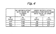
- Fig. 4 shows an example in which the gas recirculation ratio is adjusted by the above-described control procedure.
- the system configuration is as follows.
- the volumetric capacity of the vacuum chamber 1 is 4 L.
- the pumping speed of the first vacuum pump 5 is 1300 L/sec-The pumping speed of the second vacuum pump 7 is 3000 L/min.
- the foreline length i.e. length between an output of the first vacuum pump and an inlet of the second vacuum pump, is 5 m.
- the foreline inner diameter is 40 mm.
- the gas recirculation line length is 1.5 m.
- the gas recirculation line inner diameter is 10 mm.
- the evacuation conditions are as follow.
- the kind of gas used is air.
- the pressure Pc in the vacuum chamber 1 is 50 mTorr (0.05 Torr).
- Fig. 4 shows changes of the pressure Pd in the upstream side of the gas recirculation line 8 (i.e. the pressure detected with the second pressure sensor 12) when the total gas flow rate Qt (Q 1 +Q 2 ) is changed from 250 sccm through 500 sccm to 750 sccm under two different conditions, i.e. one where the gas recirculation line gate valve 9 is closed (no recirculation), and the other where the gas recirculation line gate valve 9 is open (recirculation ratio: 80%).
- the pressure Pd when there is no recirculation changes from 0.26 Torr through 0.36 Torr to 0.45 Torr, whereas the pressure Pd when there is recirculation (recirculation ratio: 80%) changes from 2.5 Torr through 3.8 Torr to 4.7 Torr.
- the present invention provides the following advantageous effects.
- the gas recirculation flow rate Q 2 can be controlled simply by adjusting the differential pressure Pd-Pc in the gas recirculation line by varying the effective pumping speed of the second vacuum pump or the flow rate of the purge gas introduced upstream or inside the second vacuum pump. Therefore, it is possible to provide a gas recirculation flow control method capable of controlling the gas recirculation flow rate (recirculation ratio) as desired irrespective of the magnitude of the differential pressure in the gas recirculation line in a recirculation process in which a part of exhaust gas is returned to the vacuum chamber to increase the utilization efficiency of the unreacted gas.
- the gas recirculation flow control device can control the gas recirculation flow rate Q 2 simply by adjusting the differential pressure Pd-Pc in the gas recirculation line, which is detected with the first and second pressure sensors, by varying the effective pumping speed of the second vacuum pump or the flow rate of the purge gas introduced upstream or inside the second vacuum pump. Therefore, it is possible to provide a gas recirculation flow control apparatus capable of controlling the gas recirculation flow rate (recirculation ratio) as desired irrespective of the magnitude of the differential pressure in the gas recirculation line in a recirculation process in which a part of exhaust gas is returned to the vacuum chamber to increase the utilization efficiency of the unreacted gas.
Landscapes
- Chemical & Material Sciences (AREA)
- General Chemical & Material Sciences (AREA)
- Chemical Kinetics & Catalysis (AREA)
- Engineering & Computer Science (AREA)
- Materials Engineering (AREA)
- Mechanical Engineering (AREA)
- Metallurgy (AREA)
- Organic Chemistry (AREA)
- Chemical Vapour Deposition (AREA)
- Drying Of Semiconductors (AREA)
- Control Of Fluid Pressure (AREA)
- Compressors, Vaccum Pumps And Other Relevant Systems (AREA)
Applications Claiming Priority (2)
| Application Number | Priority Date | Filing Date | Title |
|---|---|---|---|
| JP2001082841 | 2001-03-22 | ||
| JP2001082841A JP4335469B2 (ja) | 2001-03-22 | 2001-03-22 | 真空排気装置のガス循環量調整方法及び装置 |
Publications (2)
| Publication Number | Publication Date |
|---|---|
| EP1243667A2 true EP1243667A2 (fr) | 2002-09-25 |
| EP1243667A3 EP1243667A3 (fr) | 2002-10-02 |
Family
ID=18938736
Family Applications (1)
| Application Number | Title | Priority Date | Filing Date |
|---|---|---|---|
| EP02006584A Withdrawn EP1243667A3 (fr) | 2001-03-22 | 2002-03-21 | Méthode et appareil de controle de flux de recirculation d'un gas pour système de fabrication de semiconducteur sous vide |
Country Status (5)
| Country | Link |
|---|---|
| US (1) | US6782907B2 (fr) |
| EP (1) | EP1243667A3 (fr) |
| JP (1) | JP4335469B2 (fr) |
| KR (1) | KR100877362B1 (fr) |
| TW (1) | TW533504B (fr) |
Cited By (3)
| Publication number | Priority date | Publication date | Assignee | Title |
|---|---|---|---|---|
| FR2863404A1 (fr) * | 2003-12-09 | 2005-06-10 | Cit Alcatel | Dispositif pour la generation et la commande du flux d'agents de nettoyage dans une chambre de procedes |
| WO2010049024A1 (fr) * | 2008-10-31 | 2010-05-06 | Oerlikon Solar Ip Ag, Truebbach | Recyclage de précurseur |
| EP2915901A1 (fr) * | 2014-03-07 | 2015-09-09 | Roth & Rau AG | Dispositif de traitement par plasma avec recirculation de gaz de processus dans de multiples plasmas |
Families Citing this family (64)
| Publication number | Priority date | Publication date | Assignee | Title |
|---|---|---|---|---|
| JP3682207B2 (ja) * | 2000-06-12 | 2005-08-10 | 株式会社東芝 | プラズマ処理方法 |
| US6938638B2 (en) * | 2000-12-28 | 2005-09-06 | Kabushiki Kaisha Toshiba | Gas circulating-processing apparatus |
| WO2002079080A1 (fr) * | 2001-03-29 | 2002-10-10 | Kabushiki Kaisha Toyota Chuo Kenkyusho | Dispositif et procede de production d'une structure a base de silicium |
| GB0214273D0 (en) * | 2002-06-20 | 2002-07-31 | Boc Group Plc | Apparatus for controlling the pressure in a process chamber and method of operating same |
| FR2854667B1 (fr) * | 2003-05-09 | 2006-07-28 | Cit Alcatel | Controle de pression dans la chambre de procedes par variation de vitesse de pompes, vanne de regulation et injection de gaz neutre |
| KR100856317B1 (ko) * | 2003-12-27 | 2008-09-03 | 동부일렉트로닉스 주식회사 | 반도체 제조 설비용 진공 장치 |
| US20050250347A1 (en) * | 2003-12-31 | 2005-11-10 | Bailey Christopher M | Method and apparatus for maintaining by-product volatility in deposition process |
| GB0401396D0 (en) * | 2004-01-22 | 2004-02-25 | Boc Group Plc | Pressure control method |
| JP4633370B2 (ja) * | 2004-02-17 | 2011-02-16 | 財団法人国際科学振興財団 | 真空装置 |
| EP1741802B1 (fr) * | 2004-03-29 | 2013-08-21 | Tadahiro Ohmi | Appareil de formation de film et procede de formation de film |
| FR2878913B1 (fr) * | 2004-12-03 | 2007-01-19 | Cit Alcatel | Controle des pressions partielles de gaz pour optimisation de procede |
| KR20060063188A (ko) * | 2004-12-07 | 2006-06-12 | 삼성전자주식회사 | 화학기상증착장치 및 그를 이용한 화학기상증착방법 |
| US7441439B2 (en) * | 2005-02-07 | 2008-10-28 | Richard Dean Mc Farland | Portable pressure switch calibration and diagnostic tool |
| US20060174686A1 (en) * | 2005-02-07 | 2006-08-10 | Mcfarland Richard D | Portable pressure switch calibration and diagnostic tool |
| WO2006101987A2 (fr) * | 2005-03-17 | 2006-09-28 | Southwest Research Institute | Utilisation de gaz d'echappement recircules dans un systeme de production utilisant un bruleur a des fins de reduction de consommation de carburant et de refroidissement |
| US8282768B1 (en) | 2005-04-26 | 2012-10-09 | Novellus Systems, Inc. | Purging of porogen from UV cure chamber |
| US8454750B1 (en) | 2005-04-26 | 2013-06-04 | Novellus Systems, Inc. | Multi-station sequential curing of dielectric films |
| US8980769B1 (en) | 2005-04-26 | 2015-03-17 | Novellus Systems, Inc. | Multi-station sequential curing of dielectric films |
| US8137465B1 (en) | 2005-04-26 | 2012-03-20 | Novellus Systems, Inc. | Single-chamber sequential curing of semiconductor wafers |
| US8398816B1 (en) * | 2006-03-28 | 2013-03-19 | Novellus Systems, Inc. | Method and apparatuses for reducing porogen accumulation from a UV-cure chamber |
| JP4943047B2 (ja) | 2006-04-07 | 2012-05-30 | 東京エレクトロン株式会社 | 処理装置及び処理方法 |
| US20080072822A1 (en) * | 2006-09-22 | 2008-03-27 | White John M | System and method including a particle trap/filter for recirculating a dilution gas |
| US20080072929A1 (en) * | 2006-09-22 | 2008-03-27 | White John M | Dilution gas recirculation |
| US8235001B2 (en) * | 2007-04-02 | 2012-08-07 | Hitachi Kokusai Electric Inc. | Substrate processing apparatus and method for manufacturing semiconductor device |
| JP2009076881A (ja) * | 2007-08-30 | 2009-04-09 | Tokyo Electron Ltd | 処理ガス供給システム及び処理装置 |
| JP5372353B2 (ja) * | 2007-09-25 | 2013-12-18 | 株式会社フジキン | 半導体製造装置用ガス供給装置 |
| US8426778B1 (en) | 2007-12-10 | 2013-04-23 | Novellus Systems, Inc. | Tunable-illumination reflector optics for UV cure system |
| TW201217756A (en) * | 2010-10-27 | 2012-05-01 | Askey Computer Corp | Air pressure producing apparatus |
| CN102454575A (zh) * | 2010-10-27 | 2012-05-16 | 亚旭电脑股份有限公司 | 空气压力产生装置 |
| JP5582978B2 (ja) * | 2010-11-16 | 2014-09-03 | 日立造船株式会社 | 反応室のガス排出装置 |
| KR101427726B1 (ko) * | 2011-12-27 | 2014-08-07 | 가부시키가이샤 히다치 고쿠사이 덴키 | 기판 처리 장치 및 반도체 장치의 제조 방법 |
| GB2499217A (en) * | 2012-02-08 | 2013-08-14 | Edwards Ltd | Vacuum pump with recirculation valve |
| GB2501735B (en) * | 2012-05-02 | 2015-07-22 | Edwards Ltd | Method and apparatus for warming up a vacuum pump arrangement |
| US9490149B2 (en) * | 2013-07-03 | 2016-11-08 | Lam Research Corporation | Chemical deposition apparatus having conductance control |
| US9028765B2 (en) | 2013-08-23 | 2015-05-12 | Lam Research Corporation | Exhaust flow spreading baffle-riser to optimize remote plasma window clean |
| US10443127B2 (en) * | 2013-11-05 | 2019-10-15 | Taiwan Semiconductor Manufacturing Company Limited | System and method for supplying a precursor for an atomic layer deposition (ALD) process |
| DE102013223556A1 (de) * | 2013-11-19 | 2015-05-21 | Oerlikon Leybold Vacuum Gmbh | Vakuumpumpen-System sowie Verfahren zum Betreiben eines Vakuumpumpen-Systems |
| US9640344B2 (en) * | 2014-02-07 | 2017-05-02 | Good Day Tools Llc | Portable pressure switch calibration and diagnostic tool |
| CN104979227B (zh) * | 2014-04-02 | 2018-03-30 | 中芯国际集成电路制造(上海)有限公司 | 半导体数据收集方法及系统 |
| US10388546B2 (en) | 2015-11-16 | 2019-08-20 | Lam Research Corporation | Apparatus for UV flowable dielectric |
| JP2018013109A (ja) * | 2016-07-22 | 2018-01-25 | 株式会社島津製作所 | 排気システムおよび制御装置 |
| US10224224B2 (en) | 2017-03-10 | 2019-03-05 | Micromaterials, LLC | High pressure wafer processing systems and related methods |
| US10847360B2 (en) | 2017-05-25 | 2020-11-24 | Applied Materials, Inc. | High pressure treatment of silicon nitride film |
| US10622214B2 (en) | 2017-05-25 | 2020-04-14 | Applied Materials, Inc. | Tungsten defluorination by high pressure treatment |
| US10276411B2 (en) | 2017-08-18 | 2019-04-30 | Applied Materials, Inc. | High pressure and high temperature anneal chamber |
| JP6947914B2 (ja) | 2017-08-18 | 2021-10-13 | アプライド マテリアルズ インコーポレイテッドApplied Materials,Incorporated | 高圧高温下のアニールチャンバ |
| CN111095524B (zh) | 2017-09-12 | 2023-10-03 | 应用材料公司 | 用于使用保护阻挡物层制造半导体结构的设备和方法 |
| KR102585074B1 (ko) | 2017-11-11 | 2023-10-04 | 마이크로머티어리얼즈 엘엘씨 | 고압 프로세싱 챔버를 위한 가스 전달 시스템 |
| SG11202003438QA (en) | 2017-11-16 | 2020-05-28 | Applied Materials Inc | High pressure steam anneal processing apparatus |
| JP2021503714A (ja) | 2017-11-17 | 2021-02-12 | アプライド マテリアルズ インコーポレイテッドApplied Materials,Incorporated | 高圧処理システムのためのコンデンサシステム |
| JP7299898B2 (ja) | 2018-01-24 | 2023-06-28 | アプライド マテリアルズ インコーポレイテッド | 高圧アニールを用いたシーム修復 |
| CN111902929B (zh) | 2018-03-09 | 2025-09-19 | 应用材料公司 | 用于含金属材料的高压退火处理 |
| US10714331B2 (en) | 2018-04-04 | 2020-07-14 | Applied Materials, Inc. | Method to fabricate thermally stable low K-FinFET spacer |
| US10950429B2 (en) | 2018-05-08 | 2021-03-16 | Applied Materials, Inc. | Methods of forming amorphous carbon hard mask layers and hard mask layers formed therefrom |
| US10704141B2 (en) | 2018-06-01 | 2020-07-07 | Applied Materials, Inc. | In-situ CVD and ALD coating of chamber to control metal contamination |
| US10748783B2 (en) | 2018-07-25 | 2020-08-18 | Applied Materials, Inc. | Gas delivery module |
| US10675581B2 (en) | 2018-08-06 | 2020-06-09 | Applied Materials, Inc. | Gas abatement apparatus |
| JP7179172B6 (ja) | 2018-10-30 | 2022-12-16 | アプライド マテリアルズ インコーポレイテッド | 半導体用途の構造体をエッチングするための方法 |
| KR20210077779A (ko) | 2018-11-16 | 2021-06-25 | 어플라이드 머티어리얼스, 인코포레이티드 | 강화된 확산 프로세스를 사용한 막 증착 |
| WO2020117462A1 (fr) | 2018-12-07 | 2020-06-11 | Applied Materials, Inc. | Système de traitement de semi-conducteurs |
| US11901222B2 (en) | 2020-02-17 | 2024-02-13 | Applied Materials, Inc. | Multi-step process for flowable gap-fill film |
| CN111370286B (zh) * | 2020-03-24 | 2023-02-07 | 中国科学院近代物理研究所 | 一种用于治疗装备的等离子体源及其使用方法 |
| US12191214B2 (en) * | 2021-03-05 | 2025-01-07 | Taiwan Semiconductor Manufacturing Company Limited | System and methods for controlling an amount of primer in a primer application gas |
| KR102794198B1 (ko) * | 2022-11-30 | 2025-04-11 | 세메스 주식회사 | 픽업 장치 및 픽업 방법 |
Citations (2)
| Publication number | Priority date | Publication date | Assignee | Title |
|---|---|---|---|---|
| US4728869A (en) | 1985-12-18 | 1988-03-01 | Anicon, Inc. | Pulsewidth modulated pressure control system for chemical vapor deposition apparatus |
| JPH10125657A (ja) | 1996-10-16 | 1998-05-15 | Ebara Corp | 真空排気装置 |
Family Cites Families (13)
| Publication number | Priority date | Publication date | Assignee | Title |
|---|---|---|---|---|
| US3537474A (en) * | 1968-02-19 | 1970-11-03 | Varian Associates | Push button vacuum control valve and vacuum system using same |
| JPS5964516A (ja) | 1982-10-01 | 1984-04-12 | Fuji Electric Corp Res & Dev Ltd | アモルフアスシリコン膜生成方法 |
| DE3605172A1 (de) * | 1986-02-19 | 1987-08-20 | Sueddeutsche Kalkstickstoff | Verfahren zur regelung des kontinuierlichen abzugs von gasen aus geschlossenen reaktoren |
| US4699570A (en) * | 1986-03-07 | 1987-10-13 | Itt Industries, Inc | Vacuum pump system |
| US5433238A (en) * | 1992-12-18 | 1995-07-18 | Vlsi Technology, Inc. | Pumping system for evacuating reactor chambers |
| JP3595823B2 (ja) | 1994-07-28 | 2004-12-02 | 有限会社 渕田ナノ技研 | 金属部分膜の形成装置およびその形成方法 |
| JPH09251981A (ja) | 1996-03-14 | 1997-09-22 | Toshiba Corp | 半導体製造装置 |
| JPH10122178A (ja) * | 1996-10-16 | 1998-05-12 | Ebara Corp | 真空ポンプ及びそのパージ方法 |
| US5944049A (en) * | 1997-07-15 | 1999-08-31 | Applied Materials, Inc. | Apparatus and method for regulating a pressure in a chamber |
| GB9717400D0 (en) * | 1997-08-15 | 1997-10-22 | Boc Group Plc | Vacuum pumping systems |
| JP4112659B2 (ja) | 1997-12-01 | 2008-07-02 | 大陽日酸株式会社 | 希ガスの回収方法及び装置 |
| DE19929519A1 (de) * | 1999-06-28 | 2001-01-04 | Pfeiffer Vacuum Gmbh | Verfahren zum Betrieb einer Mehrkammer-Vakuumanlage |
| JP3682207B2 (ja) | 2000-06-12 | 2005-08-10 | 株式会社東芝 | プラズマ処理方法 |
-
2001
- 2001-03-22 JP JP2001082841A patent/JP4335469B2/ja not_active Expired - Fee Related
-
2002
- 2002-03-21 EP EP02006584A patent/EP1243667A3/fr not_active Withdrawn
- 2002-03-21 US US10/101,923 patent/US6782907B2/en not_active Expired - Fee Related
- 2002-03-22 KR KR1020020015671A patent/KR100877362B1/ko not_active Expired - Fee Related
- 2002-03-22 TW TW091105530A patent/TW533504B/zh not_active IP Right Cessation
Patent Citations (2)
| Publication number | Priority date | Publication date | Assignee | Title |
|---|---|---|---|---|
| US4728869A (en) | 1985-12-18 | 1988-03-01 | Anicon, Inc. | Pulsewidth modulated pressure control system for chemical vapor deposition apparatus |
| JPH10125657A (ja) | 1996-10-16 | 1998-05-15 | Ebara Corp | 真空排気装置 |
Non-Patent Citations (1)
| Title |
|---|
| PATENT ABSTRACTS OF JAPAN, no. 10, 31 August 1998 (1998-08-31) |
Cited By (5)
| Publication number | Priority date | Publication date | Assignee | Title |
|---|---|---|---|---|
| FR2863404A1 (fr) * | 2003-12-09 | 2005-06-10 | Cit Alcatel | Dispositif pour la generation et la commande du flux d'agents de nettoyage dans une chambre de procedes |
| EP1541709A1 (fr) * | 2003-12-09 | 2005-06-15 | Alcatel | Arrangement pour le contrôle du flux d'agents de nettoyage dans un dispositif de recirculation |
| WO2010049024A1 (fr) * | 2008-10-31 | 2010-05-06 | Oerlikon Solar Ip Ag, Truebbach | Recyclage de précurseur |
| EP2915901A1 (fr) * | 2014-03-07 | 2015-09-09 | Roth & Rau AG | Dispositif de traitement par plasma avec recirculation de gaz de processus dans de multiples plasmas |
| WO2015132214A1 (fr) * | 2014-03-07 | 2015-09-11 | Roth & Rau Ag | Dispositif de traitement au plasma à circulation de gaz de traitement dans de multiples plasmas |
Also Published As
| Publication number | Publication date |
|---|---|
| JP4335469B2 (ja) | 2009-09-30 |
| TW533504B (en) | 2003-05-21 |
| US20020134439A1 (en) | 2002-09-26 |
| KR20020075296A (ko) | 2002-10-04 |
| KR100877362B1 (ko) | 2009-01-07 |
| JP2002273198A (ja) | 2002-09-24 |
| EP1243667A3 (fr) | 2002-10-02 |
| US6782907B2 (en) | 2004-08-31 |
Similar Documents
| Publication | Publication Date | Title |
|---|---|---|
| EP1243667A2 (fr) | Méthode et appareil de controle de flux de recirculation d'un gas pour système de fabrication de semiconducteur sous vide | |
| US11345999B2 (en) | Method of using a gas-phase reactor system including analyzing exhausted gas | |
| US6074202A (en) | Apparatus for manufacturing a semiconductor material | |
| JP3486821B2 (ja) | 処理装置及び処理装置内の被処理体の搬送方法 | |
| JP2009521595A (ja) | 前置ポンプの反応性気体噴射システムへの反応性気体の供給量を監視し且つ制御するための分光計測技術の使用 | |
| JP2009511248A (ja) | ターボポンプを使用する広範囲圧力制御 | |
| JP2001060578A (ja) | 真空処理装置 | |
| US20080311731A1 (en) | Low pressure chemical vapor deposition of polysilicon on a wafer | |
| US6139640A (en) | Chemical vapor deposition system and method employing a mass flow controller | |
| JPH09189290A (ja) | 真空処理装置 | |
| US20090112370A1 (en) | Vacuum system and method for operating the same | |
| JP2008248395A (ja) | プラズマ処理装置およびプラズマ処理装置の調圧方法 | |
| JP2006319207A (ja) | 流量制御装置、薄膜堆積装置および流量制御方法 | |
| JP2001060555A (ja) | 基板処理方法 | |
| KR100808372B1 (ko) | 화학기상증착장치의 진공 시스템 및 이의 제어 방법 | |
| KR101862806B1 (ko) | 원자층 증착 장치의 배기 시스템 | |
| JP2002110560A (ja) | 半導体製造装置 | |
| JPH0679159A (ja) | 真空室用ガス導入装置 | |
| JP3037173B2 (ja) | 減圧処理装置 | |
| KR20010048976A (ko) | 반도체 에이.피.씨.브이.디. 및 에피텍셜 공정용반응챔버의 가스배기시스템 | |
| KR200249178Y1 (ko) | 유량계를 이용한 챔버 압력 제어장치 | |
| JP2002343792A (ja) | 膜形成方法及び装置 | |
| JPH01183112A (ja) | スパッタ蒸着装置 | |
| JP2003131743A (ja) | 排気装置の圧力制御システム | |
| KR200267582Y1 (ko) | Lpcvd 장치의 진공공급 시스템 |
Legal Events
| Date | Code | Title | Description |
|---|---|---|---|
| PUAI | Public reference made under article 153(3) epc to a published international application that has entered the european phase |
Free format text: ORIGINAL CODE: 0009012 |
|
| PUAL | Search report despatched |
Free format text: ORIGINAL CODE: 0009013 |
|
| AK | Designated contracting states |
Kind code of ref document: A2 Designated state(s): AT BE CH CY DE DK ES FI FR GB GR IE IT LI LU MC NL PT SE TR |
|
| AX | Request for extension of the european patent |
Free format text: AL;LT;LV;MK;RO;SI |
|
| AK | Designated contracting states |
Kind code of ref document: A3 Designated state(s): AT BE CH CY DE DK ES FI FR GB GR IE IT LI LU MC NL PT SE TR |
|
| AX | Request for extension of the european patent |
Free format text: AL;LT;LV;MK;RO;SI |
|
| RIC1 | Information provided on ipc code assigned before grant |
Free format text: 7C 23C 16/50 A, 7H 01L 21/00 B, 7C 23C 16/455 B, 7C 23C 16/44 B |
|
| 17P | Request for examination filed |
Effective date: 20030327 |
|
| AKX | Designation fees paid |
Designated state(s): DE FR GB |
|
| 17Q | First examination report despatched |
Effective date: 20091027 |
|
| STAA | Information on the status of an ep patent application or granted ep patent |
Free format text: STATUS: THE APPLICATION IS DEEMED TO BE WITHDRAWN |
|
| 18D | Application deemed to be withdrawn |
Effective date: 20141001 |