EP1741802B1 - Appareil de formation de film et procede de formation de film - Google Patents
Appareil de formation de film et procede de formation de film Download PDFInfo
- Publication number
- EP1741802B1 EP1741802B1 EP05727877.2A EP05727877A EP1741802B1 EP 1741802 B1 EP1741802 B1 EP 1741802B1 EP 05727877 A EP05727877 A EP 05727877A EP 1741802 B1 EP1741802 B1 EP 1741802B1
- Authority
- EP
- European Patent Office
- Prior art keywords
- film
- forming
- temperature
- gas
- substrate
- Prior art date
- Legal status (The legal status is an assumption and is not a legal conclusion. Google has not performed a legal analysis and makes no representation as to the accuracy of the status listed.)
- Expired - Lifetime
Links
- 0 C*CC=CC1C=*C=C1 Chemical compound C*CC=CC1C=*C=C1 0.000 description 2
Images











Classifications
-
- C—CHEMISTRY; METALLURGY
- C23—COATING METALLIC MATERIAL; COATING MATERIAL WITH METALLIC MATERIAL; CHEMICAL SURFACE TREATMENT; DIFFUSION TREATMENT OF METALLIC MATERIAL; COATING BY VACUUM EVAPORATION, BY SPUTTERING, BY ION IMPLANTATION OR BY CHEMICAL VAPOUR DEPOSITION, IN GENERAL; INHIBITING CORROSION OF METALLIC MATERIAL OR INCRUSTATION IN GENERAL
- C23C—COATING METALLIC MATERIAL; COATING MATERIAL WITH METALLIC MATERIAL; SURFACE TREATMENT OF METALLIC MATERIAL BY DIFFUSION INTO THE SURFACE, BY CHEMICAL CONVERSION OR SUBSTITUTION; COATING BY VACUUM EVAPORATION, BY SPUTTERING, BY ION IMPLANTATION OR BY CHEMICAL VAPOUR DEPOSITION, IN GENERAL
- C23C14/00—Coating by vacuum evaporation, by sputtering or by ion implantation of the coating forming material
- C23C14/22—Coating by vacuum evaporation, by sputtering or by ion implantation of the coating forming material characterised by the process of coating
- C23C14/24—Vacuum evaporation
- C23C14/243—Crucibles for source material
-
- C—CHEMISTRY; METALLURGY
- C23—COATING METALLIC MATERIAL; COATING MATERIAL WITH METALLIC MATERIAL; CHEMICAL SURFACE TREATMENT; DIFFUSION TREATMENT OF METALLIC MATERIAL; COATING BY VACUUM EVAPORATION, BY SPUTTERING, BY ION IMPLANTATION OR BY CHEMICAL VAPOUR DEPOSITION, IN GENERAL; INHIBITING CORROSION OF METALLIC MATERIAL OR INCRUSTATION IN GENERAL
- C23C—COATING METALLIC MATERIAL; COATING MATERIAL WITH METALLIC MATERIAL; SURFACE TREATMENT OF METALLIC MATERIAL BY DIFFUSION INTO THE SURFACE, BY CHEMICAL CONVERSION OR SUBSTITUTION; COATING BY VACUUM EVAPORATION, BY SPUTTERING, BY ION IMPLANTATION OR BY CHEMICAL VAPOUR DEPOSITION, IN GENERAL
- C23C14/00—Coating by vacuum evaporation, by sputtering or by ion implantation of the coating forming material
- C23C14/22—Coating by vacuum evaporation, by sputtering or by ion implantation of the coating forming material characterised by the process of coating
- C23C14/54—Controlling or regulating the coating process
- C23C14/541—Heating or cooling of the substrates
-
- C—CHEMISTRY; METALLURGY
- C23—COATING METALLIC MATERIAL; COATING MATERIAL WITH METALLIC MATERIAL; CHEMICAL SURFACE TREATMENT; DIFFUSION TREATMENT OF METALLIC MATERIAL; COATING BY VACUUM EVAPORATION, BY SPUTTERING, BY ION IMPLANTATION OR BY CHEMICAL VAPOUR DEPOSITION, IN GENERAL; INHIBITING CORROSION OF METALLIC MATERIAL OR INCRUSTATION IN GENERAL
- C23C—COATING METALLIC MATERIAL; COATING MATERIAL WITH METALLIC MATERIAL; SURFACE TREATMENT OF METALLIC MATERIAL BY DIFFUSION INTO THE SURFACE, BY CHEMICAL CONVERSION OR SUBSTITUTION; COATING BY VACUUM EVAPORATION, BY SPUTTERING, BY ION IMPLANTATION OR BY CHEMICAL VAPOUR DEPOSITION, IN GENERAL
- C23C14/00—Coating by vacuum evaporation, by sputtering or by ion implantation of the coating forming material
- C23C14/06—Coating by vacuum evaporation, by sputtering or by ion implantation of the coating forming material characterised by the coating material
- C23C14/12—Organic material
-
- C—CHEMISTRY; METALLURGY
- C23—COATING METALLIC MATERIAL; COATING MATERIAL WITH METALLIC MATERIAL; CHEMICAL SURFACE TREATMENT; DIFFUSION TREATMENT OF METALLIC MATERIAL; COATING BY VACUUM EVAPORATION, BY SPUTTERING, BY ION IMPLANTATION OR BY CHEMICAL VAPOUR DEPOSITION, IN GENERAL; INHIBITING CORROSION OF METALLIC MATERIAL OR INCRUSTATION IN GENERAL
- C23C—COATING METALLIC MATERIAL; COATING MATERIAL WITH METALLIC MATERIAL; SURFACE TREATMENT OF METALLIC MATERIAL BY DIFFUSION INTO THE SURFACE, BY CHEMICAL CONVERSION OR SUBSTITUTION; COATING BY VACUUM EVAPORATION, BY SPUTTERING, BY ION IMPLANTATION OR BY CHEMICAL VAPOUR DEPOSITION, IN GENERAL
- C23C14/00—Coating by vacuum evaporation, by sputtering or by ion implantation of the coating forming material
- C23C14/22—Coating by vacuum evaporation, by sputtering or by ion implantation of the coating forming material characterised by the process of coating
- C23C14/228—Gas flow assisted PVD deposition
-
- C—CHEMISTRY; METALLURGY
- C23—COATING METALLIC MATERIAL; COATING MATERIAL WITH METALLIC MATERIAL; CHEMICAL SURFACE TREATMENT; DIFFUSION TREATMENT OF METALLIC MATERIAL; COATING BY VACUUM EVAPORATION, BY SPUTTERING, BY ION IMPLANTATION OR BY CHEMICAL VAPOUR DEPOSITION, IN GENERAL; INHIBITING CORROSION OF METALLIC MATERIAL OR INCRUSTATION IN GENERAL
- C23C—COATING METALLIC MATERIAL; COATING MATERIAL WITH METALLIC MATERIAL; SURFACE TREATMENT OF METALLIC MATERIAL BY DIFFUSION INTO THE SURFACE, BY CHEMICAL CONVERSION OR SUBSTITUTION; COATING BY VACUUM EVAPORATION, BY SPUTTERING, BY ION IMPLANTATION OR BY CHEMICAL VAPOUR DEPOSITION, IN GENERAL
- C23C14/00—Coating by vacuum evaporation, by sputtering or by ion implantation of the coating forming material
- C23C14/22—Coating by vacuum evaporation, by sputtering or by ion implantation of the coating forming material characterised by the process of coating
- C23C14/56—Apparatus specially adapted for continuous coating; Arrangements for maintaining the vacuum, e.g. vacuum locks
- C23C14/564—Means for minimising impurities in the coating chamber such as dust, moisture, residual gases
-
- F—MECHANICAL ENGINEERING; LIGHTING; HEATING; WEAPONS; BLASTING
- F28—HEAT EXCHANGE IN GENERAL
- F28F—DETAILS OF HEAT-EXCHANGE AND HEAT-TRANSFER APPARATUS, OF GENERAL APPLICATION
- F28F13/00—Arrangements for modifying heat-transfer, e.g. increasing, decreasing
- F28F13/06—Arrangements for modifying heat-transfer, e.g. increasing, decreasing by affecting the pattern of flow of the heat-exchange media
- F28F13/08—Arrangements for modifying heat-transfer, e.g. increasing, decreasing by affecting the pattern of flow of the heat-exchange media by varying the cross-section of the flow channels
-
- F—MECHANICAL ENGINEERING; LIGHTING; HEATING; WEAPONS; BLASTING
- F28—HEAT EXCHANGE IN GENERAL
- F28D—HEAT-EXCHANGE APPARATUS, NOT PROVIDED FOR IN ANOTHER SUBCLASS, IN WHICH THE HEAT-EXCHANGE MEDIA DO NOT COME INTO DIRECT CONTACT
- F28D21/00—Heat-exchange apparatus not covered by any of the groups F28D1/00 - F28D20/00
- F28D2021/0019—Other heat exchangers for particular applications; Heat exchange systems not otherwise provided for
- F28D2021/0077—Other heat exchangers for particular applications; Heat exchange systems not otherwise provided for for tempering, e.g. with cooling or heating circuits for temperature control of elements
-
- F—MECHANICAL ENGINEERING; LIGHTING; HEATING; WEAPONS; BLASTING
- F28—HEAT EXCHANGE IN GENERAL
- F28F—DETAILS OF HEAT-EXCHANGE AND HEAT-TRANSFER APPARATUS, OF GENERAL APPLICATION
- F28F9/00—Casings; Header boxes; Auxiliary supports for elements; Auxiliary members within casings
- F28F9/02—Header boxes; End plates
- F28F9/026—Header boxes; End plates with static flow control means, e.g. with means for uniformly distributing heat exchange media into conduits
Definitions
- This invention relates to a film-forming apparatus and a film-forming method for forming a film layer of a predetermined material and, in particular, relates to a film-forming apparatus and a film-forming method for forming a film layer of a predetermined material by evaporating a raw material of the predetermined material.
- Organic EL display device with sufficiently high brightness and a lifetime of several tens of thousands of hours or more uses an organic EL element that is a self-luminous element and thus can be formed thin with less peripheral components such as a backlight. Therefore, the organic EL display device is ideal as a flat panel display device.
- the organic EL element forming such an organic EL display device is required, in terms of characteristics as the display device, such that, while being a large screen, the element lifetime is long, there are no variations in luminous brightness on the screen and in element lifetime, there are no defects typified by dark spots, and so on. Film formation of an organic EL layer is quite important for satisfying those requirements.
- Patent Document 1 As a film-forming apparatus for uniformly forming a film of an organic EL layer on a large substrate, use is comprised of an apparatus described in Patent Document 1 or the like.
- the film-forming apparatus of Patent Document 1 is intended to ensure uniformity of the film thickness on a large substrate by optimally arranging in a tree fashion the piping structure inside an injector located in the apparatus.
- An organic EL layer currently is formed by a vacuum deposition apparatus at 10 -6 Torr to 10 -7 Torr or less. According to an experiment by the inventors, it has been clarified that, in a current organic EL vacuum deposition apparatus, an organic EL layer is subjected to a large amount of organic contamination in an organic EL layer forming process, so that the brightness and lifetime of an organic EL light emitting diode (OLED) are largely reduced.
- Fig. 1 shows a sectional structure of a green light emitting OLED used in the experiment.
- a glass substrate 101 has a thickness of 0.3 to 1.0mm
- an ITO transparent electrode 102 (work function -4.80eV) has a thickness of 100 to 150mm
- an ITO layer 103 has a thickness of 5 to 10mm and a work function controlled to approximately -5.2eV by adding V (vanadium) to approximately several percents
- a hole transport layer (NPD) 104 has a thickness of approximately 40nm
- a light emitting layer (Alq3) 105 has a thickness of approximately 40nm
- an electron injection cathode electrode (MgAg) 106 (work function -3.7eV) likewise has a thickness of approximately 40nm
- a metal electrode (Ag) 107 has a thickness of approximately 100nm
- a SiO 2 protective film 108 has a thickness of 3 to 5 ⁇ m and is adapted to prevent invasion of moisture and so on from the atmosphere.
- the emission wavelength is approximately 520nm.
- the ITO transparent electrodes 102 and 103 were sputter-deposited at a temperature of approximately 250°C and then annealed in a N 2 gas atmosphere at 300°C.
- the NPD 104 and Alq3 105 of organic EL films were formed by deposition in a vacuum of approximately 1 x 10 -7 Torr.
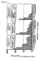
- a graph of black circles in Fig. 2 shows results of forming films of the NPD layer, the Alq3 layer, and the MgAg electrode layer immediately after transfer of the glass substrate in a continuous vacuum deposition apparatus of a shape provided with a load lock chamber (assuming that the load lock chamber is also set in a vacuum of approximately 1 x 10 -7 Torr).
- a graph of black triangles in Fig. 2 shows results of leaving the substrate standing in an atmosphere of approximately 1 x 10 -7 Torr for 30 minutes when film formation of the respective layers.
- the current value was 15mA/cm 2 .
- the brightness of the sample exposed to the atmosphere of approximately 1 x 10 -7 Torr, for 30 minutes at the time of the film formation of the respective layers was changed to approximately 1/3 and the lifetime in which the brightness was degraded to half was reduced to 1/3 or less.
- Patent Document 1 Japanese Unexamined Patent Application Publication JP-2004-79904-A2 JP 2005-58978 A (and corresponding document US 2006/0278162 A1 ) discloses a film-forming apparatus usable for manufacture of an organic EL element and comprising a crucible formed from a material having low catalytic activity such as aluminium oxide, aluminium nitride, yttrium oxide and magnesium oxide.
- a vacuum deposition apparatus containing a graphite boat for evaporating organic material is disclosed in JP 11-189862 A .
- the conventional film-forming method has a problem that since, basically, the raw material is evaporated from an evaporation dish and adhered to the substrate without directionality (i.e. with non-directionality), the film formation takes time and further it is difficult to form a uniform film. This problem is more serious for film formation on a substrate with an increased area, which is one of the industrial features in recent years. For example, approximately 4 minutes are required for forming a single-color organic EL layer on a glass substrate having a size of 400mm x 500mm, because, since it is composed of a hole injection layer, a hole transport layer, a light emitting layer, an electron injection layer, and so on, it is necessary to carry out film formation of as many as several organic compound layers. Further, as long as approximately 20 minutes are required for completing formation of a three-color organic EL layer including times for transfer, mask changes, and so on, thereby an increase in cost has been caused.
- the conventional film-forming method has a problem that since the evaporated raw material is dispersed without directionality, it is also adhered to portions other than the substrate and hence there is much waste. There is also a problem that since the evaporation continues for some time even after heating of the evaporation dish is stopped, a waste of the raw material occurs during non-film formation. For example, since the organic EL film-forming raw material is expensive, these problems are even more serious.
- an object of this invention is to provide a film-forming apparatus and a film-forming method that can increase the film-forming rate and enable uniform film formation by directing an evaporated raw material toward a substrate.
- Another object of this invention is to provide a film-forming apparatus and a film-forming method that are highly economical with a waste of raw material eliminated.
- Another object of this invention is to provide a film-forming apparatus and a film-forming method that can carry out film formation on a large-area substrate at a high rate and highly economically.
- Still another object of this invention is to provide a film-forming apparatus and a film-forming method with suppressed organic compound contamination.
- the film-forming conditions can be controlled by the flow of the gas and hence a uniform thin film can be deposited on the large-area substrate. That is, by directing the evaporated raw material toward the substrate, it is possible to increase the film-forming rate and achieve uniform ilm formation. For example, approximately one to two minutes are enough for forming a three-color organic EL layer on a glass substrate having a size of 400mm x 500mm and hence the film-forming time can be shorted to 1/10 or less as compared with conventional.
- the expensive raw material can be selectively adhered only on the substrate, thereby enabling highly economical film formation with a waste of the raw material eliminated. Further, since use is comprised of the method that transfers the evaporated film-forming material on the flow of the transport gas, it is possible to stop ejection of the raw material by stopping the flow of the gas during non-film formation and hence it is possible to prevent generation of waste of the raw material.
- the film-forming apparatus of this invention thoroughly eliminates generation of the organic compound contamination substance/material decomposition dissociation substance that adversely affects the properties of the film-forming material, and thus can deposit a high-quality thin film.
- the film-forming apparatus of this invention for forming an organic EL element, it is possible to obtain a high-quality organic EL display device with high brightness and long lifetime.
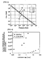
- Fig. 3 shows the gas pressure dependence of the mean free paths of Ar (mass number 40), Kr (mass number 80), and Xe (mass number 131) being typical gases.
- the mean free path increases in inverse proportion to the pressure and decreases when gas atoms/molecules increase in weight or the collision cross section increases.
- the mean free path normally reaches several hundred meters at 1 x 10 -7 Torr. It is well known that when the surface of a substrate is exposed to air in a clean room, a large amount of organic compound is adsorbed thereon.
- Fig. 4 shows the time dependence of organic compound adsorption on the surfaces of thermal oxide film (SiO 2 ) coated silicon substrates when the substrates were exposed in a clean room at room temperature T and in a substrate transfer chamber is depressurized to 1 mTorr or less.
- the organic compound adsorbed on the substrate surfaces was measured by a thermal desorption gas chromatograph/mass spectral method.
- the organic compound adsorption amount is indicated in terms of straight-chain hydrocarbon hexadecane (C 16 H 34 ,CH 3 (CH 2 ) 14 CH 3 : molecular weight 226).
- Fig 4 shows that the adsorption amount of organic compound is much greater under vacuum reduced pressure which has been considered a clean atmosphere.
- origins of such organic compound are components adsorbed on the inner surfaces of the chamber from the atmosphere when the inside of the chamber is exposed to the atmosphere, evaporation of grease or the like applied to mechanical sliding portions for substrate transfer or the like, evaporation from plastic O-rings for maintaining the atmospheric vacuum reduced pressure, back diffusion, to the chamber, of evaporated components of grease on the secondary side of a gas exhaust pump coupled for vacuum evacuation, and so on.
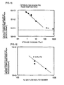
- Fig. 5 shows the storage pressure dependence of surface-adsorbed organic compound amounts when thermal oxide film coated silicon substrates treated with a 0.5% HF solution for 5 minutes and rinsed with ultrapure water for 20 minutes were exposed to atmospheres of 0.8 Torr to 10 Torr at room temperature for 60 minutes.
- the storage pressure was controlled by setting the N 2 gas flow rate constant at 300cc/min and changing the pumping speed of an exhaust pump.
- Fig. 6 shows measurement results of adsorption organic compound amounts on the surfaces of substrates when the gas flow rate to a chamber was increased to 500cc/min from 300cc/min while fixing the storage pressure at 3 Torr in the same experiment. The results of Fig. 6 show that the adsorption organic compound amount decreases in inverse proportion to the increase in gas flow rate even under the same storage pressure.
- Fig. 7 shows the time dependence of organic compound amount adsorbed on the surface of a thermal oxide film coated silicon substrate left standing at a vacuum pressure of 7.5 x 10 -8 Torr (gas flow rate : zero).
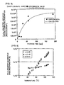
- Fig. 8 shows ion currents of mass numbers 28, 43, and 57 measured by a quadrupole mass spectrometer when the temperature is changed in the state where a thermal oxide film coated silicon substrate adhered with eicosane (C 20 H 42 :CH 3 (CH 2 ) 18 CH 3 : molecular weight 282, vapor pressure at 25°C : 9.1 x 10 -5 mmHg, melting point 36°C, boiling point 237 to 240°C) being straight-chain hydrocarbon is located in a chamber maintained at 7.5 x 10 -8 Torr.
- eicosane C 20 H 42 :CH 3 (CH 2 ) 18 CH 3 : molecular weight 282
- the ion current of mass number 28 represents N 2 molecules being the residue of the atmosphere, while the ion currents of mass numbers 43 and 57 represent ion currents of dissociated components of the eicosane (C 20 H 42 : molecular weight 282). Although the N 2 molecule ion current hardly depends on the temperature, the C 20 H 42 ion currents increase exponential-functionally along with the temperature rise.
- Fig. 9 shows the pressure dependence of ion voltages of mass numbers 28, 43, and 57 likewise by the quadrupole mass spectrometer when the pressure in the chamber is changed from 7.5 x 10 -8 Torr to 3 x 10 -6 Torr by a N 2 gas while maintaining the temperature constant.
- Fig. 9 shows that even if the pressure (total pressure) in the chamber is changed by approximately two digits, the pressure of C 20 H 42 does not change at all. That is, it has been confirmed that the vapor pressure of organic compound molecules (C 20 H 42 in this case) depends only on the temperature and does not depend on the pressure.
- Fig. 10 shows the results of replotting the results of C 20 H 42 in Fig. 8 so as to match the Antonie equation.
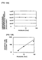
- Fig. 11 shows the results of inserting SiO 2 coated silicon substrates with clean surfaces in the same chamber and examining the atmospheric pressure dependence of C 20 H 42 molecule adsorption onto the clean silicon substrate surfaces.
- Fig. 11 there is shown the exposure time dependence of the numbers of C 20 H 42 molecules adsorbed on the clean SiO 2 coated silicon substrates when the pressure in the chamber is changed to three kinds, i.e. 90 Torr, 10 Torr, and 3 Torr. It is clear from Fig. 11 that the surface equilibrium adsorption amount hardly changes even if the pressure in the chamber changes and that the adsorption time constant decreases along with the pressure drop.
- Fig. 13 shows the atmospheric pressure dependence of substrate surface adsorption amounts of C 20 H 42 molecules when the exposure time of the surfaces of substrates is changed to seven kinds from 1 minute to 400 minutes.
- the technique has become obvious that thoroughly suppresses organic compound molecule adsorption onto the substrate surface for ultrahigh-quality process management.
- Figs. 14A to 14C show the results of examining adsorption amounts on the surfaces of substrates at room temperature under the atmospheric pressure by changing the molecular weights of straight-chain hydrocarbon (C n H 2n+2 ), phthalate ester, and cyclic siloxane, respectively
- organic compound molecule having a small molecular weight is not adsorbed on the surface of the substrate because its adsorption/desorption activation energy is small. Since the organic compound molecule having a molecular weight greater than a certain value (approximately 400 in the case of straight-chain hydrocarbon or phthalate ester and approximately 900 in the case of cyclic siloxane) is not released into the gas phase because its vapor pressure is small, it is not adsorbed on the substrate. Naturally, as the temperature rises, the critical molecular weight of organic compound released into the gas phase shifts to the greater side more and more.
- a certain value approximately 400 in the case of straight-chain hydrocarbon or phthalate ester and approximately 900 in the case of cyclic siloxane
- Use should be comprised of an O-ring of a resin that contains no low-molecular-weight organic compound that is released into the gas phase and adsorbed on the substrate surface (e.g. DU351 manufactured by Daikin Industries, Ltd.). With respect also to the grease in item (b), use should be comprised of one that contains no low-molecular-weight organic compound that is released into the gas phase.
- organic compound having a molecular weight of 800 or less is not contained in the case of straight-chain hydrocarbon or phthalate ester, organic compound having a molecular weight of 1500 or less is not contained in the case of cyclic siloxane, and so on.
- Fig. 15 shows a pump system coupled to a chamber 6 of an organic film-forming apparatus.
- valves 1 to 5 there are included valves 1 to 5, the chamber 6, a turbo-molecular pump 7, a purge port 8, a roughing vacuum pump 9, and an exhaust duct 10.
- the high-vacuum evacuation turbo-molecular pump 7 (pumping speed S 1 (litter/sec)) is coupled to the chamber 6 through the gate valve 1 (butterfly valve or the like) and is coupled to the roughing vacuum pump 9 (pumping speed S 2 (litter/min)) through the valve 2.
- An Ar or N 2 gas, which does not affect a process even if it flows backward into the chamber 6, is fed to the purge port 8 of the turbo-molecular pump 7.
- the roughing vacuum pump 9 is directly coupled to the chamber 6 through the valve 3.
- the roughing vacuum pump 9 is coupled to the exhaust duct 10 through the valve 4 and an exhaust gas is discharged into the atmosphere from the exhaust duct 10.
- a N 2 gas or a clean dry air containing no moisture or organic compound is fed to the downstream side of the valve 4 so as to prevent the atmospheric components containing moisture and so on from entering the exhaust duct 10 or the roughing vacuum pump 9 while the apparatus is stopped.
- the inside of the chamber is set to a gas pressure from the transition flow region to the molecular flow region where the mean free path of molecules becomes several centimeters or more. As clear from Fig. 3 , it is the gas pressure of 1 mTorr or more.
- the valve 1 is opened while the valve 3 is closed, thereby carrying out the gas exhaust by the use of the turbo-molecular pump 7 and the roughing vacuum pump 9. While an organic film is not formed and a substrate is carried in or out, the pressure inside the chamber 6 is set to the viscous flow region of 1 Torr or more.
- the pressure By setting the pressure to preferably 5 Torr or more and more preferably 10 Torr or more, the partial pressure of contaminants is relatively reduced and the mean free path thereof is shortened. In this event, the valve 1 is closed, the valve 3 is opened, and the valve 5 at a gas introducing portion is opened.
- the gas flow rates are f 1 (cc/min) (gas introducing portion flow rate) and f 2 (cc/min) (turbo-molecular pump purge port flow rate)
- the pumping speeds of the pumps are S 1 (litter/sec) (turbo-molecular pump) and S 2 (litter/min) (roughing vacuum pump)
- the pressure inside the chamber is Pc (Torr)
- the chamber pressure Pc during non-film formation only becomes approximately 1 Torr from the foregoing equation (3). If the valve 3 is throttled to set the effective pumping speed of the roughing vacuum pump 9 to 1/10, i.e. 240 litter/min, the chamber pressure Pc becomes approximately 10 Torr.
- the valve 3 is closed and the valve 1 is opened.
- the chamber pressure Pc is 1.05 mTorr from the foregoing equation (4) and P B on the downstream side of the turbo-molecular pump 7 is 0.82 Torr.
- Fig. 16 shows the relationship between the gas flow rate fed to the chamber 6 in Fig. 15 and the chamber pressure.
- an organic EL material is raised in temperature so as to be evaporated and formed a film on an opposing glass substrate, metal substrate, or the like, it is quite important not to decompose/dissociate organic EL molecules when the temperature is raised.
- the other is the decomposition/dissociation due to oxidative decomposition caused by moisture (H 20 ) or oxygen (O 2 ) adsorbed/occluded to/in the organic EL material.
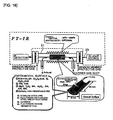
- Evaporation dishes having the surfaces of various measurement samples 22 are inserted into a tube furnace 21 shown in Fig. 18 and the temperature of the tube furnace is raised while feeding a N 2 gas, thereby detecting infrared absorption spectra of the evaporated measurement sample 22, for example, Alq3 molecules, by the use of an FT-IR.
- the tube furnace 21 is a 1/2-inch stainless pipe.
- the N 2 gas is fed at 5cc/min in order to prevent deposition of Alq3 molecules on a window member and the N 2 gas is fed to the tube furnace 21 at 10cc/min.
- the speed of the N 2 gas flowing in the tube furnace 21 is 2.8mm/sec at room temperature (25°C) and 7.2mm/sec at 500°C.
- the temperature of the tube furnace 21 is raised from 25°C to 600°C by 2.5°C/min.
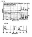
- Fig. 19, (a) and (b) show FT-IR absorption spectra when the temperature of the tube furnace 21 is raised to 382.4°C and FT-IR absorption spectra of solid Alq3 when Alq3 powder is formed into a thin layer. Although the peaks are observed only in solid Alq3 near 3400cm -1 and near 2400cm -1 , the other peaks basically coincide with each other in both. Gasified Alq3 is not decomposed/dissociated.
- Fig. 20 shows FT-IR absorption spectra of moisture (H 20 ) and a CO 2 gas. There is a high possibility that the spectra near wave numbers of 3400cm -1 and 2400cm -1 in (b) of Fig. 19 are caused by moisture or CO 2 adsorbed on solid Alq3.
- Fig. 21 shows identification of the FT-IR absorption spectra of Alq3 gasified at 382.4°C.
- Fig. 22 shows the temperature dependence of intensities of respective absorption spectra (3054cm -1 , 1599cm -1 , 748cm -1 , 1115cm -1 , and 1467cm -1 ) of Alq3 molecules in order from lower.
- Table 2 shows temperatures of decomposition/dissociation of Alq3 molecules with different surface materials of the evaporation dishes for evaporating Alq3. Resistance values of various materials in Table 2 are values measured by pushing resistance measurement terminals against various surfaces at a distance of 1cm therefrom.
- Carbon does not allow Alq3 molecules to be decomposed/dissociated up to 422.5°C, i.e. the highest temperature.
- Low-resistance SiC, TaN, AlN, BN, TiN, and MgO follow it.
- the material having as high a decomposition/dissociation start temperature as possible should be used for the evaporation dish and so on.
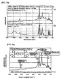
- Fig. 23 shows infrared absorption spectra of NPD molecules (C 44 H 32 N 2 ) evaporated at 417.2°C by the use of an evaporation dish with an electrolytically polished SUS316L surface and Fig. 23, (b) shows infrared absorption spectra of solid NPD. Both infrared absorption behaviors well coincide with each other except behaviors near a wave number of 3500cm -1 .
- Fig. 24 shows details of respective typical absorption spectra of NPD molecules evaporated into gas molecules. The difference in molecular structure from Alq3 appears as differences in respective absorption spectra. Fig.
- Table 3 shows temperatures at which NPD molecules start decomposition/dissociation, with respect to various materials. Like in the case of Alq3 molecules, the decomposition/dissociation start temperature by carbon is the highest, which is 452.8°C. High-resistance SiC, low-resistance SiC, AlN, MgO, Si 3 N 4 , and Al 2 O 3 follow it.
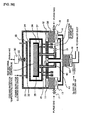
- valves 11 to 20 there are included valves 11 to 20, the process chamber 31, the substrate 32, a stage 33, a gas ejection plate 34, an organic compound molecule ejection apparatus 35, an evaporation dish 36, ringshaped gas ejection portions 37, turbo-molecular pumps 38, a temperature control heater power supply 39, and a gas temperature control roughing vacuum pump 41.
- Fig. 26 shows a sectional view of an organic film-forming apparatus in which the substrate 32 is located so as to face downward.
- the substrate 32 such as the glass substrate, the plastic substrate, or the metal substrate is held in tight contact with the stage 33 by substrate fixing means such as an electrostatic chuck so that the entire surface of the substrate is controlled uniformly and strictly at a temperature near room temperature.
- substrate fixing means such as an electrostatic chuck so that the entire surface of the substrate is controlled uniformly and strictly at a temperature near room temperature.
- the surface temperature of the stage 33 is uniformly and strictly controlled by circulating, over the entire surface of the stage, hydrogen-added cooling water removed of N 2 and O 2 dissolved from the atmosphere and added with hydrogen (H 2 ) at saturation solubility or less, for example, in an amount of 0.5 to 1.4ppm.
- the hydrogen-added water removed of N 2 and O 2 and added with H 2 has an oxidation-reduction potential (ORP) of -400mV and thus is water shifting to the reduction side by indeed as much as 1V as compared with +600mV, normally an ORP of water dissolved with N 2 and O 2 from the atmosphere, thereby not rusting metal or not breeding bacteria. Even if it is used for a long time in a hermetically sealed manner, the water quality is hardly degraded.
- ORP oxidation-reduction potential
- Fig. 27 shows the dissolution amount of metal into the hydrogen-added cooling water and, as comparison, shows the dissolution amounts of metal in air-saturated water and deaerated water being general cooling water. Cu is evaluated as the metal. It can be understood that the hydrogen-added cooling water has the effect of not corroding metal.
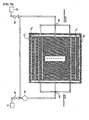
- a temperature control cooling water circulation system is constructed of copper or aluminum having high heat conductivity (high heat exchange efficiency) as shown in Fig. 28 .
- Fig. 28 there are included a substrate stage 50, flow rate controllers 51 and 57, valves 52 and 56, a compressor 53, and temperature sensors 54 and 55.
- the system is configured by keeping constant the cooling water amount flowing in the substrate stage 50, defining beforehand a correlation with a temperature T 1 (°C) at a cooling water outlet by the temperature sensor 55 to be "T 0 > T 1 ", discharging a portion of outlet-side cooling water raised in temperature into a return cooling water pipe, and introducing the same amount of cooling water from a cooling water supply pipe on the left side, thereby circulating the cooling water to the substrate stage 50 by the use of a circulation motor.
- the number (layout pitch) of temperature control cooling water pipes C 1 , C 2 , to Cn of the substrate stage 50 and the inner diameter thereof are determined in the following manner. That is, the number (layout pitch) is determined so that the difference in temperature of the substrate surface is within ⁇ 1°C and preferably within ⁇ 0.3°C. This temperature variation on the substrate surface is directly reflected on thickness variation of an organic film formed. For example, when the substrate temperature is 30°C, the temperature difference of ⁇ 0.3°C corresponds to a temperature variation of 1%.
- the inner diameter of the cooling water pipe is set to a narrow inner diameter in a region where the cooling water forms slightly turbulent flow and not laminar flow so that the cooling water flowing inside the pipe efficiently carries out heat exchange with respect to the wall surface of the pipe.
- the Reynolds number of the cooling water flowing in the cooling water pipe is desirably set in the range of 1000 to 7000.
- the cooling water pipes C 1 , C 2 , to Cn are arranged in parallel. Unless the same amount of the cooling water flows in all the cooling water pipes, the temperature of the substrate surface is not maintained uniform.
- the inner diameter of the cooling water pipe should be controlled quite accurately.
- the inner diameter should be controlled with an accuracy within ⁇ 1%.
- the size of a large-area substrate subjected to organic film formation is 1m, 2m, ..., or 5m or more. Therefore, the substrate stage becomes quite large. It is not easy to accurately control the inner diameter of a long narrow pipe. Even in that case, the cooling water amount flowing in all the cooling water pipes should be the same. Assuming that the flow rate is constant, a pressure drop Pd of cooling water in a region of slightly turbulent flow depends on an inner diameter D and a length L of a cooling water pipe as follows.
- a total pressure drop Pt of this pipe is the sum of a pressure drop Pt1 at the cooling water pipe portion and a pressure drop Pt2 at the narrow pipe portion.
- the narrow pipe portion pressure drop L2/D2 6 By setting the narrow pipe portion pressure drop L2/D2 6 to be greater than the cooling water pipe portion pressure drop L1/D1 a , pressure drop variation is determined only by the narrow pipe portion inner diameter accuracy, so that in all the cooling water pipes the cooling water amount for each pipe can be the same.
- the inner diameter of a narrow pipe having a very short length can be controlled, for example, at approximately ⁇ 0.1%.
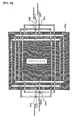
- Fig. 30 shows the case where a substrate increases in size so that a substrate stage 50A increases in size to 2m or 5m.
- the substrate stage passing time of cooling water flowing in cooling water pipes increases so that there occurs a difference between left and right temperatures of the substrate stage 50 shown in Fig. 28 .
- like cooling water pipes shown in Fig. 30 by alternating cooling water flowing directions one by one so that the cooling water flows in opposite directions, i.e. right and left directions, uniformity in temperature of the entire surface of the substrate is improved.
- the technique of equalizing the temperature of the substrate surface has been described in detail. Variation in organic film thickness due to variation in substrate surface temperature is completely suppressed by this.
- the organic compound molecule ejection apparatus 35 is comprised of carbon that does not decompose/dissociate organic compound molecules up to the highest temperature as described before, SiC, or the like.
- An organic EL material or organic compound serving as a raw material is removed of adsorbed/occluded moisture and oxygen in a high purity N 2 atmosphere at a temperature of approximately 100°C to 220°C and then is located in the evaporation dish 36 located in the organic compound molecule ejection apparatus 35.
- the evaporation dish 36 is provided with a heater so as to be raised in temperature, thereby evaporating organic EL or organic compound molecules.
- the temperature of the wall surfaces of the organic compound molecule ejection apparatus 35 and the ejection plate surrounding the evaporation dish 36 is set higher than the temperature of the evaporation dish 36 in order to prevent adsorption of organic compound molecules evaporated from the evaporation dish 36. Normally, it is set higher by 20°C to 30°C. For example, it is like when the raw material is Alq3 and the constituent material of the wall surfaces and the ejection plate is carbon, since the decomposition/dissociation temperature of the raw material is 422°C, the temperature of the evaporation dish 36 is set to 370°C to 390°C and the temperature of the outer peripheral portions (the wall surfaces and the ejection plate) is set to 400°C to 410°C.
- the evaporated organic compound molecules are confined inside the organic compound molecule ejection apparatus 35 ( Fig. 26 ).
- an organic compound molecule ejection plate 63 facing a substrate 61 is comprised of a porous material or has a shower plate structure. Naturally, the material has a high decomposition/dissociation temperature for organic compound molecules.
- the evaporation dish 36 ( Fig. 26 ) has a small heat capacity so that, for example, its temperature can be changed between 270°C to 300°C (the state where organic compound molecules are not evaporated) and 370°C to 390°C (the state where organic compound molecules are evaporated) in a short time. The temperature of the outer peripheral portions is held constant.
- the temperature of the evaporation dish 36 shown in Fig. 26 is set to a non-evaporation state, wherein the valves 11 and 12 are closed while the valve 15 is opened and the pressure inside the chamber 31 is held in a viscous flow region of 1 to 10 Torr by a gas flow rate Fch (cc/min) of Ar, N 2 , or the like flowing in from the upper portion of the chamber 31.
- Fch gas flow rate
- the evaporation dish temperature is set to an organic compound evaporation state (high temperature), wherein the valve 15 is closed, the valves 11 and 12 are opened, and the valve 20 is closed to make Fch zero, while the valve 19 is opened to supply an inert gas at approximately 100cc/min to 1,000cc/min into the organic compound molecule ejection apparatus 35, thereby ejecting a gas toward the substrate 32 through the ejection plate (porous plate or shower plate) 34.
- the ejected gas contains evaporated organic compound molecules so that the organic compound molecules are adsorbed on the substrate surface controlled at a temperature near room temperature.
- a gas having a mass greater than Ar with mass number 40 is desirable for accurately forming a gas flow pattern.
- Kr with mass number 80, Xe with mass number 131, or particularly krypton Kr is preferable.
- it may also be a mixed gas of Ar and Kr or Ar and Xe.
- the organic compound molecule ejection gas is heated to the same temperature as that of the evaporation dish 36 by a heater before flowing into the organic compound molecule ejection apparatus 35. This is for preventing occurrence of change in temperature of the evaporation dish 36.
- the pressure inside the chamber 31 during organic film formation is set to a transition flow region of approximately several mTorr to 0.1 mTorr or less. This is the range where the mean free path of gas molecules is several mm to several tens of centimeters.
- the organic compound molecule ejection gas is stopped and the temperature of the evaporation dish is dropped to the temperature of the non-film formation state.
- the valves 11 and 12 are closed, the valve 15 is opened, and the valve 20 is opened to introduce the gas such as Ar or N 2 , thereby setting the pressure inside the chamber to approximately 1 to 10 Torr.
- it is effective to feed a small amount of gas inside the organic compound molecule ejection apparatus.
- a substrate In a general substrate transfer system, a substrate is transferred while its surface to be formed with an element thereon faces upward. A complicated system is required for rotating downward, as shown in Fig. 26 , a large-area substrate that is evenly and horizontally transferred with the surface thereof facing upward. If the surface of a substrate faces upward or a substrate is stood upright, its system is relatively simple.
- Fig. 32 shows the structure where a substrate 65 is located on a stage 64 so as to face upward and is opposed to an ejection plate 66.
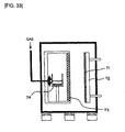
- Fig. 33 shows a sectional view of a film-forming apparatus adapted to carry out organic film formation with a structure in which a substrate 71 stood substantially vertically is located on a stage 72 and faces an ejection plate 73 and an evaporation dish 74 is disposed on the back side of the ejection plate 73.
- the same structure, operation, and effect can be achieved as those of the apparatus of Fig. 26 with the substrate facing downward and, therefore, detailed explanation thereof is omitted.
- a plurality of organic compound ejection apparatuses as shown in Fig. 26 are juxtaposed so as to be aligned laterally inside the same chamber (container to be depressurized) and a substrate is configured to be movable over them (under them in the case of Fig. 32 and on the side of them in the case of Fig. 33 ) in parallel thereto in an alignment direction.
- the substrate is stopped over (or under or on the side of) the first organic compound ejection apparatus and a first organic compound gas is ejected from the first organic compound ejection apparatus, thereby forming a film of a first organic compound layer on the substrate, and then, the substrate is automatically transferred and stopped over (or under or on the side of) the second organic compound ejection apparatus located adjacent to the first organic compound ejection apparatus and a second organic compound gas is ejected from the second organic compound ejection apparatus, thereby forming a film of a second organic compound layer on the first organic compound layer on the substrate.
- the plurality of organic compound layers can be successively formed in the same chamber.
- organic compound molecules having a certain weight i.e. a molecular weight of several hundreds to approximately 1000
- a heavy base gas such as Xe or Kr
- the gas flow accurately reaches the substrate surface, which is thus more preferable.
- the organic compound molecules, which are solidified near room temperature, are adsorbed on the substrate surface and only the Xe gas or Kr gas is discharged to the outside by the exhaust pumps.
- Xe and Kr are highly expensive gases as compared with Ar and N 2 that are normally used industrially. It is desirable that a Xe or Kr recovery circulation system be provided subsequently to the roughing vacuum pump.
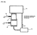
- Fig. 34 shows a system for recovering/circulating an Xe gas or a Kr gas.
- a turbo-molecular pump 77 coupled to a chamber 75 through a valve is coupled to a roughing vacuum pump 78 and the turbo-molecular pump 77 and the roughing vacuum pump 78 receive Ar or N 2 and exhaust it to a recovery apparatus 79, thereby recovering the Xe gas or Kr gas.
- the flow rate of the purge gas to the turbo-molecular pump 77 and the roughing vacuum pump 78 should be set equal to or less than that of the Xe gas or the Kr gas. Naturally, it should be necessary to prevent incorporation of evaporated components from grease used for bearings and so on of the pumps.
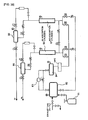
- Figs. 35 and 36 are diagrams showing the structures of Kr and Xe circulation supply apparatuses, respectively.
- a supplementary Kr bomb 81 there are included a supplementary Kr bomb 81, a low-pressure raw material tank 82, a diaphragm compressor 83, a high-pressure raw material tank 84, a GL1 (Kr adsorption cylinder) 85, a GL1 product tank 86, a GL2 (N 2 adsorption cylinder) 87, and a GL2 product tank 88.
- a supplementary Kr bomb 81 there are included a supplementary Kr bomb 81, a low-pressure raw material tank 82, a diaphragm compressor 83, a high-pressure raw material tank 84, a GL1 (Kr adsorption cylinder) 85, a GL1 product tank 86, a GL2 (N 2 adsorption cylinder) 87, and a GL2 product tank 88.
- a supplementary Xe bomb 81A there are included a supplementary Xe bomb 81A, a low-pressure raw material tank 82A, a diaphragm compressor 83A, a high-pressure raw material tank 84A, a GL1 (Xe adsorption cylinder) 85A, a GL1 product tank 86A, a GL2 (N 2 adsorption cylinder) 87A, and a GL2 product tank 88A.
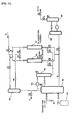
- Figs. 37 and 38 are diagrams showing the structures of circulation supply apparatuses for mixed gases of Ar and Kr, and Ar and Xe, respectively.
- a supplementary Kr bomb 91 there are included a supplementary Kr bomb 91, an Ar buffer tank 92, a low-pressure raw material tank 93, a diaphragm compressor 94, a high-pressure raw material tank 95, a GL1-1 (Kr adsorption cylinder) 96, a GL1-2 (Kr adsorption cylinder) 97, a "Kr + Ar” buffer tank 98, and a "Kr + Ar” product tank 99.
- Fig. 37 there are included a supplementary Kr bomb 91, an Ar buffer tank 92, a low-pressure raw material tank 93, a diaphragm compressor 94, a high-pressure raw material tank 95, a GL1-1 (Kr adsorption cylinder) 96, a GL1-2 (Kr adsorption cylinder
- a supplementary Xe bomb 91A there are included a supplementary Xe bomb 91A, an Ar buffer tank 92A, a low-pressure raw material tank 93A, a diaphragm compressor 94A, a high-pressure raw material tank 95A, a GL1-1 (Xe adsorption cylinder) 96A, a GL1-2 (Xe adsorption cylinder) 97A, a "Xe + Ar” buffer tank 98A, and a "Xe + Ar” product tank 99A.
- the adsorption cylinder is provided therein with an adsorbent for adsorbing impurities such as noble gas components or nitrogen and Xe or Kr is separated/purified by changing the pressure inside the adsorption cylinder to repeat adsorption/desorption.
- the lifetime and luminous properties of an organic EL element can be improved by removing organic compound contamination of an organic EL thin film.
- the lifetime and luminous properties can be further improved.
- the substrate surface (the surface to be deposited with a film-forming material) faces upward in the film-forming apparatus
- the substrate surface face upward during gas levitation transfer
- the substrate surface faces downward in the film-forming apparatus
- the substrate surface face downward during gas levitation transfer
- the substrate surface face upward or downward during gas levitation transfer
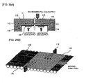
- Figs. 39A and 39B show an example where a substrate is transferred to a film-forming apparatus by the use of a gas levitation transfer system using a clean dry air.
- a casing 111 there are included a casing 111, soft X-ray ionizers 112, soft X-rays 113, driving rollers 114, a glass substrate 115, and levitation ceramics 116.
- the substrate is levitated/transferred in a clean dry air atmosphere containing no moisture or no organic compound, not only ultrahigh-quality film formation is enabled because moisture or organic compound are not adsorbed at all on the outermost surface of the substrate, but also static electricity is not carried at all in gas levitation transfer using porous ceramics and, therefore, a problem such as dielectric breakdown or disconnection in an element or at element peripheral portions can be reduced, thereby enabling an improvement in production yield and a reduction in production cost.
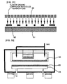
- FIG. 40 is a sectional view showing one example of a deposition apparatus of this Embodiment 4, wherein the apparatus mainly comprises a container forming a process chamber 125 adapted to carry out a film-forming process, a substrate introduction chamber 123 coupled to the process chamber 125 through a gate valve 124 serving as a partition for the depressurizing chamber and maintaining airtightness of the process chamber 125, so as to carry in and out a substrate 131, a substrate introduction door 121 coupled to the substrate introduction chamber 123, a substrate holder 132 adapted to hold the substrate 131 in the container, primary pumps 127 coupled to the depressurizing chamber and the substrate introduction chamber 123 through pump gate valves 126, respectively, secondary pumps 130 coupled to exhaust sides of the primary pumps 127, pump purge gas introduction mechanisms 128 and 129 each located between the primary pump 127 and the secondary pump 130 for suppressing back diffusion of impurities from the secondary pump
- the gaskets 122 provided between the substrate introduction door 121 and the substrate introduction chamber 123 and between a deposition source chamber and a shutter mechanism are comprised of perfluoroelastomer and the other gaskets are comprised of Cu.
- the deposition source container is comprised of Al 2 O 3 and its inner surfaces are made substantially flat by polishing, and therefore, there is almost no catalysis so that it is possible to suppress thermal decomposition of the deposition material inside the deposition source container.
- the brightness at the same current was improved by 30% as compared with the case of using conventional ones (general fluororubber gaskets and a general deposition source container) and the luminance half-decay lifetime became twice, i.e. 10000 hours. Since the organic compound release from the gaskets is suppressed and the decomposition of the deposition material in the deposition source container is suppressed, the incorporation of the impurities into the organic EL layer is suppressed. Therefore, it was possible to improve the brightness and the lifetime.
- the film-forming conditions can be controlled by the flow of the gas and hence a uniform thin film can be deposited on the large-area substrate.
- the film-forming apparatus of this invention thoroughly eliminates generation of the organic compound contamination substance/material decomposition dissociation substance that adversely affects the properties of the film-forming material, and thus can deposit a high-quality thin film.
- the film-forming apparatus and the film-forming method of this invention for forming an organic EL element, it is possible to obtain a high-quality organic EL display device with high brightness and long lifetime.
- the film-forming apparatus and the film-forming method of this invention are effectively applicable not only to the organic EL field but also to all the other fields where raw materials are evaporated to form films with respect to flat panel display devices, semiconductor devices, and other general electronic devices.
Landscapes
- Chemical & Material Sciences (AREA)
- Engineering & Computer Science (AREA)
- Mechanical Engineering (AREA)
- Chemical Kinetics & Catalysis (AREA)
- Materials Engineering (AREA)
- Metallurgy (AREA)
- Organic Chemistry (AREA)
- Physics & Mathematics (AREA)
- Thermal Sciences (AREA)
- General Engineering & Computer Science (AREA)
- Physical Vapour Deposition (AREA)
- Electroluminescent Light Sources (AREA)
Claims (36)
- Appareil de formation de film caractérisé en ce qu'il comprend un récipient (31) devant être dépressurisé, un mécanisme de dépressurisation (38, 41) couplé directement ou indirectement audit récipient (31), un appareil de fourniture de matière de formation de film (34-37) situé à l'intérieur ou à l'extérieur dudit récipient (31) et couplé directement ou indirectement audit récipient (31) pour fournir une matière de formation de film ou un précurseur de matière de formation de film, et une partie de mise en place de substrat (33) située dans ledit récipient (31) pour la mise en place d'un substrat (32) sur lequel la matière de formation de film est déposée, dans lequel ledit appareil de fourniture de matière de formation de film (34-37) possède au moins un mécanisme d'évaporation (35, 36) pour assurer l'évaporation de ladite matière de formation de film ou dudit précurseur de matière de formation de film et une partie dudit mécanisme d'évaporation (35, 36), avec laquelle ladite matière de formation de film ou ledit précurseur de matière de formation de film doit être mis(e) en contact, est composée d'une matière ayant une faible décharge de gaz ou d'une matière ayant un faible effet catalytique ;
dans lequel ladite matière ayant une faible décharge de gaz est définie comme générant du gaz à une température d'évaporation de la matière de formation de film dans une quantité inférieure ou égale à une quantité de gaz générée par la matière SUS-316L ayant la même forme et ayant une surface polie électrolytiquement à la même température ou comme générant du gaz dans ledit appareil de formation de film dans une quantité correspondant à une pression partielle ne dépassant pas 1/10 d'une pression de formation de film ;
dans lequel ladite matière ayant un faible effet catalytique est définie comme présentant, lorsqu'elle est mise en contact avec ladite matière de formation de film ou ledit précurseur de matière de formation de film et que sa température est augmentée, une température de décomposition de matière pour ladite matière de formation de film ou ledit précurseur de matière de formation de film supérieure ou égale à celle de la matière SUS-316L ayant la même forme et ayant une surface polie électrolytiquement ou comme présentant une différence de température de 20°C ou moins entre une température de début de décomposition présentée par ladite matière de formation de film ou ledit précurseur de matière de formation de film seul et une température de début de décomposition présentée par ladite matière de formation de film ou ledit précurseur de matière de formation de film lors de sa mise en contact avec ladite matière ; et
dans lequel ledit mécanisme d'évaporation (35, 36) comprend un mécanisme de chauffage pour chauffer ladite matière de formation de film ou ledit précurseur de matière de formation de film à une première température supérieure ou égale à une température d'évaporation à laquelle ladite matière de formation de film ou ledit précurseur de matière de formation de film est évaporé(e), et des moyens de chauffage pour chauffer une partie prédéterminée à l'intérieur dudit récipient (31) à une deuxième température dépassant ladite première température, ladite partie prédéterminée étant une partie adaptée pour être en contact avec la matière de formation de film ou le précurseur de matière de formation de film évaporé(e) et excluant ledit substrat (32) et ladite partie de maintien de substrat (33). - Appareil de formation de film selon la revendication 1, caractérisé en ce qu'il comprend un mécanisme de fourniture de gaz de transport (34, 37) pour fournir un gaz qui transporte la matière de formation de film ou le précurseur de matière de formation de film vers une surface dudit substrat (32).
- Appareil de formation de film selon la revendication 1, caractérisé en ce qu'une température dudit substrat (32) est maintenue à une troisième température inférieure à ladite température d'évaporation.
- Appareil de formation de film selon la revendication 1, caractérisé en ce que ladite première température et ladite deuxième température sont inférieures à une température à laquelle la matière de formation de film ou le précurseur de matière de formation de film est décomposé.
- Appareil de formation de film selon la revendication 1, caractérisé en ce que ladite deuxième température est supérieure à ladite première température de 20°C ou plus.
- Appareil de formation de film selon la revendication 3, caractérisé en ce que ladite troisième température est inférieure ou égale à ladite température d'évaporation.
- Appareil de formation de film selon la revendication 6, caractérisé en ce que ladite matière de formation de film est une matière pour EL organique et ladite troisième température est inférieure à 100°C.
- Appareil de formation de film selon la revendication 2, caractérisé en ce que ledit mécanisme de fourniture de gaz de transport (34, 37) comprend une partie (37) adaptée pour introduire ledit gaz de transport depuis l'extérieur dans un récipient contenant ladite matière de formation de film ou ledit précurseur de matière de formation de film et une partie d'éjection de gaz (34) ayant une pluralité de petits trous et positionnée de sorte à faire face audit substrat (32), et ledit gaz transporte ladite matière de formation de film ou ledit précurseur de matière de formation de film évaporé(e) vers la surface dudit substrat (32) à travers ladite partie d'éjection de gaz (34).
- Appareil de formation de film selon la revendication 2, caractérisé en ce que ledit mécanisme de fourniture de gaz de transport (34, 37) comprend un mécanisme (37) pour fournir ledit gaz de transport depuis l'extérieur de sorte qu'il entre en contact avec ladite matière de formation de film ou ledit précurseur de matière de formation de film et un mécanisme (34) pour éjecter le gaz de transport contenant ladite matière de formation de film ou ledit précurseur de matière de formation de film vers ledit substrat.
- Appareil de formation de film selon la revendication 9, caractérisé en ce que ledit mécanisme d'éjection (34) comprend une plaque de douche ou une plaque composée d'une matière poreuse.
- Appareil de formation de film selon la revendication 1, caractérisé en ce que ledit mécanisme d'évaporation (35, 36) est configuré pour assurer l'évaporation de ladite matière de formation de film ou dudit précurseur de matière de formation de film lors de l'exécution de la formation de film et pour arrêter l'évaporation lors de la non-exécution de la formation de film.
- Appareil de formation de film selon la revendication 1, caractérisé en ce que ledit mécanisme de dépressurisation (38, 41) maintient l'intérieur dudit récipient (31) à une pression de 10 mTorr à 0,1 mTorr lors de l'exécution de la formation de film.
- Appareil de formation de film selon la revendication 12, caractérisé en ce que lesdits moyens de dépressurisation (38, 41) agissent sur un écoulement de gaz dans ledit récipient (31) pour qu'il se trouve dans une région d'écoulement moléculaire lors de l'exécution de la formation de film et agissent sur un écoulement de gaz dans ledit récipient pour qu'il se trouve dans une région d'écoulement intermédiaire ou une région d'écoulement visqueuse au moins pendant une certaine période lors de la non-exécution de la formation de film.
- Appareil de formation de film selon la revendication 9, caractérisé en ce que ledit gaz est un gaz xénon (Xe).
- Appareil de formation de film selon la revendication 2, caractérisé en ce que ledit gaz contient un gaz inerte comme composant principal.
- Appareil de formation de film selon la revendication 2, caractérisé en ce que ledit gaz contient au moins l'un parmi azote (N), Xe, Kr, Ar, Ne et He.
- Appareil de formation de film selon la revendication 1, caractérisé en ce que ledit mécanisme de dépressurisation (38, 41). comprend une pompe turbomoléculaire (38) et une pompe de prévidage (41) et une partie pour fournir un gaz inerte est prévue entre ladite pompe turbomoléculaire (38) et ladite pompe de prévidage (41).
- Appareil de formation de film selon la revendication 1, caractérisé en ce qu'une pression dans ledit récipient (31) lors de la formation de film et qu'une pression lors de la non-formation de film se trouvent dans une région de pression d'écoulement moléculaire et une région de pression d'écoulement intermédiaire ou une région de pression d'écoulement visqueuse, respectivement.
- Procédé de formation de film pour déposer un film d'une matière prédéterminée sur un substrat en utilisant l'appareil de formation de film selon la revendication 1, ledit procédé de formation de film étant caractérisé en ce qu'il comprend une étape d'évaporation d'une matière première utilisée pour former ledit film de la matière prédéterminée et une étape de transport de ladite matière première évaporée vers une surface dudit substrat (32) grâce à l'utilisation d'un gaz.
- Procédé de formation de film selon la revendication 19, caractérisé en ce que ladite étape d'évaporation comprend une étape de chauffage de ladite matière première à une première température supérieure ou égale à une température à laquelle ladite matière première est évaporée, et une étape de chauffage d'une partie prédéterminée à l'intérieur dudit récipient (31) à une deuxième température supérieure à ladite température à laquelle ladite matière première est évaporée.
- Procédé de formation de film selon la revendication 20, caractérisé en ce qu'une température dudit substrat (32) est maintenue à une troisième température inférieure à ladite température à laquelle ladite matière première est évaporée.
- Procédé de formation de film selon la revendication 20, caractérisé en ce que ladite première température et ladite deuxième température sont inférieures à une température à laquelle la matière première évaporée est décomposée.
- Procédé de formation de film selon la revendication 22, caractérisé en ce que ladite deuxième température est supérieure à ladite première température.
- Procédé de formation de film selon la revendication 22, caractérisé en ce que ladite deuxième température est supérieure à ladite première température de 20°C ou plus.
- Procédé de formation de film selon la revendication 21, caractérisé en ce que ladite troisième température est inférieure ou égale à ladite température à laquelle ladite matière première est évaporée.
- Procédé de formation de film selon la revendication 21, caractérisé en ce que ladite matière prédéterminée est une matière EL organique et ladite troisième température est inférieure à 100°C.
- Procédé de formation de film selon la revendication 19, caractérisé en ce que ladite matière première est ladite matière prédéterminée ou un précurseur de ladite matière prédéterminée.
- Procédé de formation de film selon la revendication 19, caractérisé par la mise en place de ladite matière première dans un récipient résistant à la chaleur, la mise en place dudit récipient résistant à la chaleur dans un récipient de gaz, l'introduction dudit gaz dans ledit récipient de gaz pour transporter ladite matière première évaporée grâce à l'utilisation dudit gaz, et l'action sur ledit gaz pour qu'il atteigne la surface dudit substrat à travers une partie d'éjection de gaz (34) tout en transportant ladite matière première évaporée, dans lequel ladite partie d'éjection de gaz (34) ayant une pluralité de petits trous est positionnée de sorte à faire face audit substrat (32).
- Procédé de formation de film selon la revendication 19, caractérisé par le maintien de l'intérieur dudit récipient (31) à une pression de 10 mTorr à 0,1 mTorr lors de l'exécution de la formation de film et le maintien de l'intérieur dudit récipient (31) à une pression réduite de 1 Torr ou plus au moins pendant une certaine période lors de la non-exécution de la formation de film.
- Procédé de formation de film selon la revendication 19, caractérisé en ce qu'il agit sur un écoulement de gaz dans ledit récipient (31) pour qu'il se trouve dans une région d'écoulement moléculaire lors de l'exécution de la formation de film et en ce qu'il agit sur un écoulement de gaz dans ledit récipient (31) pour qu'il se trouve dans une région d'écoulement intermédiaire ou une région d'écoulement visqueuse au moins pendant une certaine période lors de la non-exécution de la formation de film.
- Procédé de formation de film selon la revendication 19, caractérisé en ce que ledit gaz est un gaz xénon (Xe).
- Procédé de formation de film selon la revendication 19, caractérisé en ce que ledit gaz contient un gaz inerte comme composant principal.
- Procédé de formation de film selon la revendication 32, caractérisé en ce que ledit gaz inerte contient au moins l'un parmi azote (N), Xe, Kr, Ar, Ne et He.
- Procédé de formation de film selon la revendication 19, caractérisé en ce que ladite matière prédéterminée est une matière d'élément EL organique.
- Procédé de fabrication de dispositif EL organique caractérisé en ce qu'il comprend une étape de formation d'une matière d'élément EL organique grâce à l'utilisation du procédé de formation de film selon la revendication 19.
- Procédé de fabrication de dispositif électronique caractérisé en ce qu'il comprend une étape de formation d'une couche de film d'une matière prédéterminée grâce à l'utilisation du procédé de formation de film selon la revendication 19.
Applications Claiming Priority (2)
| Application Number | Priority Date | Filing Date | Title |
|---|---|---|---|
| JP2004097112 | 2004-03-29 | ||
| PCT/JP2005/005928 WO2005093120A1 (fr) | 2004-03-29 | 2005-03-29 | Appareil de formation de film et procédé de formation de film |
Publications (3)
| Publication Number | Publication Date |
|---|---|
| EP1741802A1 EP1741802A1 (fr) | 2007-01-10 |
| EP1741802A4 EP1741802A4 (fr) | 2009-08-19 |
| EP1741802B1 true EP1741802B1 (fr) | 2013-08-21 |
Family
ID=35056224
Family Applications (1)
| Application Number | Title | Priority Date | Filing Date |
|---|---|---|---|
| EP05727877.2A Expired - Lifetime EP1741802B1 (fr) | 2004-03-29 | 2005-03-29 | Appareil de formation de film et procede de formation de film |
Country Status (7)
| Country | Link |
|---|---|
| US (1) | US20080241587A1 (fr) |
| EP (1) | EP1741802B1 (fr) |
| JP (1) | JP5191656B2 (fr) |
| KR (1) | KR100830388B1 (fr) |
| CN (1) | CN1938447B (fr) |
| TW (1) | TWI371501B (fr) |
| WO (1) | WO2005093120A1 (fr) |
Cited By (1)
| Publication number | Priority date | Publication date | Assignee | Title |
|---|---|---|---|---|
| DE102015107297A1 (de) * | 2015-05-11 | 2016-11-17 | Von Ardenne Gmbh | Prozessieranordnung |
Families Citing this family (32)
| Publication number | Priority date | Publication date | Assignee | Title |
|---|---|---|---|---|
| EP1862788A1 (fr) * | 2006-06-03 | 2007-12-05 | Applied Materials GmbH & Co. KG | Evaporateur pour matériau organique, installation de revêtement et leur procédé d'utilisation |
| CN101803462B (zh) * | 2007-09-10 | 2012-06-27 | 株式会社爱发科 | 蒸气放出装置、有机薄膜蒸镀装置及有机薄膜蒸镀方法 |
| US11975546B2 (en) | 2008-06-13 | 2024-05-07 | Kateeva, Inc. | Gas enclosure assembly and system |
| US9048344B2 (en) | 2008-06-13 | 2015-06-02 | Kateeva, Inc. | Gas enclosure assembly and system |
| US9604245B2 (en) | 2008-06-13 | 2017-03-28 | Kateeva, Inc. | Gas enclosure systems and methods utilizing an auxiliary enclosure |
| US10442226B2 (en) | 2008-06-13 | 2019-10-15 | Kateeva, Inc. | Gas enclosure assembly and system |
| US8383202B2 (en) | 2008-06-13 | 2013-02-26 | Kateeva, Inc. | Method and apparatus for load-locked printing |
| US8899171B2 (en) | 2008-06-13 | 2014-12-02 | Kateeva, Inc. | Gas enclosure assembly and system |
| US12064979B2 (en) | 2008-06-13 | 2024-08-20 | Kateeva, Inc. | Low-particle gas enclosure systems and methods |
| US12018857B2 (en) | 2008-06-13 | 2024-06-25 | Kateeva, Inc. | Gas enclosure assembly and system |
| US10434804B2 (en) | 2008-06-13 | 2019-10-08 | Kateeva, Inc. | Low particle gas enclosure systems and methods |
| DE112009002468B4 (de) | 2008-11-14 | 2020-01-02 | Ulvac, Inc. | Dünnschicht-Niederschlagsvorrichtung, organische EL-Element-Herstellungsvorrichtung und organische Dünnschicht-Niederschlagsverfahren |
| JP5696530B2 (ja) * | 2010-05-01 | 2015-04-08 | 東京エレクトロン株式会社 | 薄膜の形成方法及び成膜装置 |
| JP5792438B2 (ja) * | 2010-08-12 | 2015-10-14 | 東京エレクトロン株式会社 | 成膜装置及び成膜方法 |
| US9120344B2 (en) | 2011-08-09 | 2015-09-01 | Kateeva, Inc. | Apparatus and method for control of print gap |
| KR20190101506A (ko) | 2011-08-09 | 2019-08-30 | 카티바, 인크. | 하향 인쇄 장치 및 방법 |
| JP5994080B2 (ja) * | 2012-04-13 | 2016-09-21 | 株式会社Joled | 真空装置、有機膜の形成方法、有機el素子の製造方法、有機el表示パネル、有機el表示装置、有機el発光装置およびゲッター材を構成する材料の選択方法 |
| WO2014045904A1 (fr) * | 2012-09-21 | 2014-03-27 | コニカミノルタ株式会社 | Procédé de fabrication de produit de verre |
| WO2015100375A1 (fr) | 2013-12-26 | 2015-07-02 | Kateeva, Inc. | Traitement thermique de dispositifs électroniques |
| WO2015112454A1 (fr) | 2014-01-21 | 2015-07-30 | Kateeva, Inc. | Appareils et techniques d'encapsulation de dispositifs électroniques |
| US9343678B2 (en) | 2014-01-21 | 2016-05-17 | Kateeva, Inc. | Apparatus and techniques for electronic device encapsulation |
| KR102850075B1 (ko) | 2014-04-30 | 2025-08-25 | 카티바, 인크. | 가스 쿠션 장비 및 기판 코팅 기술 |
| JP6021210B2 (ja) * | 2014-05-23 | 2016-11-09 | 株式会社シンクロン | 薄膜の成膜方法及び成膜装置 |
| CN104313542B (zh) * | 2014-10-24 | 2016-09-28 | 京东方科技集团股份有限公司 | Ito层及ito图案的制作方法、显示基板及显示装置 |
| WO2016086192A1 (fr) | 2014-11-26 | 2016-06-02 | Kateeva, Inc. | Systèmes de revêtement environnementalement maîtrisés |
| JP6450469B2 (ja) * | 2015-11-10 | 2019-01-09 | 東京エレクトロン株式会社 | 気化器、成膜装置及び温度制御方法 |
| CN105316626A (zh) * | 2015-11-20 | 2016-02-10 | 苏州赛森电子科技有限公司 | 半导体加工用蒸发台的镀膜原料导向装置 |
| CN108474115B (zh) * | 2015-12-24 | 2021-04-23 | 株式会社Flosfia | 成膜方法 |
| KR102369676B1 (ko) | 2017-04-10 | 2022-03-04 | 삼성디스플레이 주식회사 | 표시 장치의 제조장치 및 표시 장치의 제조방법 |
| CN110047774B (zh) * | 2018-01-17 | 2021-08-27 | 杭州纤纳光电科技有限公司 | 一种沉浸式制备钙钛矿薄膜的设备及使用方法和应用 |
| US20250051924A1 (en) * | 2021-12-22 | 2025-02-13 | University Of Maryland, College Park | Vapor deposition systems and methods, and nanomaterials formed by vapor deposition |
| CN119372597B (zh) * | 2024-09-30 | 2025-04-22 | 宁波汉科医疗器械有限公司 | 一种用于口腔隐形矫治器的高附着力抗菌膜的制备方法 |
Family Cites Families (38)
| Publication number | Priority date | Publication date | Assignee | Title |
|---|---|---|---|---|
| US3640689A (en) * | 1970-03-04 | 1972-02-08 | Fansteel Inc | Composite hard metal product |
| US5019531A (en) * | 1988-05-23 | 1991-05-28 | Nippon Telegraph And Telephone Corporation | Process for selectively growing thin metallic film of copper or gold |
| US5180436A (en) * | 1988-07-26 | 1993-01-19 | Matsushita Electric Industrial Co., Ltd. | Microwave plasma film deposition system |
| JPH0780718B2 (ja) * | 1989-08-04 | 1995-08-30 | トヨタ自動車株式会社 | ダイヤモンドの合成方法および合成装置 |
| US5054420A (en) * | 1989-09-29 | 1991-10-08 | Alcan International Limited | Use of a particulate packed bed at the inlet of a vertical tube MOCVD reactor to achieve desired gas flow characteristics |
| US5160544A (en) * | 1990-03-20 | 1992-11-03 | Diamonex Incorporated | Hot filament chemical vapor deposition reactor |
| US5071678A (en) * | 1990-10-09 | 1991-12-10 | United Technologies Corporation | Process for applying gas phase diffusion aluminide coatings |
| JPH0811718B2 (ja) * | 1992-02-27 | 1996-02-07 | 大同ほくさん株式会社 | ガスソース分子線エピタキシー装置 |
| JP3404109B2 (ja) * | 1994-02-24 | 2003-05-06 | 第一製薬株式会社 | 薬液充填済みプラスチック製シリンジ製剤の製造方法 |
| JP3501524B2 (ja) * | 1994-07-01 | 2004-03-02 | 東京エレクトロン株式会社 | 処理装置の真空排気システム |
| US5925189A (en) * | 1995-12-06 | 1999-07-20 | Applied Materials, Inc. | Liquid phosphorous precursor delivery apparatus |
| JPH09279346A (ja) * | 1996-04-17 | 1997-10-28 | Central Glass Co Ltd | 粉体の気化方法及びその装置 |
| US6143081A (en) * | 1996-07-12 | 2000-11-07 | Tokyo Electron Limited | Film forming apparatus and method, and film modifying apparatus and method |
| JP3788835B2 (ja) * | 1996-12-06 | 2006-06-21 | 株式会社アルバック | 有機薄膜製造方法 |
| JPH11189862A (ja) | 1997-12-26 | 1999-07-13 | Nippon Paint Co Ltd | 有機着色薄膜の製造法 |
| JP3643474B2 (ja) * | 1998-01-30 | 2005-04-27 | 株式会社東芝 | 半導体処理システム及び半導体処理システムの使用方法 |
| JP2000104172A (ja) * | 1998-07-28 | 2000-04-11 | Toshiba Corp | 成膜方法,成膜装置及び固形原料 |
| US6202591B1 (en) * | 1998-11-12 | 2001-03-20 | Flex Products, Inc. | Linear aperture deposition apparatus and coating process |
| JP4469430B2 (ja) * | 1998-11-30 | 2010-05-26 | 株式会社アルバック | 蒸着装置 |
| JP3682465B2 (ja) * | 1999-03-31 | 2005-08-10 | 独立行政法人産業技術総合研究所 | 樹脂成形物表面層の改質方法およびそのための装置および表面層が改質された樹脂成形物、および樹脂成形物表面層の着色方法およびそのための装置および表面層が着色された樹脂成形物、および表面層の改質により機能性を付与された樹脂成形物 |
| IL134891A0 (en) * | 2000-03-06 | 2001-05-20 | Yeda Res & Dev | Reactors for production of tungsten disulfide hollow onion-like nanoparticles |
| US6863019B2 (en) * | 2000-06-13 | 2005-03-08 | Applied Materials, Inc. | Semiconductor device fabrication chamber cleaning method and apparatus with recirculation of cleaning gas |
| JP2002194548A (ja) * | 2000-12-28 | 2002-07-10 | Toshiba Corp | ガス供給方法 |
| JP4906018B2 (ja) * | 2001-03-12 | 2012-03-28 | 株式会社半導体エネルギー研究所 | 成膜方法、発光装置の作製方法及び成膜装置 |
| JP4335469B2 (ja) * | 2001-03-22 | 2009-09-30 | 株式会社荏原製作所 | 真空排気装置のガス循環量調整方法及び装置 |
| JP2003068713A (ja) * | 2001-08-24 | 2003-03-07 | Matsushita Electric Ind Co Ltd | プラズマ処理装置 |
| EP1423552B1 (fr) * | 2001-09-04 | 2015-10-21 | The Trustees Of Princeton University | Procede pour le depot sous jet de vapeur organique |
| JP4294305B2 (ja) * | 2001-12-12 | 2009-07-08 | 株式会社半導体エネルギー研究所 | 成膜装置および成膜方法 |
| SG114589A1 (en) * | 2001-12-12 | 2005-09-28 | Semiconductor Energy Lab | Film formation apparatus and film formation method and cleaning method |
| KR100447248B1 (ko) * | 2002-01-22 | 2004-09-07 | 주성엔지니어링(주) | Icp 에쳐용 가스 확산판 |
| JP3754380B2 (ja) * | 2002-02-06 | 2006-03-08 | 株式会社エイコー・エンジニアリング | 薄膜堆積用分子線源セルと薄膜堆積方法 |
| DE10212923A1 (de) * | 2002-03-22 | 2004-01-08 | Aixtron Ag | Verfahren zum Beschichten eines Substrates und Vorrichtung zur Durchführung des Verfahrens |
| JP2004010989A (ja) * | 2002-06-10 | 2004-01-15 | Sony Corp | 薄膜形成装置 |
| JP2004010990A (ja) * | 2002-06-10 | 2004-01-15 | Sony Corp | 薄膜形成装置 |
| JP4120285B2 (ja) * | 2002-06-13 | 2008-07-16 | 東京エレクトロン株式会社 | 被処理体の導入ポート機構及びこれを用いた処理システム |
| JP4239520B2 (ja) * | 2002-08-21 | 2009-03-18 | ソニー株式会社 | 成膜装置およびその製造方法、並びにインジェクタ |
| JP5107500B2 (ja) | 2003-08-20 | 2012-12-26 | 公益財団法人国際科学振興財団 | 蒸着装置 |
| US7132128B2 (en) * | 2005-03-31 | 2006-11-07 | Tokyo Electron Limited | Method and system for depositing material on a substrate using a solid precursor |
-
2005
- 2005-03-29 EP EP05727877.2A patent/EP1741802B1/fr not_active Expired - Lifetime
- 2005-03-29 US US10/594,495 patent/US20080241587A1/en not_active Abandoned
- 2005-03-29 KR KR1020067022081A patent/KR100830388B1/ko not_active Expired - Fee Related
- 2005-03-29 CN CN2005800099904A patent/CN1938447B/zh not_active Expired - Fee Related
- 2005-03-29 TW TW094109705A patent/TWI371501B/zh active
- 2005-03-29 JP JP2006511584A patent/JP5191656B2/ja not_active Expired - Fee Related
- 2005-03-29 WO PCT/JP2005/005928 patent/WO2005093120A1/fr not_active Ceased
Cited By (1)
| Publication number | Priority date | Publication date | Assignee | Title |
|---|---|---|---|---|
| DE102015107297A1 (de) * | 2015-05-11 | 2016-11-17 | Von Ardenne Gmbh | Prozessieranordnung |
Also Published As
| Publication number | Publication date |
|---|---|
| CN1938447A (zh) | 2007-03-28 |
| TWI371501B (en) | 2012-09-01 |
| US20080241587A1 (en) | 2008-10-02 |
| JP5191656B2 (ja) | 2013-05-08 |
| EP1741802A1 (fr) | 2007-01-10 |
| TW200535270A (en) | 2005-11-01 |
| KR100830388B1 (ko) | 2008-05-20 |
| KR20070000500A (ko) | 2007-01-02 |
| WO2005093120A1 (fr) | 2005-10-06 |
| EP1741802A4 (fr) | 2009-08-19 |
| JPWO2005093120A1 (ja) | 2008-02-14 |
| CN1938447B (zh) | 2010-06-09 |
Similar Documents
| Publication | Publication Date | Title |
|---|---|---|
| EP1741802B1 (fr) | Appareil de formation de film et procede de formation de film | |
| KR20060136470A (ko) | 막 형성 장치 및 막 형성 방법 | |
| US6770562B2 (en) | Film formation apparatus and film formation method | |
| EP3799141B1 (fr) | Appareil et procédé d'impression de films minces multicouches en phase vapeur dans une atmosphère gazeuse pure | |
| CN100565784C (zh) | 制造设备 | |
| US7632550B2 (en) | Film forming method employing reactive and reducing gases and substrate formed by the method | |
| EP1443127B1 (fr) | Procédé pour rêveter de substrats de la surface grande | |
| CN100380672C (zh) | 发光器件 | |
| CN101809188B (zh) | 用于形成薄膜密封层的工艺 | |
| US6946406B2 (en) | Film forming apparatus and film forming method | |
| US20110268870A1 (en) | Film forming apparatus and film forming method | |
| CN101103136B (zh) | 真空处理装置 | |
| CN1961095B (zh) | 用以沉积低温无机层至大型塑胶基板上的方法及其设备 | |
| US20100166956A1 (en) | Vapor deposition apparatus | |
| JP2013131542A (ja) | インライン式成膜装置 | |
| JP4368633B2 (ja) | 製造装置 | |
| US20040121086A1 (en) | Thin film depositing method and apparatus | |
| KR100707960B1 (ko) | 투명 전극용 아이티오 복합층 형성을 위한 인라인 스퍼터링장치 | |
| CN1659303A (zh) | 形成有机薄膜的方法 | |
| JP6336146B2 (ja) | インライン式成膜装置、および、成膜方法 | |
| US20150064483A1 (en) | Metal deposition using organic vapor phase deposition (vpd) system | |
| TW202142674A (zh) | 量子點構造體及量子點構造體之製造方法 | |
| JP2019131869A (ja) | 蒸着装置 | |
| CN87104355A (zh) | 多室淀积系统 | |
| KR100640160B1 (ko) | 반도체소자용 제조 장치 |
Legal Events
| Date | Code | Title | Description |
|---|---|---|---|
| PUAI | Public reference made under article 153(3) epc to a published international application that has entered the european phase |
Free format text: ORIGINAL CODE: 0009012 |
|
| 17P | Request for examination filed |
Effective date: 20061016 |
|
| AK | Designated contracting states |
Kind code of ref document: A1 Designated state(s): DE FR GB IT |
|
| DAX | Request for extension of the european patent (deleted) | ||
| RBV | Designated contracting states (corrected) |
Designated state(s): DE FR GB IT |
|
| A4 | Supplementary search report drawn up and despatched |
Effective date: 20090717 |
|
| 17Q | First examination report despatched |
Effective date: 20100329 |
|
| GRAP | Despatch of communication of intention to grant a patent |
Free format text: ORIGINAL CODE: EPIDOSNIGR1 |
|
| GRAS | Grant fee paid |
Free format text: ORIGINAL CODE: EPIDOSNIGR3 |
|
| GRAA | (expected) grant |
Free format text: ORIGINAL CODE: 0009210 |
|
| AK | Designated contracting states |
Kind code of ref document: B1 Designated state(s): DE FR GB IT |
|
| REG | Reference to a national code |
Ref country code: GB Ref legal event code: FG4D |
|
| REG | Reference to a national code |
Ref country code: DE Ref legal event code: R096 Ref document number: 602005040952 Country of ref document: DE Effective date: 20131010 |
|
| PG25 | Lapsed in a contracting state [announced via postgrant information from national office to epo] |
Ref country code: IT Free format text: LAPSE BECAUSE OF FAILURE TO SUBMIT A TRANSLATION OF THE DESCRIPTION OR TO PAY THE FEE WITHIN THE PRESCRIBED TIME-LIMIT Effective date: 20130821 |
|
| PLBE | No opposition filed within time limit |
Free format text: ORIGINAL CODE: 0009261 |
|
| STAA | Information on the status of an ep patent application or granted ep patent |
Free format text: STATUS: NO OPPOSITION FILED WITHIN TIME LIMIT |
|
| 26N | No opposition filed |
Effective date: 20140522 |
|
| REG | Reference to a national code |
Ref country code: DE Ref legal event code: R097 Ref document number: 602005040952 Country of ref document: DE Effective date: 20140522 |
|
| GBPC | Gb: european patent ceased through non-payment of renewal fee |
Effective date: 20140329 |
|
| REG | Reference to a national code |
Ref country code: FR Ref legal event code: ST Effective date: 20141128 |
|
| PG25 | Lapsed in a contracting state [announced via postgrant information from national office to epo] |
Ref country code: FR Free format text: LAPSE BECAUSE OF NON-PAYMENT OF DUE FEES Effective date: 20140331 Ref country code: GB Free format text: LAPSE BECAUSE OF NON-PAYMENT OF DUE FEES Effective date: 20140329 |
|
| PGFP | Annual fee paid to national office [announced via postgrant information from national office to epo] |
Ref country code: DE Payment date: 20180313 Year of fee payment: 14 |
|
| REG | Reference to a national code |
Ref country code: DE Ref legal event code: R119 Ref document number: 602005040952 Country of ref document: DE |
|
| PG25 | Lapsed in a contracting state [announced via postgrant information from national office to epo] |
Ref country code: DE Free format text: LAPSE BECAUSE OF NON-PAYMENT OF DUE FEES Effective date: 20191001 |