EP1243786B1 - Système d'alimentation en carburant d'un moteur à combustion interne fonctionnant au diméthyle éther - Google Patents
Système d'alimentation en carburant d'un moteur à combustion interne fonctionnant au diméthyle éther Download PDFInfo
- Publication number
- EP1243786B1 EP1243786B1 EP02006209A EP02006209A EP1243786B1 EP 1243786 B1 EP1243786 B1 EP 1243786B1 EP 02006209 A EP02006209 A EP 02006209A EP 02006209 A EP02006209 A EP 02006209A EP 1243786 B1 EP1243786 B1 EP 1243786B1
- Authority
- EP
- European Patent Office
- Prior art keywords
- dimethyl ether
- pressure
- engine
- fuel
- pump
- Prior art date
- Legal status (The legal status is an assumption and is not a legal conclusion. Google has not performed a legal analysis and makes no representation as to the accuracy of the status listed.)
- Expired - Lifetime
Links
Images

Classifications
-
- F—MECHANICAL ENGINEERING; LIGHTING; HEATING; WEAPONS; BLASTING
- F02—COMBUSTION ENGINES; HOT-GAS OR COMBUSTION-PRODUCT ENGINE PLANTS
- F02M—SUPPLYING COMBUSTION ENGINES IN GENERAL WITH COMBUSTIBLE MIXTURES OR CONSTITUENTS THEREOF
- F02M63/00—Other fuel-injection apparatus having pertinent characteristics not provided for in groups F02M39/00 - F02M57/00 or F02M67/00; Details, component parts, or accessories of fuel-injection apparatus, not provided for in, or of interest apart from, the apparatus of groups F02M39/00 - F02M61/00 or F02M67/00; Combination of fuel pump with other devices, e.g. lubricating oil pump
- F02M63/02—Fuel-injection apparatus having several injectors fed by a common pumping element, or having several pumping elements feeding a common injector; Fuel-injection apparatus having provisions for cutting-out pumps, pumping elements, or injectors; Fuel-injection apparatus having provisions for variably interconnecting pumping elements and injectors alternatively
- F02M63/0225—Fuel-injection apparatus having a common rail feeding several injectors ; Means for varying pressure in common rails; Pumps feeding common rails
-
- F—MECHANICAL ENGINEERING; LIGHTING; HEATING; WEAPONS; BLASTING
- F02—COMBUSTION ENGINES; HOT-GAS OR COMBUSTION-PRODUCT ENGINE PLANTS
- F02M—SUPPLYING COMBUSTION ENGINES IN GENERAL WITH COMBUSTIBLE MIXTURES OR CONSTITUENTS THEREOF
- F02M37/00—Apparatus or systems for feeding liquid fuel from storage containers to carburettors or fuel-injection apparatus; Arrangements for purifying liquid fuel specially adapted for, or arranged on, internal-combustion engines
- F02M37/20—Apparatus or systems for feeding liquid fuel from storage containers to carburettors or fuel-injection apparatus; Arrangements for purifying liquid fuel specially adapted for, or arranged on, internal-combustion engines characterised by means for preventing vapour lock
Definitions
- the present invention relates to a fuel supply system for a dimethyl ether engine, wherein dimethyl ether is supplied to a high-pressure fuel pump from a fuel tank whilst being raised to a saturated vapour pressure or above by means of a pressure feed pump, and is then raised by this high-pressure fuel pump to a pressure suitable for injection into a combustion chamber of an engine and supplied to a common rail to which a fuel injection device is connected.
- Document FR 2 779 775 A shows a fuel supply system according to the preamble of claim 1.
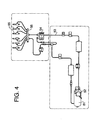
- an electromotive pressure feed pump 52 for dimethyl ether fuel supply is provided in a fuel tank 51, in such a manner that dimethyl ether is supplied to a high-pressure fuel pump 54 by the pressure feed pump 52, by means of a fuel pipe 53.
- the high-pressure fuel pump 54 is connected to a common fuel 56, to which a fuel injection device 55 is connected, and the dimethyl ether is supplied to the common rail 56 whilst being raised to a pressure suitable for injection into an engine.
- the high-pressure fuel pump 54 has a piston structure comprising a plunger, or the like, in such a manner that the pressure of the dimethyl ether is raised by reciprocal motion of this plunger.
- the lubrication of the plunger and plunger barrel inside the high-pressure fuel pump 54 is performed by the dimethyl ether fuel which contains an added lubricating agent.
- the present invention was devised in order to resolve the aforementioned problems, an object thereof being to provide a dimethyl ether fuel supply system capable of driving a high-pressure fuel pump, whilst ensuring internal lubrication of the high-pressure fuel pump.
- a first aspect of the present invention is a fuel supply system for a dimethyl ether engine, wherein dimethyl ether is supplied from a fuel tank to a high-pressure fuel pump whilst being raised to a saturated vapour pressure or above by means of a pressure feed pump and is then raised to a pressure suitable for injecting into an engine by means of the high-pressure fuel pump and supplied to a common rail to which fuel injection devices are connected, comprising: a dimethyl ether detecting device, disposed in a fuel pipe leading to the high-pressure fuel pump, for detecting the state of the dimethyl ether from the pressure feed pump; and an electronic control unit, connected to the dimethyl ether detecting device, for driving the high-pressure fuel pump when the dimethyl ether inside the fuel pipe leading to the high-pressure fuel pump is in a liquid state.
- the high-pressure fuel pump since the state of the dimethyl ether inside the fuel pipe leading to the high-pressure fuel pump is detected by a dimethyl ether detecting device, and the high-pressure fuel pump is driven by an electronic control unit in accordance with the state of the dimethyl ether, the high-pressure fuel pump is driven, causing compression of the dimethyl ether, only in cases where dimethyl ether in a liquid state is being supplied to the high-pressure fuel pump and hence lubrication thereof is ensured, thereby making it possible to prevent sticking, burning, or the like, of the internal mechanism of the high-pressure fuel pump.
- a second aspect of the present invention is a fuel supply system for a dimethyl ether engine according to the first aspect of the present invention, wherein the dimethyl ether detecting device consists of a temperature sensor for detecting the temperature of the dimethyl ether inside the fuel pipe leading to the aforementioned high-pressure fuel pump and a pressure sensor for detecting the pressure of the dimethyl ether.
- a third aspect of the present invention is the fuel supply system for a dimethyl ether engine according to either claim 1 or claim 2, wherein the electronic control unit is connected to an engine key section, as well as being connected to the pressure feed pump, and it activates the pressure feed pump when the engine key is set to an engine ON position, and activates the high-pressure fuel pump when the engine key is set to a starter ON position, only in cases where it is detected by the dimethyl ether detecting device that the dimethyl ether inside the fuel pipe leading to the high-pressure fuel pump is in a liquid state.
- a fourth aspect of the present invention is a fuel supply system for a dimethyl ether engine, wherein dimethyl ether is supplied from a fuel tank to a high-pressure fuel pump whilst being raised to a saturated vapour pressure or above by means of a pressure feed pump and is then raised to a pressure suitable for injecting into an engine by means of the high-pressure fuel pump and supplied to a common rail to which fuel injection devices are connected, comprising: an electronic control unit for activating the pressure feed pump when an engine key is set to an engine ON position, and activating the high-pressure fuel pump when the engine key is set to a starter ON position, after a prescribed period of time from the activation of the pressure feed pump.
- a fifth aspect of the present invention is the fuel supply system for a dimethyl ether engine according to the fourth aspect of the present invention, wherein the electronic control unit adjusts and changes the prescribed period of time in accordance with the internal temperature of the engine.
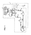
- Fig. 1 is an approximate compositional diagram of a preferred embodiment of a fuel supply system for a dimethyl ether engine relating to the present invention
- Fig. 2 is a graph of dimethyl ether vaporization pressure
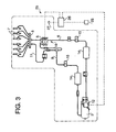
- Fig. 3 is an approximate compositional diagram of a further preferred embodiment of a fuel supply system for a dimethyl ether engine relating to the present invention.
- Fig. 4 is an approximate compositional diagram of a conventional fuel supply system for a dimethyl ether engine.
- Fig. 1 is an approximate compositional diagram of a preferred embodiment of a fuel supply system for a dimethyl ether engine relating to the present invention
- Fig. 2 is a graph of the dimethyl ether vaporization pressure.
- a fuel tank 3 is provided on the chassis side (not illustrated).
- a fuel pipe 6 is connected to the fuel tank 3 in order to supply dimethyl ether (DME) fuel to a high-pressure fuel pump 5 provided on the engine side (not illustrated).
- DME dimethyl ether
- a common rail 8 is connected to the high-pressure fuel pump 5, this common rail 8 being connected to a plurality of fuel injection devices (injectors) 7 for injecting fuel into the combustion chambers of the engine (not illustrated).
- a fuel return pipe 9 is connected to the high-pressure fuel pump 5 in order to return surplus fuel to the fuel tank 3.
- a fuel return pipe 11 is connected to an intermediate position of the fuel return pipe 9 in order to return the surplus fuel from the common rail 8 to the fuel 3.
- a pressure feed pump 12 is provided inside the fuel tank 3 in order to raise the pressure of the dimethyl ether to a saturated vapour pressure, or above, and supply it to the high-pressure fuel pump 5.
- 14 is a fuel cooler and 15 is a fuel cut-off valve.
- a characteristic feature of the present invention is that it comprises a dimethyl ether detecting device 16, provided at the inlet section 18 of the fuel pipe 6 to the high-pressure fuel pump 5, for sensing the state of the dimethyl ether supplied by the pressure feed pump 12, and an electronic control unit (ECU) 17, connected to the dimethyl ether detecting device 16, for driving the high-pressure fuel pump 5 when the dimethyl ether inside the fuel pipe 6 to the high-pressure fuel pump 5 is in a liquid state.
- ECU electronice control unit
- the dimethyl ether detecting device 16 is constituted by a temperature sensor 21 and a pressure sensor 22 which are provided in the fuel pipe 6 at the inlet section 18 of the high-pressure fuel pump 5.
- the temperature sensor 21 and pressure sensor 22 serve to measure the temperature and pressure of the dimethyl ether inside the fuel pipe 6.
- the relationship between temperature and vaporization pressure from the dimethyl ether vaporization pressure graph shown in Fig. 2 is input to the electronic control unit 17, in such a manner that the state of the dimethyl ether (namely, whether or not it is liquid) is detected from the temperature and pressure of the dimethyl ether at the inlet section 18 of the high-pressure fuel pump 5.
- the electronic control unit 17 is electrically connected to the high-pressure fuel pump 5 and the pressure feed pump 12, in such a manner that it sends drive signals to the high-pressure fuel pump 5 and pressure pump 12.
- the electronic control unit 17 is connected to an engine key section 23, and is set in such a manner that when the engine key is in the engine ON position, it activates the pressure feed pump 12, and when the engine key is in the starter ON position, it activates the high-pressure fuel pump 5 only in cases where the dimethyl ether detecting device 16 senses that the dimethyl ether at the inlet section 18 of the high-pressure fuel pump 5 is in a liquid state.
- the dimethyl ether detecting device 16 detects the temperature and pressure of the dimethyl ether at the inlet section 18 of the high-pressure fuel pump 5.
- the detected pressure and temperature are input to the electronic control unit 17 and compared with a dimethyl ether vaporization pressure graph previously input to the electronic control unit 17 (to detect whether the pressure at the inlet section 18 is higher or lower than the vaporization pressure at that temperature), and thereby it is sensed whether the dimethyl ether is in a liquid or gaseous state.
- the engine starter including the high-pressure fuel pump 5 is not started up, and the operations of driving the pressure feed pump 12 and sensing the state of the dimethyl ether are continued.
- the starter including the high-pressure fuel pump 5 is started.
- the dimethyl ether in a liquid state flows into the high-pressure fuel pump 5, the peripheral region of the plunger is lubricated thereby, and hence sticking, burning, and the like can be prevented.
- the high-pressure fuel pump 5 is only driven, thereby compressing the dimethyl ether, when dimethyl ether in a liquid state is supplied to the high-pressure fuel pump 5 and the lubrication thereof is ensured, and hence damage of the high-pressure fuel pump 5 can be prevented.
- the dimethyl ether detecting device 16 constantly detects the state of the dimethyl ether at the inlet section 18 of the high-pressure fuel pump 5, then in cases where the dimethyl ether supplied to the high-pressure fuel pump 5 is not in liquid form, not only at engine start up, but also due to a fault or other reason of some kind, then this is detected and the high-pressure fuel pump 5 can be halted, thereby preventing damage thereof.
- Fig. 3 is an approximate compositional diagram showing a further preferred embodiment of the fuel supply system for a dimethyl ether engine relating to the present invention.
- the fuel supply system 25 in Fig. 3 eliminates the dimethyl ether detecting device 16 of the fuel supply system 1 shown in Fig. 1, and the activation of the high-pressure fuel pump 5 is performed after a prescribed period of time has elapsed from the activation of the pressure feed pump 12.
- the electronic control unit 26 provided in the fuel supply system 25 comprises a timer function, and the pressure feed pump 12 is activated when the engine key is in the engine ON position, and the high-pressure fuel pump 5 is activated when the engine key is in the starter ON position, after a previously determined prescribed period of time has elapsed from the activation of the pressure feed pump 12.
- a temperature sensor 27 for detecting the internal temperature of the engine chamber is connected to the electronic control unit 26, in such a manner that the aforementioned period of time is adjusted according to the internal temperature of the engine chamber as detected by the temperature sensor.
- composition is the same that the fuel supply system 1 in Fig. 1 and is similarly labelled, further description thereof being omitted here.
- the high-pressure fuel pump is driven to cause compression of the dimethyl ether, only in states where the internal lubrication of the high-pressure fuel pump is ensured, an excellent advantage is obtained in that damaging of the high-pressure fuel pump can be prevented.
Landscapes
- Engineering & Computer Science (AREA)
- Chemical & Material Sciences (AREA)
- Combustion & Propulsion (AREA)
- Mechanical Engineering (AREA)
- General Engineering & Computer Science (AREA)
- Fuel-Injection Apparatus (AREA)
- Electrical Control Of Air Or Fuel Supplied To Internal-Combustion Engine (AREA)
- Output Control And Ontrol Of Special Type Engine (AREA)
Claims (5)
- Système d'alimentation en carburant destiné à un moteur fonctionnant au diméthyle éther, dans lequel le diméthyle éther est délivré depuis un réservoir de carburant (3) à une pompe à carburant haute pression (5) tout en étant élevé à une pression de vapeur saturée ou plus à l'aide d'une pompe d'alimentation sous pression (12) puis à une pression appropriée pour être injecté dans un moteur à l'aide de la pompe à carburant haute pression (5), et est délivré à une rampe commune (8) à laquelle sont raccordés les dispositifs d'injection de carburant (7), caractérisé par :un dispositif de détection du diméthyle éther (16), disposé dans un tuyau d'alimentation en carburant (6) menant à ladite pompe à carburant haute pression (5), pour détecter l'état du diméthyle éther depuis la pompe d'alimentation sous pression (12) ; etune unité de commande électronique (17), raccordée audit dispositif de détection du diméthyle éther (16), permettant d'entraíner ladite pompe à carburant haute pression (5) lorsque le diméthyle éther se trouvant à l'intérieur du tuyau d'alimentation en carburant (6) menant à la pompe à carburant haute pression (5) est dans un état liquide.
- Système d'alimentation en carburant destiné à un moteur fonctionnant au diméthyle éther selon la revendication 1, dans lequel ledit dispositif de détection du diméthyle éther comprend une sonde de température permettant de détecter la température du diméthyle éther à l'intérieur du tuyau d'alimentation en carburant menant à ladite pompe à carburant haute pression, ainsi qu'une sonde de pression permettant de détecter la pression dudit diméthyle éther.
- Système d'alimentation en carburant destiné à un moteur fonctionnant au diméthyle éther selon la revendication 1 ou 2, dans lequel ladite unité de commande électronique est raccordée à une section de clef de démarrage du moteur, tout en étant raccordée à ladite pompe d'alimentation sous pression, et elle actionne ladite pompe d'alimentation sous pression lorsque la clef de démarrage du moteur est fixée sur une position de MARCHE du moteur, et actionne ladite pompe à carburant haute pression lorsque la clef de démarrage du moteur est fixée sur une position de MARCHE en phase de démarrage, seulement dans les cas où il est détecté, par ledit dispositif de détection du diméthyle éther, que le diméthyle éther se trouvant à l'intérieur du tuyau d'alimentation en carburant menant à ladite pompe à carburant haute pression est dans un état liquide.
- Système d'alimentation en carburant destiné à un moteur fonctionnant au diméthyle éther, dans lequel le diméthyle éther est délivré depuis un réservoir de carburant (3) à une pompe à carburant haute pression (5) tout en étant élevé à une pression de vapeur saturée ou plus à l'aide d'une pompe d'alimentation sous pression (12), puis à une pression appropriée pour être injecté dans un moteur à l'aide de la pompe à carburant haute pression (5), et est délivré à une rampe commune (8) à laquelle sont raccordés les dispositifs d'injection du carburant (7), caractérisé par une unité de commande électronique permettant d'actionner ladite pompe d'alimentation sous pression (12) lorsqu'une clef de démarrage du moteur est fixée sur une position de MARCHE du moteur, et actionner ladite pompe à carburant haute pression (5) lorsque la clef de démarrage du moteur est fixée sur une position de MARCHE en phase de démarrage, après un laps de temps prescrit à compter de l'actionnement de ladite pompe d'alimentation sous pression (12).
- Système d'alimentation en carburant destiné à un moteur fonctionnant au diméthyle éther selon la revendication 4, dans lequel ladite unité de commande électronique règle et modifie ledit laps de temps prescrit en fonction de la température interne du moteur.
Applications Claiming Priority (2)
| Application Number | Priority Date | Filing Date | Title |
|---|---|---|---|
| JP2001082894 | 2001-03-22 | ||
| JP2001082894A JP2002276473A (ja) | 2001-03-22 | 2001-03-22 | ジメチルエーテルエンジンの燃料供給システム |
Publications (2)
| Publication Number | Publication Date |
|---|---|
| EP1243786A1 EP1243786A1 (fr) | 2002-09-25 |
| EP1243786B1 true EP1243786B1 (fr) | 2003-12-17 |
Family
ID=18938778
Family Applications (1)
| Application Number | Title | Priority Date | Filing Date |
|---|---|---|---|
| EP02006209A Expired - Lifetime EP1243786B1 (fr) | 2001-03-22 | 2002-03-19 | Système d'alimentation en carburant d'un moteur à combustion interne fonctionnant au diméthyle éther |
Country Status (4)
| Country | Link |
|---|---|
| US (1) | US6742479B2 (fr) |
| EP (1) | EP1243786B1 (fr) |
| JP (1) | JP2002276473A (fr) |
| DE (1) | DE60200131T2 (fr) |
Families Citing this family (28)
| Publication number | Priority date | Publication date | Assignee | Title |
|---|---|---|---|---|
| CN100400846C (zh) * | 2002-03-06 | 2008-07-09 | 株式会社博世汽车系统 | 柴油机的dme燃油供给装置 |
| DE102007052959B4 (de) * | 2007-03-15 | 2018-11-08 | Korea Institute Of Energy Research | Tragbare Stromerzeugungsvorrichtung, Vorrichtung zur Versorgung mit Kraftstoff und Luft für die tragbare Stromerzeugungsvorrichtung, Mikromotor mit Gleichstromspülung für die tragbare Stromerzeugungsvorrichtung |
| JP4787208B2 (ja) * | 2007-05-18 | 2011-10-05 | ボッシュ株式会社 | 液化ガス燃料供給装置及び液化ガス燃料供給装置の高圧ポンプの駆動方法 |
| US7523747B2 (en) * | 2007-09-21 | 2009-04-28 | Ultimate Combustion Corporation | Method and system for liquid fuel conditioning |
| WO2009082280A1 (fr) | 2007-12-20 | 2009-07-02 | Volvo Technology Corporation | Système de pompage de carburant, procédé de fonctionnement d'un système de pompage de carburant et système d'injection de carburant comportant un système de pompage de carburant |
| CN101509417B (zh) * | 2009-03-20 | 2011-05-25 | 天津大学 | 二甲醚共轨式电控喷射系统 |
| JP5501682B2 (ja) * | 2009-07-16 | 2014-05-28 | ヤンマー株式会社 | Dme燃料供給システム及びdme燃料の冷却方法 |
| JP5259514B2 (ja) * | 2009-07-16 | 2013-08-07 | ヤンマー株式会社 | Dmeエンジンの起動方法 |
| DE102009043718B4 (de) * | 2009-10-01 | 2015-08-20 | Avl List Gmbh | System und Verfahren zur Messung von Einspritzvorgängen in einer Verbrennungskraftmaschine |
| US20110226219A1 (en) * | 2010-03-17 | 2011-09-22 | Caterpillar Inc. | Fuel lubricated pump and common rail fuel system using same |
| US8590510B2 (en) | 2010-08-24 | 2013-11-26 | Ford Global Technologies, Llc | Fuel system for a multi-fuel engine |
| CN103850838A (zh) * | 2010-09-13 | 2014-06-11 | 株式会社电装 | 燃料供给设备 |
| US8776764B2 (en) | 2011-01-04 | 2014-07-15 | Ford Global Technologies, Llc | Fuel system for a multi-fuel engine |
| RU2587030C2 (ru) * | 2011-06-14 | 2016-06-10 | Вольво Ластвагнар Аб | Топливная система и способ снижения утечки топлива из топливной системы |
| US9217405B2 (en) | 2011-06-22 | 2015-12-22 | Ford Global Technologies, Llc | System and method for lubricating a fuel pump |
| KR101294544B1 (ko) * | 2011-08-01 | 2013-08-07 | 현대자동차주식회사 | 디메틸에테르 연료 차량의 연료 냉각 시스템 |
| US9303605B2 (en) * | 2011-11-10 | 2016-04-05 | GM Global Technology Operations LLC | System and method for circulating fuel through a direct injection pump of a bi-fuel engine |
| KR101294395B1 (ko) * | 2011-11-15 | 2013-08-08 | 현대자동차주식회사 | 디메틸에테르 커먼 레일 연료 공급 장치 및 그 방법 |
| WO2013102467A1 (fr) * | 2012-01-03 | 2013-07-11 | Volvo Lastvagnar Ab | Système de carburant et procédé correspondant |
| KR101361347B1 (ko) * | 2012-12-28 | 2014-02-10 | 현대자동차주식회사 | 디메틸에테르 연료용 커먼레일 시스템 |
| US9587578B2 (en) | 2013-12-06 | 2017-03-07 | Ford Global Technologies, Llc | Adaptive learning of duty cycle for a high pressure fuel pump |
| US9243598B2 (en) | 2014-02-25 | 2016-01-26 | Ford Global Technologies, Llc | Methods for determining fuel bulk modulus in a high-pressure pump |
| US9458806B2 (en) | 2014-02-25 | 2016-10-04 | Ford Global Technologies, Llc | Methods for correcting spill valve timing error of a high pressure pump |
| US9874185B2 (en) | 2014-05-21 | 2018-01-23 | Ford Global Technologies, Llc | Direct injection pump control for low fuel pumping volumes |
| US9638153B2 (en) * | 2015-02-20 | 2017-05-02 | Ford Global Technologies, Llc | Method for cooling a direct injection pump |
| CN112901380B (zh) * | 2020-09-01 | 2022-06-21 | 太原理工大学 | 一种压燃式甲醇发动机燃料供给系统及其控制方法 |
| DE102021119723A1 (de) | 2021-07-29 | 2023-02-02 | Liebherr-Components Deggendorf Gmbh | Verfahren zum Betreiben einer Brennkraftmaschine mit einem Gemisch aus Ammoniak und Dimethylether und Brennkraftmaschine hierfür |
| WO2023090386A1 (fr) | 2021-11-22 | 2023-05-25 | Hitachi Astemo, Ltd. | Système d'alimentation en carburant et procédé de commande d'une pompe à carburant d'un système d'alimentation en carburant pour un moteur à combustion interne |
Family Cites Families (17)
| Publication number | Priority date | Publication date | Assignee | Title |
|---|---|---|---|---|
| EP0020012A1 (fr) * | 1979-05-14 | 1980-12-10 | Aeci Ltd | Combustible et procédé de fonctionnement d'un moteur |
| JPS57153952A (en) * | 1981-03-19 | 1982-09-22 | Nissan Motor Co Ltd | Starting device of alcohol engine |
| US4444158A (en) * | 1982-09-03 | 1984-04-24 | Conoco Inc. | Alcohol dissociation process for automobiles |
| JPH068630B2 (ja) | 1985-05-30 | 1994-02-02 | 日本特殊陶業株式会社 | グロ−プラグの通電制御装置 |
| JPH0388957A (ja) * | 1989-08-22 | 1991-04-15 | New Zealand Government | 圧縮点火エンジンの燃料供給装置及びその制御装置 |
| US5632786A (en) * | 1995-09-14 | 1997-05-27 | Amoco Corporation | Process and fuel for spark ignition engines |
| JP3742996B2 (ja) | 1996-03-25 | 2006-02-08 | 株式会社デンソー | 燃料供給装置 |
| GB2316981A (en) * | 1996-09-10 | 1998-03-11 | Lucas Ind Plc | Fuel pump for engine |
| JPH1089185A (ja) | 1996-09-11 | 1998-04-07 | Zexel Corp | ガソリン機関の燃料噴射装置 |
| AT1924U3 (de) | 1997-06-26 | 1998-09-25 | Avl List Gmbh | Einspritzsystem für eine mit flüssiggas betriebene brennkraftmaschine mit innerer verbrennung |
| JP3456689B2 (ja) | 1997-09-30 | 2003-10-14 | 日野自動車株式会社 | ジメチルエーテル燃料使用ディーゼルエンジン燃料システム |
| JPH11125161A (ja) * | 1997-10-23 | 1999-05-11 | Denso Corp | 内燃機関の燃料供給装置 |
| JPH11210557A (ja) * | 1998-01-30 | 1999-08-03 | Aisan Ind Co Ltd | エンジンの液化ガス燃料供給装置 |
| DE19818421B4 (de) * | 1998-04-24 | 2017-04-06 | Robert Bosch Gmbh | Kraftstoffversorgungsanlage einer Brennkraftmaschine |
| FR2779775B1 (fr) * | 1998-06-10 | 2000-07-13 | Renault | Dispositif et procede d'alimentation en carburant d'un moteur a combustion interne |
| JP2000110687A (ja) | 1998-10-05 | 2000-04-18 | Nkk Corp | ディーゼル機関用低沸点燃料供給装置 |
| US6076487A (en) * | 1999-02-25 | 2000-06-20 | Go-Tec | Internal combustion system using acetylene fuel |
-
2001
- 2001-03-22 JP JP2001082894A patent/JP2002276473A/ja active Pending
-
2002
- 2002-03-19 EP EP02006209A patent/EP1243786B1/fr not_active Expired - Lifetime
- 2002-03-19 DE DE60200131T patent/DE60200131T2/de not_active Expired - Lifetime
- 2002-03-21 US US10/103,578 patent/US6742479B2/en not_active Expired - Lifetime
Also Published As
| Publication number | Publication date |
|---|---|
| DE60200131T2 (de) | 2004-09-02 |
| EP1243786A1 (fr) | 2002-09-25 |
| US6742479B2 (en) | 2004-06-01 |
| JP2002276473A (ja) | 2002-09-25 |
| DE60200131D1 (de) | 2004-01-29 |
| US20020134323A1 (en) | 2002-09-26 |
Similar Documents
| Publication | Publication Date | Title |
|---|---|---|
| US6742479B2 (en) | Fuel supply system for dimethyl ether engine | |
| US6024064A (en) | High pressure fuel injection system for internal combustion engine | |
| EP0979940B1 (fr) | Procédé et dispositif de commande de l'injection de carburant dans un moteur à combustion interne | |
| US7267108B2 (en) | Fuel system pressure relief valve with integral accumulator | |
| US7717077B2 (en) | Internal combustion engine starting system and method | |
| JPH07167009A (ja) | エンジンへの燃料供給装置 | |
| US6076507A (en) | Pump system for preventing hot start knock in a diesel engine | |
| JP4045594B2 (ja) | 蓄圧式燃料噴射装置 | |
| RU2177078C2 (ru) | Способ нагнетания давления в системе впрыска топлива, относящейся по типу к системам газового впрыска | |
| JP3780933B2 (ja) | 内燃機関の高圧燃料供給装置 | |
| JP3546285B2 (ja) | 蓄圧式エンジンの燃料噴射制御装置 | |
| US6047682A (en) | Accumulating type fuel injection control | |
| JP2009079514A (ja) | 筒内噴射式内燃機関の燃圧制御装置 | |
| EP1789668B1 (fr) | Systeme de commande permettant de commander un injecteur bi-carburant par systeme de carburant cylindrique pendant le demarrage moteur | |
| KR20030020442A (ko) | 내연기관의 작동 및 내연기관용 연료 시스템의 작동을위한 방법, 컴퓨터 프로그램 및 제어 및/또는 조절장치 | |
| JP6172198B2 (ja) | エンジンの制御装置 | |
| JP4035825B2 (ja) | 内燃機関用燃料噴射装置 | |
| JPH07238857A (ja) | 燃料噴射装置 | |
| US6105561A (en) | Fuel feeding system and method for an internal combustion engine able to be operated selectively with gasoline or gas | |
| JP3716498B2 (ja) | 直接噴射式内燃機関の燃料供給装置 | |
| JP2001501271A (ja) | 自動車における内燃機関の作動のための方法 | |
| KR101819897B1 (ko) | 직접분사식 엘피아이 시스템 | |
| JP3276211B2 (ja) | 燃料・水噴射装置 | |
| JPH10122022A (ja) | 燃料噴射装置 | |
| KR0139755Y1 (ko) | 자동차 리턴연료 공급장치 |
Legal Events
| Date | Code | Title | Description |
|---|---|---|---|
| PUAI | Public reference made under article 153(3) epc to a published international application that has entered the european phase |
Free format text: ORIGINAL CODE: 0009012 |
|
| AK | Designated contracting states |
Kind code of ref document: A1 Designated state(s): AT BE CH CY DE DK ES FI FR GB GR IE IT LI LU MC NL PT SE TR |
|
| AX | Request for extension of the european patent |
Free format text: AL;LT;LV;MK;RO;SI |
|
| GRAH | Despatch of communication of intention to grant a patent |
Free format text: ORIGINAL CODE: EPIDOS IGRA |
|
| 17P | Request for examination filed |
Effective date: 20030214 |
|
| AKX | Designation fees paid |
Designated state(s): DE FR GB IT SE |
|
| GRAS | Grant fee paid |
Free format text: ORIGINAL CODE: EPIDOSNIGR3 |
|
| RTI1 | Title (correction) |
Free format text: FUEL SUPPLY SYSTEM FOR DIMETHYL ETHER ENGINE |
|
| GRAA | (expected) grant |
Free format text: ORIGINAL CODE: 0009210 |
|
| AK | Designated contracting states |
Kind code of ref document: B1 Designated state(s): DE FR GB IT SE |
|
| REG | Reference to a national code |
Ref country code: GB Ref legal event code: FG4D |
|
| REF | Corresponds to: |
Ref document number: 60200131 Country of ref document: DE Date of ref document: 20040129 Kind code of ref document: P |
|
| REG | Reference to a national code |
Ref country code: SE Ref legal event code: TRGR |
|
| ET | Fr: translation filed | ||
| PLBE | No opposition filed within time limit |
Free format text: ORIGINAL CODE: 0009261 |
|
| STAA | Information on the status of an ep patent application or granted ep patent |
Free format text: STATUS: NO OPPOSITION FILED WITHIN TIME LIMIT |
|
| 26N | No opposition filed |
Effective date: 20040920 |
|
| PGFP | Annual fee paid to national office [announced via postgrant information from national office to epo] |
Ref country code: IT Payment date: 20090317 Year of fee payment: 8 Ref country code: SE Payment date: 20090306 Year of fee payment: 8 |
|
| EUG | Se: european patent has lapsed | ||
| PG25 | Lapsed in a contracting state [announced via postgrant information from national office to epo] |
Ref country code: IT Free format text: LAPSE BECAUSE OF NON-PAYMENT OF DUE FEES Effective date: 20100319 |
|
| PG25 | Lapsed in a contracting state [announced via postgrant information from national office to epo] |
Ref country code: SE Free format text: LAPSE BECAUSE OF NON-PAYMENT OF DUE FEES Effective date: 20100320 |
|
| PGFP | Annual fee paid to national office [announced via postgrant information from national office to epo] |
Ref country code: FR Payment date: 20130325 Year of fee payment: 12 |
|
| REG | Reference to a national code |
Ref country code: FR Ref legal event code: ST Effective date: 20141128 |
|
| PG25 | Lapsed in a contracting state [announced via postgrant information from national office to epo] |
Ref country code: FR Free format text: LAPSE BECAUSE OF NON-PAYMENT OF DUE FEES Effective date: 20140331 |
|
| REG | Reference to a national code |
Ref country code: DE Ref legal event code: R082 Ref document number: 60200131 Country of ref document: DE Representative=s name: SCHAUMBURG & PARTNER PATENTANWAELTE GBR, DE Ref country code: DE Ref legal event code: R082 Ref document number: 60200131 Country of ref document: DE Representative=s name: SCHAUMBURG UND PARTNER PATENTANWAELTE MBB, DE |
|
| PGFP | Annual fee paid to national office [announced via postgrant information from national office to epo] |
Ref country code: DE Payment date: 20160315 Year of fee payment: 15 |
|
| PGFP | Annual fee paid to national office [announced via postgrant information from national office to epo] |
Ref country code: GB Payment date: 20160316 Year of fee payment: 15 |
|
| REG | Reference to a national code |
Ref country code: DE Ref legal event code: R119 Ref document number: 60200131 Country of ref document: DE |
|
| GBPC | Gb: european patent ceased through non-payment of renewal fee |
Effective date: 20170319 |
|
| PG25 | Lapsed in a contracting state [announced via postgrant information from national office to epo] |
Ref country code: DE Free format text: LAPSE BECAUSE OF NON-PAYMENT OF DUE FEES Effective date: 20171003 |
|
| PG25 | Lapsed in a contracting state [announced via postgrant information from national office to epo] |
Ref country code: GB Free format text: LAPSE BECAUSE OF NON-PAYMENT OF DUE FEES Effective date: 20170319 |